Page 49 of 86

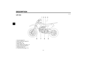
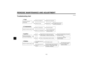
PERIODIC MAINTENANCE AND ADJUSTMENT
7-8
7
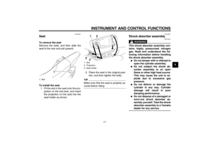
To install the panel
1. Place the panel in the original posi-
tion, and then install the bolt.
2. Install the seat.
EAU19604
Checking the spark plug The spark plug is an important engine
component, which is easy to check.
Since heat and deposits will cause any
spark plug to slowly erode, the spark
plug should be removed and checked
in accordance with the periodic mainte-
nance and lubrication chart. In addition,
the condition of the spark plug can re-
veal the condition of the engine.
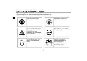
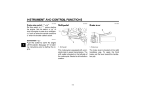
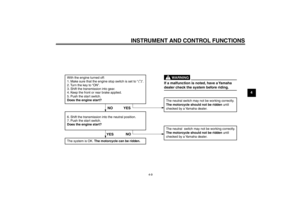
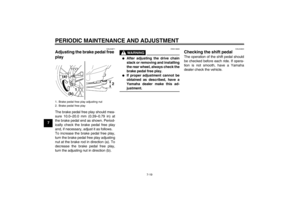
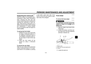
To remove the spark plug 1. Remove the spark plug cap.
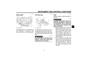
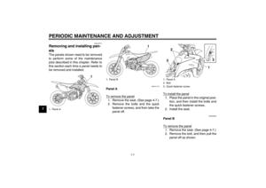
2. Remove the spark plug as shown, with the spark plug wrench includ-
ed in the owner ’s tool kit. To check the spark plug
1. Check that the porcelain insulator around the center electrode of the
spark plug is a medium-to-light tan
(the ideal color when the vehicle is
ridden normally).
TIPIf the spark plug shows a distinctly dif-
ferent color, the engine could be oper-
ating improperly. Do not attempt to
diagnose such problems yourself. In-
stead, have a Yamaha dealer check
the vehicle.
1. Panel B
2. Bolt
3. Projection
3
1
2
1. Spark plug cap
1
1. Spark plug wrench
1
U5B684E0.book Page 8 Monday, June 13, 2011 4:46 PM
Page 50 of 86

PERIODIC MAINTENANCE AND ADJUSTMENT
7-9
72. Check the spark plug for electrode
erosion and excessive carbon or
other deposits, and replace it if
necessary.
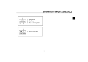
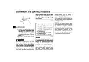
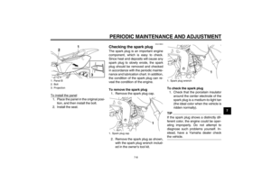
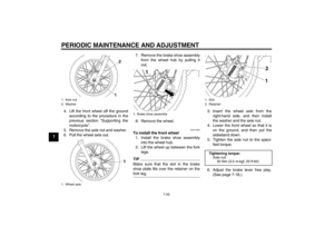
3. Measure the spark plug gap with a wire thickness gauge and, if nec-
essary, adjust the gap to specifica-
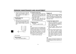
tion. To install the spark plug
1. Clean the surface of the spark plug gasket and its mating surface, and
then wipe off any grime from the
spark plug threads.
2. Install the spark plug with the spark plug wrench, and then tight-
en it to the specified torque.
TIPIf a torque wrench is not available when
installing a spark plug, a good estimate
of the correct torque is 1/4 –1/2 turn
past finger tight. However, the spark
plug should be tightened to the speci-
fied torque as soon as possible.3. Install the spark plug cap.
EAU39845
Engine oil The engine oil level should be checked
before each ride. In addition, the oil
must be changed at the intervals spec-
ified in the periodic maintenance and
lubrication chart.
To check the engine oil level 1. Place the motorcycle on a level surface and hold it in an upright po-
sition. A slight tilt to the side can re-
sult in a false reading.
2. Start the engine, warm it up for several minutes, and then turn it
off.
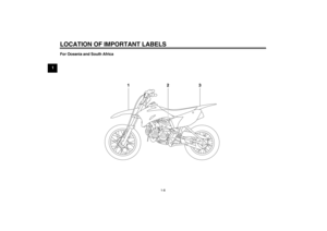
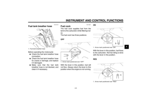
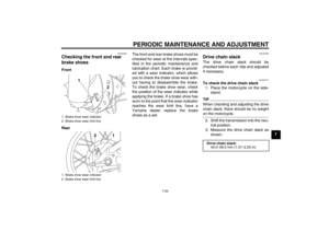
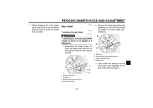
3. Wait a few minutes until the oil set- tles, remove the engine oil filler
cap, wipe the engine oil dipstick
clean, insert it back into the oil filler
hole (without screwing it in), and
then remove it again to check the
oil level.TIPThe engine oil should be between the
tip of the dipstick and the maximum lev-
el mark.
Specified spark plug:NGK/CR6HSA1. Spark plug gapSpark plug gap:0.6 –0.7 mm (0.024 –0.028 in)
Tightening torque:
Spark plug:13 Nm (1.3 m ·kgf, 9.4 ft· lbf)
U5B684E0.book Page 9 Monday, June 13, 2011 4:46 PM
Page 51 of 86

PERIODIC MAINTENANCE AND ADJUSTMENT
7-10
7
4. If the engine oil is not between the
tip of the dipstick and the maxi-
mum level mark, add sufficient oil
of the recommended type to raise
it to the correct level.
5. Insert the dipstick into the oil filler hole, and then tighten the oil filler
cap.
To change the engine oil 1. Start the engine, warm it up for several minutes, and then turn it
off.
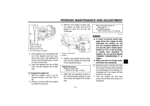
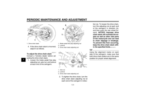
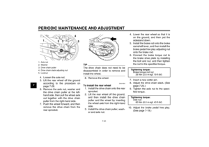
2. Place an oil pan under the engine to collect the used oil. 3. Remove the engine oil filler cap,
the engine oil drain bolt and its
gasket to drain the oil from the
crankcase.
4. Install a new gasket and the drain bolt, and then tighten the drain bolt
to the specified torque.
5. Refill with the specified amount of the recommended engine oil, and
then install and tighten the oil filler
cap.
NOTICE
ECA11620
�
In order to prevent clutch slip-
page (since the engine oil also
lubricates the clutch), do not
mix any chemical additives. Do
not use oils with a diesel speci-
fication of “CD” or oils of a high-
er quality than specified. In
addition, do not use oils labeled
“ ENERGY CONSERVING II ” or
higher.
�
Make sure that no foreign mate-
rial enters the crankcase.
6. Start the engine, and then let it idle for several minutes while checking
it for oil leakage. If oil is leaking, im-
mediately turn the engine off and
check for the cause.
7. Turn the engine off, and then check the oil level and correct it if
necessary.
1. Engine oil filler cap
2. Engine oil dipstick
3. Maximum level mark
4. Tip of the engine oil dipstick
1
3
4
2
1. Engine oil drain bolt
2. Gasket
Tightening torque: Engine oil drain bolt:20 Nm (2.0 m ·kgf, 14 ft ·lbf)
1
1
2
Recommended engine oil:See page 9-1.
Oil change quantity: 0.80 L (0.85 US qt, 0.70 Imp.qt)
U5B684E0.book Page 10 Monday, June 13, 2011 4:46 PM
Page 52 of 86

PERIODIC MAINTENANCE AND ADJUSTMENT
7-11
7
EAU41636
Cleaning the air filter element The air filter element should be cleaned
or replaced at the intervals specified in
the periodic maintenance and lubrica-
tion chart. Clean or, if necessary, re-
place the air filter element more
frequently if you are riding in unusually
wet or dusty areas.
To clean the air filter element1. Remove panel A. (See page 7-7.)
2. Remove the air filter case cover by removing the screws.
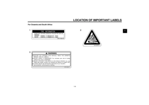
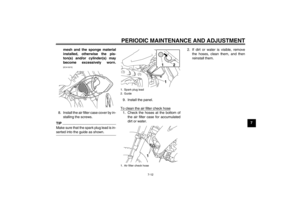
3. Pull the sponge material and the mesh out. 4. Clean the mesh with solvent, and
then wipe the solvent off.
5. Clean the sponge material with solvent, and then squeeze the re-
maining solvent out. WARNING!
Use only a dedicated parts
cleaning solvent. To avoid the
risk of fire or explosion, do not
use gasoline or solvents with a
low flash point.
[EWA10431]
NOTICE:
To avoid damaging the foam
material, handle it gently and
carefully, and do not twist or
wring it.
[ECA10511]
6. Apply oil of the recommended type to the entire surface of the sponge
material, and then squeeze the ex-
cess oil out.TIPThe sponge material should be wet but
not dripping.7. Insert the mesh and the spongematerial into the air filter case.
NOTICE: Make sure that the
mesh and the sponge material
are properly seated in the air fil-
ter case. The engine should
never be operated without the
1. Air filter case cover
2. Screw
2
1
1. Sponge material
2. Air filter mesh
1
2
Recommended oil:
Yamaha foam air filter oil or other
quality foam air filter oil
U5B684E0.book Page 11 Monday, June 13, 2011 4:46 PM
Page 53 of 86
PERIODIC MAINTENANCE AND ADJUSTMENT
7-12
7
mesh and the sponge material
installed, otherwise the pis-
ton(s) and/or cylinder(s) may
become excessively worn.
[ECA15572]
8. Install the air filter case cover by in-
stalling the screws.TIPMake sure that the spark plug lead is in-
serted into the guide as shown.
9. Install the panel.
To clean the air filter check hose1. Check the hoses at the bottom of the air filter case for accumulated
dirt or water. 2. If dirt or water is visible, remove
the hoses, clean them, and then
reinstall them.1. Spark plug lead
2. Guide
1. Air filter check hose
11
2
1
U5B684E0.book Page 12 Monday, June 13, 2011 4:46 PM
Page 54 of 86

PERIODIC MAINTENANCE AND ADJUSTMENT
7-13
7
EAU40421
Cleaning the spark arrester The spark arrester should be cleaned
at the intervals specified in the periodic
maintenance and lubrication chart.
WARNING
EWA10980
�
Always let the exhaust system
cool prior to touching exhaust
components.
�
Do not start the engine when
cleaning the exhaust system.
TIPMake sure to select a well-ventilated
area free of combustible materials to
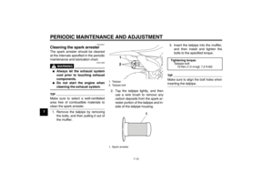
clean the spark arrester.1. Remove the tailpipe by removingthe bolts, and then pulling it out of
the muffler. 2. Tap the tailpipe lightly, and then
use a wire brush to remove any
carbon deposits from the spark ar-
rester portion of the tailpipe and in-
side of the tailpipe housing. 3. Insert the tailpipe into the muffler,
and then install and tighten the
bolts to the specified torque.
TIPMake sure to align the bolt holes when
inserting the tailpipe.
1. Tailpipe
2. Tailpipe bolt
1. Spark arrester
21
1
Tightening torque:
Tailpipe bolt:10 Nm (1.0 m ·kgf, 7.2 ft· lbf)
U5B684E0.book Page 13 Monday, June 13, 2011 4:46 PM
Page 55 of 86

PERIODIC MAINTENANCE AND ADJUSTMENT
7-14
7
EAU39930
Adjusting the carburetor The carburetor is an important part of
the engine and requires very sophisti-
cated adjustment. Therefore, most car-
buretor adjustments should be left to a
Yamaha dealer, who has the neces- sary professional knowledge and expe-
rience. The adjustment described in the
following section, however, may be ser-
viced by the owner as part of routine
maintenance.NOTICE
ECA10550
The carburetor has been set and ex-
tensively tested at the Yamaha fac-
tory. Changing these settings
without sufficient technical knowl-
edge may result in poor perfor-
mance of or damage to the engine.
EAU21362
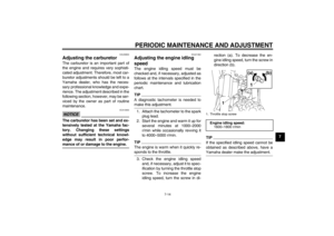
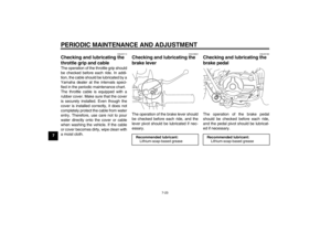
Adjusting the engine idling
speed The engine idling speed must be
checked and, if necessary, adjusted as
follows at the intervals specified in the
periodic maintenance and lubrication
chart.TIPA diagnostic tachometer is needed to
make this adjustment.1. Attach the tachometer to the spark plug lead.
2. Start the engine and warm it up for several minutes at 1000 –2000
r/min while occasionally revving it
to 4000 –5000 r/min.TIPThe engine is warm when it quickly re-
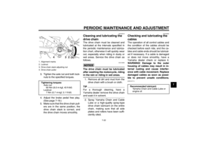
sponds to the throttle.3. Check the engine idling speed
and, if necessary, adjust it to spec-
ification by turning the throttle stop
screw. To increase the engine
idling speed, turn the screw in di- rection (a). To decrease the en-
gine idling speed, turn the screw in
direction (b).
TIPIf the specified idling speed cannot be
obtained as described above, have a
Yamaha dealer make the adjustment.1. Throttle stop screw
Engine idling speed:
1600– 1800 r/min
1 (a) (b)
1
U5B684E0.book Page 14 Monday, June 13, 2011 4:46 PM
Page 56 of 86
 at the
inner edge of the throttle")
PERIODIC MAINTENANCE AND ADJUSTMENT
7-15
7
EAU21384
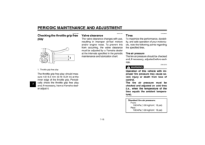
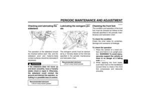
Checking the throttle grip free
play The throttle grip free play should mea-
sure 4.0–6.0 mm (0.16 –0.24 in) at the
inner edge of the throttle grip. Periodi-
cally check the throttle grip free play
and, if necessary, have a Yamaha deal-
er adjust it.
EAU21401
Valve clearance The valve clearance changes with use,
resulting in improper air-fuel mixture
and/or engine noise. To prevent this
from occurring, the valve clearance
must be adjusted by a Yamaha dealer
at the intervals specified in the periodic
maintenance and lubrication chart.
EAU39824
Tires To maximize the performance, durabil-
ity, and safe operation of your motorcy-
cle, note the following points regarding
the specified tires.
Tire air pressure
The tire air pressure should be checked
and, if necessary, adjusted before each
ride.
WARNING
EWA15370
Operation of this vehicle with im-
proper tire pressure may cause se-
vere injury or death from loss of
control.
The tire air pressure must be
checked and adjusted on cold tires
(i.e., when the temperature of the
tires equals the ambient tempera-
ture).
1. Throttle grip free play
1
Standard tire air pressure: Fr o nt :100 kPa (1.00 kgf/cm ², 15 psi)
Rear:
100 kPa (1.00 kgf/cm ², 15 psi)
U5B684E0.book Page 15 Monday, June 13, 2011 4:46 PM


![YAMAHA TTR110 2012 Owners Manual PERIODIC MAINTENANCE AND ADJUSTMENT
7-12
7
mesh and the sponge material
installed, otherwise the pis-
ton(s) and/or cylinder(s) may
become excessively worn.
[ECA15572]
8. Install the air filter case c](/manual-img/51/51631/w960_51631-52.png "YAMAHA TTR110 2012 Owners Manual PERIODIC MAINTENANCE AND ADJUSTMENT
7-12
7
mesh and the sponge material
installed, otherwise the pis-
ton(s) and/or cylinder(s) may
become excessively worn.
[ECA15572]
8. Install the air filter case c")