Page 33 of 104
 stops the
engine when the switch is pushed.
EJU31163Engine shut-off switch“”
The engine shut-of")
Control function operation
27
EJU31152Engine stop switch“”
The engine stop switch (red button) stops the
engine when the switch is pushed.
EJU31163Engine shut-off switch“”
The engine shut-off switch automatically
stops the engine when the clip, on the end of
the engine shut-off cord (lanyard), is removed
from the switch, such as if the operator falls off
the watercraft.
Insert the clip under the engine shut-off switch
before starting the engine.
When the engine is not running, remove the
clip from the engine shut-off switch to preventaccidental starting or unauthorized operation
by children or others.
EJU36286Start switch“”
NOTICE
ECJ01310
Do not run the engine over 4000 r/min on
land. Also, do not run the engine for more
than 15 seconds without supplying water,
otherwise the engine could overheat.
The start switch (green button) starts the en-
gine when the switch is pushed.
Release the start switch as soon as the en-
gine starts to run. If the engine does not start
in 5 seconds, release the start switch, wait 15
seconds, and then try again. NOTICE: Never
push the start switch while the engine is
running. Do not operate the start switch
for more than 5 seconds, otherwise the
battery will be discharged and the engine
1Engine stop switch
1Engine shut-off switch
2Clip
3Engine shut-off cord (lanyard)
1
2
1
3
UF2R73E0.book Page 27 Monday, June 20, 2011 9:44 AM
Page 34 of 104
![YAMAHA FZR 2012 Owners Manual Control function operation
28
will not start. Also, the starter motor could
be damaged.
[ECJ01040]
The engine will not start under any of the fol-
lowing conditions:
�Lock mode of the Yamaha Security](/manual-img/51/50149/w960_50149-33.png "YAMAHA FZR 2012 Owners Manual Control function operation
28
will not start. Also, the starter motor could
be damaged.
[ECJ01040]
The engine will not start under any of the fol-
lowing conditions:
�Lock mode of the Yamaha Security")
Control function operation
28
will not start. Also, the starter motor could
be damaged.
[ECJ01040]
The engine will not start under any of the fol-
lowing conditions:
�Lock mode of the Yamaha Security System
has been selected. (See page 26 for
Yamaha Security System setting proce-
dures.)
�Clip is removed from the engine shut-off
switch.
�Throttle lever is squeezed.EJU31211Throttle lever
The throttle lever increases the engine speed
when the lever is squeezed.
The throttle lever returns automatically to its
fully closed (idle) position when released.
EJU31261Steering system
By turning the handlebars in the direction you
wish to travel, the angle of the jet thrust nozzle
is changed, and the direction of the watercraft
is changed accordingly.
Since the strength of the jet thrust determines
the speed and degree of a turn, throttle must
always be applied when attempting a turn, ex-
cept at trolling speed.
This model is equipped with the Yamaha En-
gine Management System (YEMS) that in-
cludes an off-throttle steering (OTS) system.
It will activate at planing speeds should you
attempt to steer the watercraft after releasing
the throttle lever. The OTS system assists in
turning by continuing to supply some thrust
while the watercraft is decelerating, but you
can turn more sharply if you apply throttle
while turning the handlebars. The OTS sys-
tem does not function below planing speeds
or when the engine is off. Once the engine
slows down, the watercraft will no longer turn
1Start switch
1Throttle lever
1
1
1Handlebar
2Jet thrust nozzle
1
2
UF2R73E0.book Page 28 Monday, June 20, 2011 9:44 AM
Page 35 of 104

Control function operation
29
in response to handlebar input until you apply
throttle again or you reach trolling speed.
EJU37341Telescopic steering system
The position of the handlebars can be adjust-
ed up or down by operating the lock lever.
The handlebars can be adjusted to three po-
sitions.
To adjust the handlebar position:
(1) Pull the lock lever up to disengage the
handlebar lock, and then move the han-
dlebars up or down to the desired posi-
tion. WARNING! Never pull the lock
lever during operation, otherwise the
handlebars may suddenly change po-
sition, which may lead to an accident.
[EWJ01270]
(2) Make sure that the lock lever returns to its
original position and that the handlebars
are securely locked in place.
EJU41800Cooling water pilot outlets
When the engine is running, some of the cool-
ing water that is circulated in the engine is dis-
charged from the cooling water pilot outlets.
There are cooling water pilot outlets on the
port (left) and starboard (right) sides of the
watercraft. To check for proper operation of
the cooling system, make sure that water is
being discharged from the port (left) pilot out-
let. If water is not being discharged from the
outlet, stop the engine and check the jet in-
take for clogging. (See page 90 for informa-
tion on the jet intake.)
TIP:
�It will take about 60 seconds for the water to
reach the outlets after the engine is started.
1Lock lever
1
1Cooling water pilot outlet (port [left] side)
1
UF2R73E0.book Page 29 Monday, June 20, 2011 9:44 AM
Page 36 of 104
Control function operation
30
�Water discharge may not be constant when
the engine is running at idling speed. If this
occurs, apply a little throttle to make sure
that water discharges properly.
EJU40322Water separator
The water separator prevents water from en-
tering the fuel tank by collecting any water that
has entered the fuel tank breather hose if the
watercraft was capsized.
If water has collected in the water separator,
drain it by loosening the drain screw.
To drain water from the water separator:
(1) Place a drain pan or dry cloth under the
water separator.
(2) Gradually loosen the drain screw to drain
the water. Catch the draining water in the
drain pan or soak it up with the dry cloth
so that it does not spill into the engine
compartment. If any water spills into thewatercraft, be sure to wipe it up with a dry
cloth.
(3) Securely tighten the drain screw until it
stops.
1Water separator
1Drain screw
1
1
UF2R73E0.book Page 30 Monday, June 20, 2011 9:44 AM
Page 37 of 104

Watercraft operation
31
EJU40011
Watercraft operation functions
EJU37182Reverse system
WARNING
EWJ01230
�Do not use the reverse function to slow
down or stop the watercraft as it could
cause you to lose control, be ejected, or
impact the handlebars.
�Make sure that there are no obstacles or
people behind you before shifting into
reverse.
�Do not touch the reverse gate while the
shift lever is being operated, otherwise
you could be pinched.
When the shift lever is moved to the reverse
position, the reverse gate lowers and deflects
the water jet being discharged from the jet
thrust nozzle. This allows the watercraft to
move in reverse.
To shift into reverse:
(1) Release the throttle lever and let the en-
gine speed return to idle.
(2) Pull the shift lever rearward until it stops
in the reverse position. The reverse gatewill lower and the watercraft will start
moving in reverse at trolling speed.
TIP:
This model is equipped with a function which
limits the engine speed in reverse.
To shift into forward:
(1) Release the throttle lever and let the en-
gine speed return to idle.
(2) Push the shift lever forward until it stops
in the forward position. The reverse gate
will rise and the watercraft will start mov-
ing forward at trolling speed.
1Shift lever
2Reverse position
3Forward position
1Reverse gate
2Forward position
3Reverse position
3 2 1
12
3
UF2R73E0.book Page 31 Monday, June 20, 2011 9:44 AM
Page 38 of 104

The Q.S.T.S. selector is integrated with the
left handlebar grip and is operated to change
the vertical angle of the jet thrust nozz")
Watercraft operation
32
EJU31317Quick Shift Trim System (Q.S.T.S.)
The Q.S.T.S. selector is integrated with the
left handlebar grip and is operated to change
the vertical angle of the jet thrust nozzle,
which adjusts the trim angle of the watercraft.
There are 5 positions: neutral, 2 bow-down
positions (a) and (b), and 2 bow-up positions
(c) and (d).
Bow-down positions (a) and (b)
The bow will go down, causing the trim angle
to decrease.
Vertical movement of the bow will be reduced
and the watercraft will get up on plane more
quickly when accelerating.
Bow-up positions (c) and (d)
The bow will go up, causing the trim angle to
increase.
There is less water resistance, therefore,
straight-ahead acceleration is enhanced.
TIP:
The watercraft performance characteristics
according to the trim angle change depending
on the operating conditions.
To change the trim angle:
(1) Reduce engine speed to less than 3000
r/min.
(2) Squeeze the Q.S.T.S. selector lock lever,
and then turn the Q.S.T.S. selector to the
desired position. NOTICE: Do not turn
the Q.S.T.S. selector while operating
the watercraft at an engine speed of
1Q.S.T.S. selector
(c)
(d)(a)
(b)
(b)
(a) (d)
(c)
1
(d)
(c)
(b)N
(a)
UF2R73E0.book Page 32 Monday, June 20, 2011 9:44 AM
Page 39 of 104
![YAMAHA FZR 2012 Owners Manual Watercraft operation
33
3000 r/min or more, otherwise damage
could occur to the Q.S.T.S.
[ECJ00013]
(3) Release the lock lever, and then make
sure that the Q.S.T.S. selector is securely
locked in pla](/manual-img/51/50149/w960_50149-38.png "YAMAHA FZR 2012 Owners Manual Watercraft operation
33
3000 r/min or more, otherwise damage
could occur to the Q.S.T.S.
[ECJ00013]
(3) Release the lock lever, and then make
sure that the Q.S.T.S. selector is securely
locked in pla")
Watercraft operation
33
3000 r/min or more, otherwise damage
could occur to the Q.S.T.S.
[ECJ00013]
(3) Release the lock lever, and then make
sure that the Q.S.T.S. selector is securely
locked in place.
EJU40000
Watercraft operation modes
EJU37423Low RPM Mode
The Low RPM Mode is a function that limits
the maximum engine speed to approximately
70% of the maximum engine speed in the nor-
mal mode.
The Low RPM Mode can only be activated
and deactivated by operating the remote con-
trol transmitter that is included with this water-
craft. (See page 25 for information on the
remote control transmitter.)
TIP:
The Low RPM Mode can only be activated
when the engine is stopped in the unlock
mode of the Yamaha Security System.
Activating and deactivating the Low RPM
Mode
Activation of the Low RPM Mode will be con-
firmed by the number of beeps when the re-
mote control transmitter is operated, and by
the “L-MODE” indicator light of the dual ana-
log meter unit. (See page 35 for information
on the dual analog meter unit.)
1Q.S.T.S. selector
2Q.S.T.S. selector lock lever
1Remote control transmitter
UF2R73E0.book Page 33 Monday, June 20, 2011 9:44 AM
Page 40 of 104

Watercraft operation
34
TIP:
If the remote control transmitter is operated
while the dual analog meter unit is in the
standby state, the unit will perform the initial
operation, and then the setting is selected.
To activate the Low RPM Mode:
Push the “L-Mode” (unlock) button on the re-
mote control transmitter for more than 4 sec-
onds. Once the beeper sounds three times
and the “UNLOCK” indicator light blinks three
times, then comes on, the “L-MODE” indicator
light comes on and the Low RPM Mode is ac-
tivated.
TIP:
If the Low RPM Mode is activated immediate-
ly after the information display turns off, the
“L-MODE” indicator light will not come on. The
“L-MODE” indicator light will come on when
the engine is started.
To deactivate the Low RPM Mode:
Push the “L-Mode” (unlock) button on the re-
mote control transmitter for more than 4 sec-onds. Once the beeper sounds two times and
the “UNLOCK” indicator light blinks two times,
then comes on, the “L-MODE” indicator light
goes off and the Low RPM Mode is deactivat-
ed. When the Low RPM Mode is deactivated,
the watercraft returns to the normal operation
mode.
Number of
beepsLow RPM Mode
operation“L-
MODE”
indicator
light
ActivatedComes
on
Deactivated Goes off
1“L-Mode” (unlock) button
2“L-MODE” indicator light
L-Mode1
2
UF2R73E0.book Page 34 Monday, June 20, 2011 9:44 AM
 1
1 2
2 3
3 4
4 5
5 6
6 7
7 8
8 9
9 10
10 11
11 12
12 13
13 14
14 15
15 16
16 17
17 18
18 19
19 20
20 21
21 22
22 23
23 24
24 25
25 26
26 27
27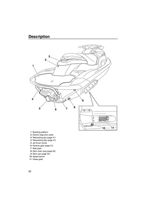 28
28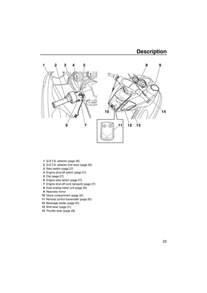 29
29 30
30 31
31 32
32 33
33 34
34 35
35 36
36 37
37 38
38 39
39 40
40 41
41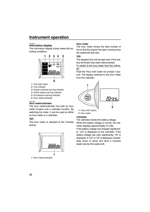 42
42 43
43 44
44 45
45 46
46 47
47 48
48 49
49 50
50 51
51 52
52 53
53 54
54 55
55 56
56 57
57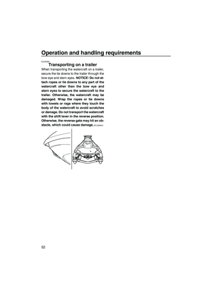 58
58 59
59 60
60 61
61 62
62 63
63 64
64 65
65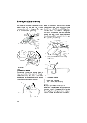 66
66 67
67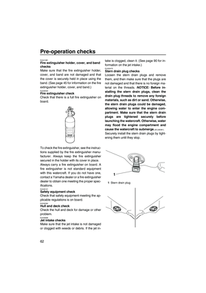 68
68 69
69 70
70 71
71 72
72 73
73 74
74 75
75 76
76 77
77 78
78 79
79 80
80 81
81 82
82 83
83 84
84 85
85 86
86 87
87 88
88 89
89 90
90 91
91 92
92 93
93 94
94 95
95 96
96 97
97 98
98 99
99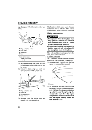 100
100 101
101 102
102 103
103