Page 25 of 78

INSTRUMENT AND CONTROL FUNCTIONS
4-6
2
345
6
7
8
9
start to move if the accelerator grip
is turned while the key is turned to
“ON”.
Speed warning indicator “SPEED”
If the vehicle speed exceeds 45 km/h,
the speed warning indicator appears
and the warning light flashes.
Operating status indicator “RUN”
This indicator appears when the vehi-
cle can be ridden.
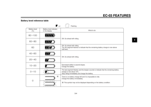
Battery level indicator
This indicator shows the remaining bat-
tery charge.
When only one battery indicator seg-
ment remains, recharge the battery as
soon as possible. (See page 3-3 for
more information about the battery lev-
el.)
TIPMake sure that the battery is sufficientlycharged before riding.
If the self-diagnosis detects a problem
with the battery, the warning light
comes on, the warning mark “ ” ap-
pears, and all segments of the battery
level indicator flash. The electric output
from the battery may also be reduced.
The vehicle can still be ridden, but it
must be checked by a Yamaha dealer
as soon as possible.
Warning light
This warning light comes on or flashes
as follows:
Speed warning indicator
The warning light flashes when vehicle
speed exceeds 45 km/h. At the same
time, the speed warning indicator
“SPEED” appears.
1. Battery level indicator
1
1. Battery level indicator
2. Warning light
3. Warning mark “ ”
2
1
3
1CB-9-EA.book 6 ページ 2012年4月11日 水曜日 午前9時34分
Page 26 of 78

INSTRUMENT AND CONTROL FUNCTIONS
4-7
1
2
34
5
6
7
8
9Error warnings
If a problem is detected, the warning
light comes on. In this case, check for
the warning mark “ ”. If this warning
mark also appears, have a Yamaha
dealer check the vehicle.
Warning mark “ ”
This warning mark flashes if a problem
is detected. If the warning mark keeps
flashing after turning the key to “OFF”
and then back to “ON”, have a Yamaha
dealer check the vehicle.TIPAfter turning the key to “ON”, the warn-
ing mark appears. If the warning mark
goes out after a few seconds, there isno malfunction. Go ahead with riding.
EAU50034
Using the security lock The EC-03 is equipped with a security
lock that can be used by registering a
security number. Once the security
number has been set, the vehicle can-
not be ridden unless the correct securi-
ty number is entered, even if the key is
turned to “ON”.
Registering and changing the secu-
rity number
WARNING
EWA15611
Be sure to stop the vehicle before
registering or changing the security
number. Changing settings while
riding can distract the operator andincrease the risk of an accident.TIPThe security number registration/
change mode is canceled if the regis-
tering procedure is not completed in
one minute. If the mode cancels, repeatthe procedure.
1. Turn the key to “ON”. All display segments appear for a
few seconds, then the vehicle en- ters the standby mode and
“PUSH” flashes.
TIPWhen the security lock has been
locked, the security number indicator
“ LOCK” appears when the vehicle isin the standby mode.
2. Change to the riding mode by pushing any of the buttons.1. Security lock indicator “ LOCK”
1
1CB-9-EA.book 7 ページ 2012年4月11日 水曜日 午前9時34分
Page 27 of 78

INSTRUMENT AND CONTROL FUNCTIONS
4-8
2
345
6
7
8
9
The display shows that the vehicle
is in the riding mode.
TIP
When the security lock is locked,
after changing to the riding mode,
enter the security number to un- lock the security lock. (See page
7-1 for more information about un-
locking the security lock.)
When the vehicle enters the riding
mode, the beeper sounds. The
beeper stops sounding when ei-
ther brake lever is squeezed or thevehicle starts moving.
3. Press buttons 2 and 3 simulta- neously.
The display changes to the securi-
ty lock registration mode.
Registering the security numberfor the first timeProceed to step 5.
Changing the security number“OLD” and “– – – – –” are dis-
played. 4. Use the buttons to enter the regis-
tered security number.
Proceed to step 5 if the correct se-
curity number is entered.
If an incorrect number is entered,
the beeper sounds, “NG” flashes
1. Button 1 “POWER”
2. Button 2 “SET”
3. Button 3 “SELECT”
12
3
1. Input number indicator “– – – – –”
2. Registered number indicator “OLD”
2
1
1CB-9-EA.book 8 ページ 2012年4月11日 水曜日 午前9時34分
Page 28 of 78
INSTRUMENT AND CONTROL FUNCTIONS
4-9
1
2
34
5
6
7
8
9for a few seconds, and the vehicle
returns to the riding mode. Repeat
the procedure from step 3.
5. “NEW” and “– – – – –” are dis- played. Enter a new security number.
The security number consists of a
four-digit number. Enter a number
using the buttons.
TIPThe number “1111” cannot be used as
a security number.
When a four-digit security number
has been entered, “OK or NG” is
displayed.
6. Push button 3 “SELECT” to display “OK”.
1. Incorrect number indicator “NG”
1
1. Input number indicator “– – – – –”
2. New number indicator “NEW”
21
1. Number confirmation indicator “OK”
1
1CB-9-EA.book 9 ページ 2012年4月11日 水曜日 午前9時34分
Page 29 of 78

INSTRUMENT AND CONTROL FUNCTIONS
4-10
2
345
6
7
8
9
7. Push button 2 “SET”. The security
number flashes for a few seconds,
and then the vehicle enters the
riding mode.
TIP
Be sure to record the security
number and keep it in a safe place.
Pushing button 3 “SELECT”
switches the display between “OK”
and “NG”.
To change the registered security
number, switch the display to “NG”
by pushing button 3 “SELECT”,
and then push button 2 “SET”. Re-peat the procedure from step 5. Locking and unlocking the security
lock
Locking the security lock
Push button 2 “SET” for a few seconds.
When the security lock is locked, the
security lock indicator “ LOCK” is dis-
played.TIPDo not lock the security lock when hav-
ing a Yamaha dealer perform service orrepairs on the vehicle.
Unlocking the security lockChange to the standby mode by push-
ing one of the buttons, then enter the security number. (See “Preparations
for starting off” on page 7-1.)1. Security lock indicator “ LOCK”
1
1CB-9-EA.book 10 ページ 2012年4月11日 水曜日 午前9時34分
Page 30 of 78
INSTRUMENT AND CONTROL FUNCTIONS
4-11
1
2
34
5
6
7
8
9
EAU1234A
Handlebar switches
EAU12460
Turn signal switch “ / ”
To signal a right-hand turn, push this
switch to “ ”. To signal a left-hand
turn, push this switch to “ ”. When re-
leased, the switch returns to the center
position. To cancel the turn signal
lights, push the switch in after it has re-
turned to the center position.
EAU12500
Horn switch “ ”
Press this switch to sound the horn.
EAU12901
Front brake lever The front brake lever is located on the
right side of the handlebar. To apply the
front brake, pull this lever toward the
throttle grip.
EAU12951
Rear brake lever The rear brake lever is located on the
left side of the handlebar. To apply the
rear brake, pull this lever toward the
handlebar grip.
1. Turn signal switch “ / ”
2. Horn switch “ ”
1
2
1. Front brake lever
1
1. Rear brake lever
1
1CB-9-EA.book 11 ページ 2012年4月11日 水曜日 午前9時34分
Page 31 of 78
INSTRUMENT AND CONTROL FUNCTIONS
4-12
2
345
6
7
8
9
EAUT3170
Seat To open the seat1. Place the vehicle on the center- stand.
2. Insert the key in the lock, and then turn it clockwise.
3. Fold the seat up. To close the seat
1. Fold the seat down, and then push it down to lock it in place.
2. Remove the key.
TIPMake sure that the seat is properly se-cured before riding.
EAU50060
Helmet holder The helmet holder is located under the
seat. A helmet holding cable is provid-
ed under the seat to secure a helmet to
the helmet holder.
To secure a helmet to the helmet
holder 1. Open the seat. (See page 4-12.)
2. Pass the helmet holding cable through the buckle on the helmet
strap as shown, and then hook the
end of the helmet holding cable
over the helmet holder.
3. Securely close the seat. WARN- ING! Never ride with a helmet at-
1. Unlock.
1
1. Helmet holding cable
2. Helmet holder
1
2
1CB-9-EA.book 12 ページ 2012年4月11日 水曜日 午前9時34分
Page 32 of 78
INSTRUMENT AND CONTROL FUNCTIONS
4-13
1
2
34
5
6
7
8
9tached to the helmet holder,
since the helmet may hit ob-
jects, causing loss of control
and possibly an accident.
[EWA10161]
To release the helmet from the hel-
met holder
Open the seat, remove the helmet
holding cable from the helmet holder
and the helmet, and then close the
seat.
EAUT1072
Luggage hook
WARNING
EWAT1031
Do not exceed the load limit of 1
kg (2 lb) for the luggage hook.
Do not exceed the maximum
load of 87 kg (192 lb) for the ve-hicle.
EAU29910
Grab bar Hold the grab bar with your right hand
to place the vehicle on the centerstand.
1. Luggage hook1
1. Grab bar
1
1CB-9-EA.book 13 ページ 2012年4月11日 水曜日 午前9時34分


![YAMAHA EC-03 2012 Owners Manual INSTRUMENT AND CONTROL FUNCTIONS
4-13
1
2
34
5
6
7
8
9tached to the helmet holder,
since the helmet may hit ob-
jects, causing loss of control
and possibly an accident.
[EWA10161]
To release the hel](/manual-img/51/49457/w960_49457-31.png "YAMAHA EC-03 2012 Owners Manual INSTRUMENT AND CONTROL FUNCTIONS
4-13
1
2
34
5
6
7
8
9tached to the helmet holder,
since the helmet may hit ob-
jects, causing loss of control
and possibly an accident.
[EWA10161]
To release the hel")