Page 315 of 400

08 Maintenance and service
Engine compartment
08
313
Turn the handle about 20-25 degrees
clockwise. You will hear when the catch
releases.
Move the catch to the left and open the
bonnet. (The catch hook is located
between the headlamp and grille, see illus-
tration.)
WARNING
Check that the bonnet locks properly when
closed.
Engine compartment, overview
The appearance of the engine compartment may
vary depending on engine variant.
Coolant expansion tank
Power steering fluid reservoir
Engine oil dipstick1
Radiator
Filling engine oil
Reservoir for brake and clutch fluid
(located on the driver's side)
Battery
Relay and fuse box
Filling washer fluid
Air filter
WARNING
The ignition system has very high voltage
and output. The voltage in the ignition sys-
tem is highly dangerous. The remote control
key must always be in 0 position when work
is being done in the engine compartment,
see page 80.
Do not touch the spark plugs or ignition coil
when the remote control key is in II position
or when the engine is hot.
Checking the engine oil
1Engines with electronic oil level sensor have no dipstick (5-cyl. diesel).
ProCarManuals.com
Page 319 of 400

08 Maintenance and service
Engine compartment
08
317
For capacities and for standards regarding
water quality, see page 361.
Check the coolant regularlyThe level must lie between the MIN and MAX
marks on the expansion tank. If the system is
not filled sufficiently, high temperatures could
occur, causing a risk of damage to the engine.
IMPORTANT
•A high content of chlorine, chlorides
and other salts may cause corrosion in
the cooling system.
•Always use coolant with anti-corrosion
agent as recommended by Volvo.
•Ensure that the coolant mixture is 50%
water and 50% coolant.
•Mix the coolant with approved quality
tap water. In the event of any doubt
about water quality, used ready-mixed
coolant in accordance with Volvo rec-
ommendations.
•When changing coolant/replacing cool-
ing system components, flush the cool-
ing system clean with approved quality
tap water or flush with ready-mixed
coolant.
•The engine must only be run with a well-
filled cooling system. Otherwise, tem-
peratures that are too high may occur
resulting in the risk of damage (cracks)
in the cylinder head.
Brake and clutch fluid
Checking the levelBrake and clutch fluid have a common reser-
voir. The level must be between the MIN and
MAX marks that are visible inside the reservoir.
Check the level regularly.
Change the brake fluid every other year or at
every other regular service.
For capacities and recommended fluid grade,
see page 361. The fluid should be changed
annually on cars driven in conditions requiring
hard, frequent braking, such as driving in
mountains or tropical climates with high
humidity.
WARNING
If the brake fluid is under the MIN level in the
brake fluid reservoir, do not drive further
before topping up the brake fluid. Volvo rec-
ommends that the reason for the loss of
brake fluid is investigated by an authorised
Volvo workshop.
ProCarManuals.com
Page 320 of 400

08 Maintenance and service
Engine compartment
08
318
Filling
Brake fluid reservoir location.
The fluid reservoir is protected under the cover
over the cold zone in the engine compartment.
The round cover must be removed first before
the reservoir cap can be reached.
1. Turn and open the cover located on the
covering.
2. Unscrew the reservoir cap and fill the fluid.
The level must be between the MIN and
MAX marks, which are located on the
inside of the reservoir.
IMPORTANT
Do not forget to refit the cap.
Power steering fluid
IMPORTANT
Keep the area around the power steering
fluid reservoir clean when checking. The
cover must not be opened.
Check the level frequently. The fluid does not
require changing. The fluid level must be
between the MIN and MAX marks. For capaci-
ties and recommended fluid grade, see
page 361.
NOTE
If a fault should arise in the power steering
system or if the engine is switched off and
the car must be towed, it can still be steered.
ProCarManuals.com
Page 321 of 400

08 Maintenance and service
Lamps
08
319 General
All bulbs are specified, see page 324. The fol-
lowing list contains locations of bulbs and
other light sources that are specialised or
unsuitable for changing except at a workshop:
•Active Xenon headlamps - ABL (Xenon
lamps)
•Direction indicators, door mirrors
•Approach lighting, door mirrors
•Courtesy lighting
•Glovebox lighting
•General interior lighting in the roof
•Reading lamps
•Side position, position lamps rear
•Brake light
•LED lights, general
WARNING
On cars with Xenon headlamps, the
replacement of Xenon lamps must be car-
ried out at a workshop - an authorised Volvo
workshop is recommended. Working with
Xenon lamps demands extreme caution
because the headlamp is equipped with a
high voltage unit.
IMPORTANT
Never touch the glass part of the bulbs with
your fingers. Grease and oils from your fin-
gers are vaporised by the heat, coating the
reflector and then causing damage.
Headlamps front
All of the headlamp bulbs are replaced via the
engine compartment. Loosen and remove the
whole headlamp.
WARNING
The remote control key must not be turned
to key position I or II during bulb replace-
ment.
See the section "Key positions" - for a
description of the remote control key's 3 key
positions.
Removing the headlamp1. Make sure the remote control key is in key
position 0, see page 80:
2. (First illustration)
ProCarManuals.com
Page 324 of 400

08 Maintenance and service
Lamps
08
322
Direction indicators/flashers
1. Detach the headlamp.
2. Detach the cover by pulling it straight out.
3. Pull the bulb holder in order to extract the
bulb.
4. Press and simultaneously turn the bulb to
detach it.
Reinstall the parts in reverse order.
Lamp housing, rear
The reversing, fog and direction indicator bulbs
in the rear lamp cluster are replaced from inside
the cargo area.
1. Open the panel.
2. Remove the insulation that is fitted in front
of the bulb holder by pulling it straight out.
3. Press down the catch and pull out the bulb
holder.
4. Remove the blown bulb by pressing it in
and turning anticlockwise.
5. Fit a new bulb, press down and turn clock-
wise.
6. Press down the catch when the bulb holder
is refitted.7. Refit the insulation and panel.
NOTE
If an error message remains after the broken
bulb has been replaced then we recom-
mend that you visit an authorised Volvo
workshop.
Location of rear bulbs
Lamp lens, right-hand side
Brake light (LED)
Direction indicators
Reversing lamp
Rear fog lamp (driver's side)
ProCarManuals.com
Page 333 of 400
 the more
the batteries must be charged =
increased fuel consumption.
•When")
08 Maintenance and service
Battery
08
331
NOTE
•The higher the current take-off in the car
(extra cooling/heating, etc.) the more
the batteries must be charged =
increased fuel consumption.
•When the capacity of the battery has
fallen below the lowest permissible level
then the Start/Stop function is disen-
gaged.
Temporarily reduced Start/Stop function due
to high current take-off means:
•The engine starts automatically2 without
the driver depressing the clutch pedal
(manual gearbox).
•The engine starts automatically without the
driver lifting his/her foot off the foot brake
pedal (automatic gearbox).
Location of the batteries
A: Left-hand drive car. B: Right-hand drive car. 1.
Battery for starting3 2. Support battery.
The support battery normally requires no more
service than the normal battery that is used for
starting. A workshop should be contacted in
the event of questions or problems - an author-
ised Volvo workshop is recommended.
IMPORTANT
If the following instruction is not observed
then the Start/Stop function may temporar-
ily cease to work after the connection of an
external battery or battery charger:
•The negative battery terminal on the
car's main battery must never be used
for connecting an external battery or
battery charger - only the car chassis
may be used as the grounding point.
See the section "Start assistance" - for a
description of how the cable clamps must
be attached.
2Automatic starting can only take place if the gear lever is in neutral position.3The battery for starting is described in detail on page 328.
ProCarManuals.com
Page 342 of 400
08 Maintenance and service
Fuses
08
340* Option/accessory, for more information, see Introduction.
Box BFunctionA
--
Brake light5
Sunroof*20
Immobiliser5
ProCarManuals.com
Page 343 of 400
08 Maintenance and service
Fuses
08
��
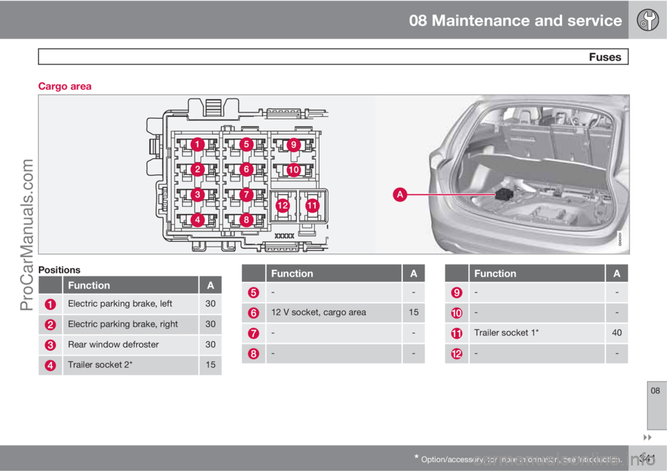
* Option/accessory, for more information, see Introduction.341 Cargo area
Positions
FunctionA
Electric parking brake, left30
Electric parking brake, right30
Rear window defroster30
Trailer socket 2*15
FunctionA
--
12 V socket, cargo area15
--
--
FunctionA
--
--
Trailer socket 1*40
--
ProCarManuals.com