Page 214 of 520

214 2-1. Driving procedures
CAUTION
■To avoid an accident
Do not hang objects on or attach objects to the shift lever.
Doing so may cause the shift lever to move and the shift position to change.
■ For the shift lever
Do not remove the shift lever knob or use anything but a genuine Toyota shift
lever knob. Also, do not hang anything on the shift lever.
Doing so could prevent the shift lever from returning to position, causing
unexpected accidents to occur when the vehicle is in motion.
■ P position switch
Do not press the P position switch while the vehicle is moving.
If the P position switch is pressed when driving at very low speeds (for
example, directly before stopping the vehicle), the vehicle may stop sud-
denly when the shift position switches to P, which could lead to an accident.
NOTICE
■Situations where P position control system malfunctions are possible
If any of the following situations occur, P position control system malfunc-
tions are possible.
Immediately stop the vehicle in a safe place on level ground, apply the park-
ing brake, and then contact your Toyota dealer.
●When the “P Lock Malfunction” warning message appears on the multi-
information display. (
P. 429)
● When the shift position symbols (such as P and R) are extinguished and
the frames surrounding the shift position symbols are flashing on the shift
position indicator.
● When the shift position indicator remains off.
■ Notes regarding shift lever an d P position switch operation
Avoid repeatedly operating the shift lever and P position switch in quick suc-
cession.
The system protection function may activate and it will not be temporarily
possible to shift the shift position other than P. If this happens, please wait
for a while before attempting to change the shift position again.
Page 218 of 520
218
2-2. Instrument cluster
Gauges and meters
The following gauges, meters and displays illuminate when the
“POWER” switch is in ON mode.EV System Indicator
Displays the EV system output or regeneration level.
SOC (State of Charge) gauge
Displays the amount of charge remaining in the traction battery.
Driving range
Displays an estimated drivable distance according to the climate setting
and the amount of charge remaining in the traction battery.
(P. 30, 276)
Speedometer
Displays the vehicle speed.
Multi-informat ion display
Presents the driver with a variety of driving-related data ( P. 227)
Page 219 of 520
219
2-2. Instrument cluster
2
When driving
Instrument panel light control
The brightness of the instrument panel lights can be adjusted.
Brighter
Darker
Odometer/trip meter
Odometer
Displays the total distance the vehicle has been driven.
Tr i p m e t e r
Displays the distance the vehicle has been driven since the meter was
last reset. Trip meters A and B can be used to record and display differ-
ent distances independently.
Display change button
Performs odometer, trip meter and meter display customization.
While the trip meter is being displayed: Pressing and holding the button
will reset the trip meter.
While the odometer is being displayed: Pressing and holding the button
enables Eco Driving Indicator Light and the turn-by-turn navigation to
be activated or deactivated.
Page 220 of 520
220 2-2. Instrument cluster
Eco Driving Indicator Light and turn-by-turn navigation display
customization
While the odometer is being displayed, customization can be per-
formed by pressing and holding the display change button.
Each time the display change button is pressed, ECO Driving Indi-
cator Light display is activated or deactivated.
If OFF is selected, the Eco Driving Indicator Light will not be displayed.
Each time the display change button is pressed, the turn-by-turn
navigation is activa ted or deactivated.
If OFF is selected, the turn-by-turn navigation display will not be dis-
played.
When settings have been completed, press and hold the display
change button until the odometer is displayed.
Page 221 of 520

221
2-2. Instrument cluster
2
When driving
■
The meters and display illuminate when
The “POWER” switch is in ON mode.
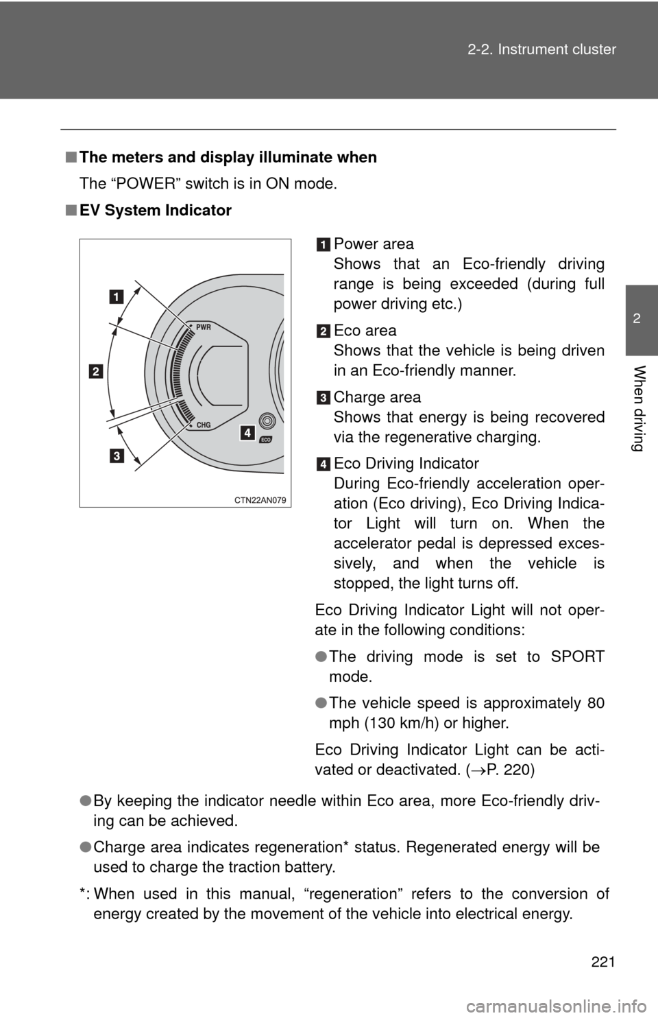
■ EV System Indicator
●By keeping the indicator needle within Eco area, more Eco-friendly driv-
ing can be achieved.
● Charge area indicates regeneration* status. Regenerated energy will be
used to charge the traction battery.
*: When used in this manual, “regeneration” refers to the conversion of energy created by the movement of the vehicle into electrical energy.
Power area
Shows that an Eco-friendly driving
range is being exceeded (during full
power driving etc.)
Eco area
Shows that the vehicle is being driven
in an Eco-friendly manner.
Charge area
Shows that energy is being recovered
via the regenerative charging.
Eco Driving Indicator
During Eco-friendly acceleration oper-
ation (Eco driving), Eco Driving Indica-
tor Light will turn on. When the
accelerator pedal is depressed exces-
sively, and when the vehicle is
stopped, the light turns off.
Eco Driving Indicator Light will not oper-
ate in the following conditions:
● The driving mode is set to SPORT
mode.
● The vehicle speed is approximately 80
mph (130 km/h) or higher.
Eco Driving Indicator Light can be acti-
vated or deactivated. ( P. 220)
Page 227 of 520
227
2-2. Instrument cluster
2
When driving
Multi-information display
The multi-information display presents the driver with a variety of
driving-related data.
● Trip information ( P. 229)
Displays driving range, power
consumption and other cruis-
ing-related information.
● Warning messages
( P. 427)
Automatically displayed when
a malfunction occurs in one of
the vehicle’s systems.
Page 228 of 520
228 2-2. Instrument cluster
■Display contents
Each time the “DISP” switch is pressed, the menu screen changes.
When the desired menu screen is displayed, stop pressing the
“DISP” switch. The details screen will soon be displayed.
*: Not shown when no destination is set or when the turn-by-turn naviga- tion display is not activated. ( P. 220, 231).
Trip information contentsSwitching display items
Driving range
Press the “DISP” switch.
Turn-by-turn navigation*
Efficiency
Trip efficiency
ECO coach
CO2 reduction
Aux power
Page 229 of 520
229
2-2. Instrument cluster
2
When driving
Trip information
■ Driving range
Displays an estimated driving range according to the
amount of charge remaining in the traction battery
and air conditioning settings.Displays what the estimated maximum driving
range is with the air conditioning system off
according to the amount of charge remaining in the
traction battery.
Displays the amount the estimated maximum driv-
ing range is shortened acco rding to current air con-
ditioning mode.
The climate setting is linked to the air conditioning sys-
tem, and changes according to air conditioning settings.
( P. 276)
The estimated maximum driving range is only an esti-
mate. According to driving conditions, the actual driving
range may differ. Keep early charging in mind.
The driving range according to current air conditioning
mode is displayed in the left section of the instrument
cluster. ( P. 218)