2012 TOYOTA IQ inflation pressure
[x] Cancel search: inflation pressurePage 415 of 476
5
415 5-2. Steps to take in an emergency
When trouble arises
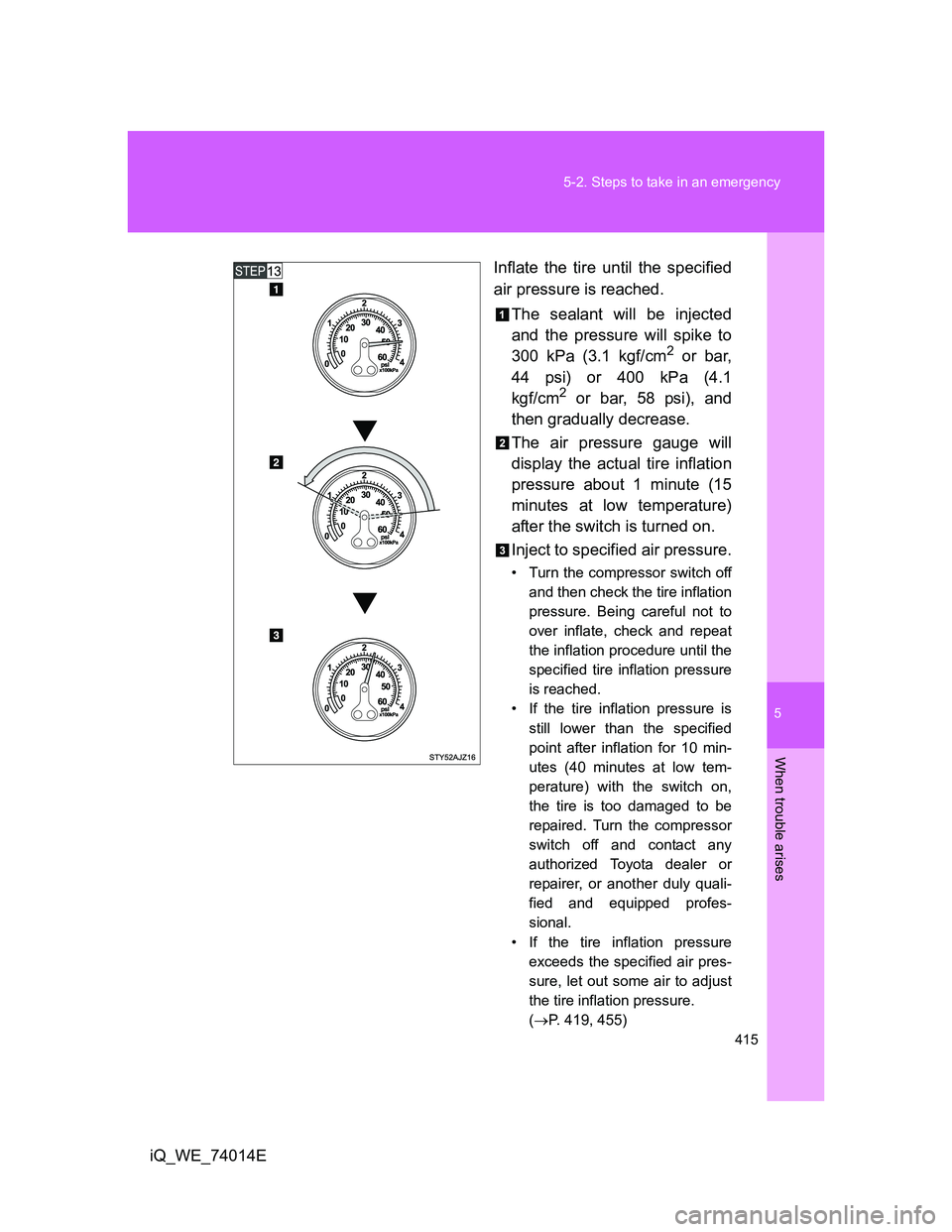
iQ_WE_74014EInflate the tire until the specified
air pressure is reached.
The sealant will be injected
and the pressure will spike to
300 kPa (3.1 kgf/cm
2 or bar,
44 psi) or 400 kPa (4.1
kgf/cm
2 or bar, 58 psi), and
then gradually decrease.
The air pressure gauge will
display the actual tire inflation
pressure about 1 minute (15
minutes at low temperature)
after the switch is turned on.
Inject to specified air pressure.
• Turn the compressor switch off
and then check the tire inflation
pressure. Being careful not to
over inflate, check and repeat
the inflation procedure until the
specified tire inflation pressure
is reached.
• If the tire inflation pressure is
still lower than the specified
point after inflation for 10 min-
utes (40 minutes at low tem-
perature) with the switch on,
the tire is too damaged to be
repaired. Turn the compressor
switch off and contact any
authorized Toyota dealer or
repairer, or another duly quali-
fied and equipped profes-
sional.
• If the tire inflation pressure
exceeds the specified air pres-
sure, let out some air to adjust
the tire inflation pressure.
(P. 419, 455)
Page 417 of 476
5
417 5-2. Steps to take in an emergency
When trouble arises
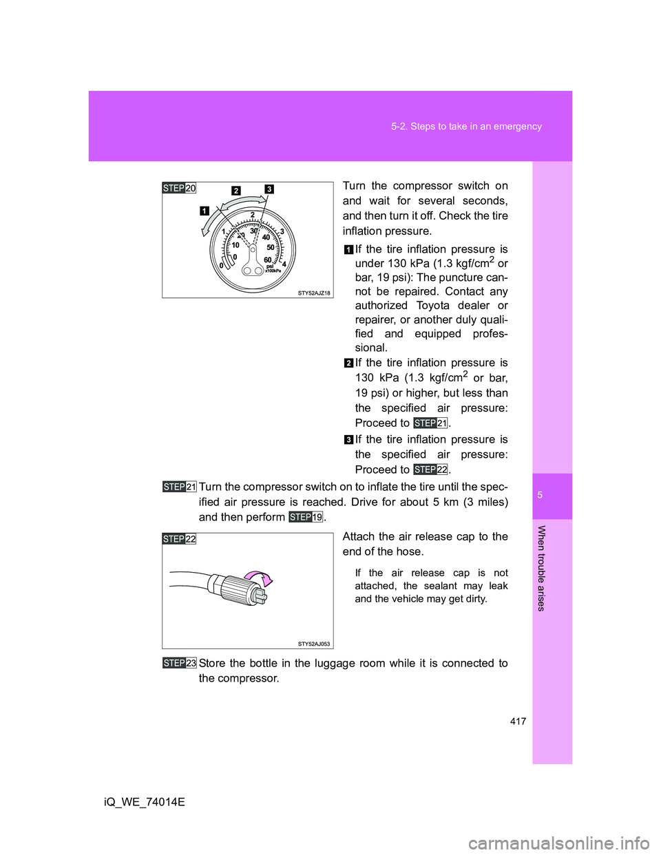
iQ_WE_74014ETurn the compressor switch on
and wait for several seconds,
and then turn it off. Check the tire
inflation pressure.
If the tire inflation pressure is
under 130 kPa (1.3 kgf/cm
2 or
bar, 19 psi): The puncture can-
not be repaired. Contact any
authorized Toyota dealer or
repairer, or another duly quali-
fied and equipped profes-
sional.
If the tire inflation pressure is
130 kPa (1.3 kgf/cm
2 or bar,
19 psi) or higher, but less than
the specified air pressure:
Proceed to .
If the tire inflation pressure is
the specified air pressure:
Proceed to .
Turn the compressor switch on to inflate the tire until the spec-
ified air pressure is reached. Drive for about 5 km (3 miles)
and then perform .
Attach the air release cap to the
end of the hose.
If the air release cap is not
attached, the sealant may leak
and the vehicle may get dirty.
Store the bottle in the luggage room while it is connected to
the compressor.
Page 419 of 476
5
419 5-2. Steps to take in an emergency
When trouble arises
iQ_WE_74014E
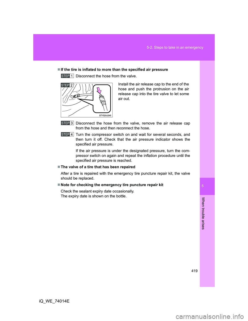
If the tire is inflated to more than the specified air pressure
Disconnect the hose from the valve.
Disconnect the hose from the valve, remove the air release cap
from the hose and then reconnect the hose.
Turn the compressor switch on and wait for several seconds, and
then turn it off. Check that the air pressure indicator shows the
specified air pressure.
If the air pressure is under the designated pressure, turn the com-
pressor switch on again and repeat the inflation procedure until the
specified air pressure is reached.
The valve of a tire that has been repaired
After a tire is repaired with the emergency tire puncture repair kit, the valve
should be replaced.
Note for checking the emergency tire puncture repair kit
Check the sealant expiry date occasionally.
The expiry date is shown on the bottle.
Install the air release cap to the end of the
hose and push the protrusion on the air
release cap into the tire valve to let some
air out.
Page 421 of 476
5
421 5-2. Steps to take in an emergency
When trouble arises
iQ_WE_74014E
CAUTION
When fixing the flat tire
If the hose comes off the valve while inflating the tire, there is a risk that
the hose will move abruptly due to air pressure.
After inflation of the tire has completed, the sealant may splatter when the
hose is disconnected or some air is let out of the tire.
Follow the operation procedure to repair the tire. If the procedures not fol-
lowed, the sealant may spray out.
Keep back from the tire while it is being repaired, as there is a chance of it
bursting while the repair operation is being performed. If you notice any
cracks or deformation of the tire, turn off the compressor switch and stop
the repair operation immediately.
The repair kit may overheat if operated for a long period of time. Do not
operate the repair kit continuously for more than 60 minutes.
Parts of the repair kit become hot during operation. Be careful handling the
repair kit during and after operation. Do not touch the metal part connect-
ing the bottle and the compressor. It will be extremely hot.
Do not attach the vehicle speed warning sticker to an area other than the
one indicated. If the sticker is attached to an area where an SRS airbag is
located, such as the pad of the steering wheel, it may prevent the SRS air-
bag from operating properly.
Driving to spread the liquid sealant evenly
Observe the following precautions to reduce the risk of accidents.
Failing to do so may result in a loss of vehicle control and cause death or
serious injury.
Drive the vehicle carefully at a low speed. Be especially careful when turn-
ing and cornering.
If the vehicle does not drive straight or you feel a pull through the steering
wheel, stop the vehicle and check the following.
• Tire condition. The tire may have separated from the wheel.
• Tire inflation pressure. If the tire inflation pressure is 130 kPa (1.3
kgf/cm
2 or bar, 19 psi) or less, the tire may be severely damaged.
Page 455 of 476

455 6-1. Specifications
6
Vehicle specifications
iQ_WE_74014E
Brakes
*1: Minimum pedal clearance when depressed with a force of 300 N (30 kgf, 66
lbf) while the engine is running
*2: Parking brake lever travel when pulled up with a force of 200 N (20 kgf, 44
lbf)
Steering
Tires and wheels
Pedal clearance*1
Vehicles with rear drum brake
Vehicles with rear disc brake91 mm (3.58 in.) Min.
86 mm (3.39 in.) Min.
Pedal free play 1 6 mm (0.04 0.24 in.)
Parking brake lever travel*2
Vehicles with rear drum brake
Vehicles with rear disc brake6 9 clicks
5 8 clicks
Fluid type SAE J1703 or FMVSS No.116 DOT 3
Free play Less than 30 mm (1.2 in.)
Tire size 175/65R15 84S, 175/60R16 82H
Tire inflation pressure
(Recommended cold tire
inflation pressure)Vehicle
speedFront wheel
kPa (kgf/cm
2
or bar, psi)Rear wheel
kPa (kgf/cm2
or bar, psi)
More than
160 km/h
(100 mph)240 (2.4, 35) 230 (2.3, 33)
160 km/h
(100 mph)
or less230 (2.3, 33) 220 (2.2, 32)
Wheel size 15 5 J, 16 5 J
Wheel nut torque 103 N·m (10.5 kgf·m, 76 ft·lbf)
Page 469 of 476

469 Alphabetical index
iQ_WE_74014E
Switch
Airbag manual on-off
switch.................................. 159
Emergency flasher switch ..... 386
Engine switch ................ 176, 179
Fog light switch ..................... 216
Hazard light switch ................ 386
Ignition switch ............... 176, 179
Light switches ....................... 211
Outside rear view mirror
switch.................................... 95
Power door lock switch ........... 73
Power window switch ............ 100
Rear window wiper and
washer switch ..................... 222
VSC OFF switch ................... 225
Window lock switch ............... 100
Wiper and washer
switch.......................... 218, 222
Tachometer .............................. 197
Tail lights
Replacing light bulbs ............. 374
Switch ................................... 211
Wattage................................. 456
Theft deterrent system
Alarm..................................... 119
Engine immobilizer system ... 108
Tire inflation pressure ............. 350
Tires
Chains ................................... 233
Checking ............................... 347
If you have a flat tire.............. 405
Inflation pressure .......... 350, 455
Rotating tires ......................... 347
Size ....................................... 455
Snow tires ............................. 231
Tools ......................................... 324
Towing
Emergency towing ................ 389
Trailer towing ........................ 235Traction control ....................... 224
TRC ........................................... 224
Trip information ....................... 205
Trip meter ................................. 206
Turn signal lights
Lever ..................................... 193
Replacing light bulbs............. 373
Wattage ................................ 456
Vanity mirrors .......................... 294
Vehicle identification
number ................................... 445
Vehicle stability control .......... 224
VSC ........................................... 224
Warning buzzers
Brake system ........................ 397
Seat belt reminder ................ 399
Warning lights
ABS....................................... 398
Airbag system ....................... 398
Anti-lock brake system.......... 398
Brake assist system .............. 398
Brake system ........................ 397
Charging system ................... 398
Electric power steering ......... 398
Engine oil pressure ............... 398
High engine coolant
temperature ........................ 398
Low fuel level ........................ 399
Malfunction indicator lamp .... 398
Open door ............................. 399
Pretensioners........................ 398
Seat belt reminder light ......... 399
Slip indicator ......................... 398
Smart entry & start system ... 401
SRS airbags.......................... 398
VSC OFF .............................. 398
Warning reflector holder ......... 301
T
V
W
Page 476 of 476
476
iQ_WE_74014E
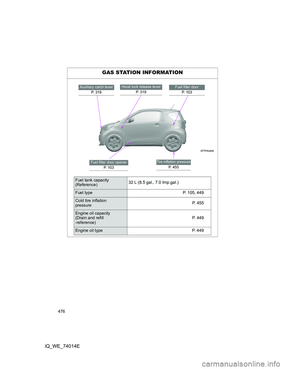
GAS STATION INFORMATION
Auxiliary catch lever
P. 319Fuel filler door
P. 1 0 3Hood lock release lever
P. 3 1 9
Fuel filler door opener
P. 103Tire inflation pressure
P. 455
Fuel tank capacity
(Reference)32 L (8.5 gal., 7.0 Imp.gal.)
Fuel type P. 105, 449
Cold tire inflation
pressureP. 4 5 5
Engine oil capacity
(Drain and refill
-reference)P. 4 4 9
Engine oil type P. 449