2012 SUBARU TRIBECA ECU
[x] Cancel search: ECUPage 72 of 420
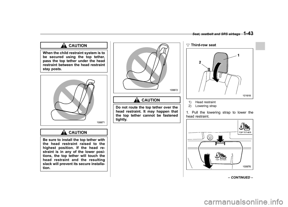
CAUTION
When the child restraint system is to
be secured using the top tether,
pass the top tether under the head
restraint between the head restraint
stay posts.
CAUTION
Be sure to install the top tether with
the head restraint raised to the
highest position. If the head re-
straint is in any of the lower posi-
tions, the top tether will touch the
head restraint and the resulting
slack will prevent its secure installa-tion.
CAUTION
Do not route the top tether over the
head restraint. It may happen that
the top tether cannot be fastened
tightly. !
Third-row seat1) Head restraint
2) Lowering strap
1. Pull the lowering strap to lower the
head restraint.
Seat, seatbelt and SRS airbags 1-43
– CONTINUED –
Page 73 of 420
1-44Seat, seatbelt and SRS airbags
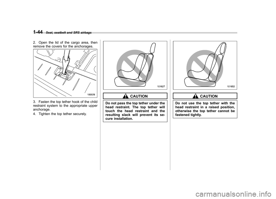
2. Open the lid of the cargo area, then
remove the covers for the anchorages.
3. Fasten the top tether hook of the child
restraint system to the appropriate upperanchorage.
4. Tighten the top tether securely.
CAUTION
Do not pass the top tether under the
head restraint. The top tether will
touch the head restraint and the
resulting slack will prevent its se-
cure installation.CAUTION
Do not use the top tether with the
head restraint in a raised position,
otherwise the top tether cannot be
fastened tightly.
Page 75 of 420

1-46Seat, seatbelt and SRS airbags
refer to “Seatbelts ”F 1-17.
. Do not sit or lean unnecessarily
close to the SRS airbag. Because
the SRS airbag deploys with
considerable speed –faster than
the blink of an eye –and force to
protect in high speed collisions,
the force of an airbag can injure
an occupant whose body is too
close to SRS airbag.
It is also important to wear your
seatbelt to help avoid injuries
that can result when the SRS
airbag contacts an occupant not
in proper position such as one
thrown forward during pre-acci-
dent braking.
Even when properly positioned,
there remains a possibility that
an occupant may suffer minor
injury such as abrasions and
bruises to the face or arms
because of the SRS airbag de-
ployment force.
. The SRS airbags deploy with
considerable speed and force.
Occupants who are out of proper
position when the SRS airbag
deploys could suffer very serious
injuries. Because the SRS airbag
needs enough space for deploy- ment, the driver should always
sit upright and well back in the
seat as far from the steering
wheel as practical while still
maintaining full vehicle control
and the front passenger should
move the seat as far back as
possible and sit upright and well
back in the seat.
. Do not place any objects over or
near the SRS airbag cover or
between you and the SRS airbag.
If the SRS airbag deploys, those
objects could interfere with its
proper operation and could be
propelled inside the vehicle and
cause injury.WARNING
. Put children aged 12 and under in
a rear seat properly restrained at
all times. The SRS airbag de-
ploys with considerable speed
and force and can injure or even
kill children, especially if they are
12 years of age and under and
are not restrained or improperly
restrained. Because children are
lighter and weaker than adults,
their risk of being injured from
deployment is greater.
Consequently, we strongly re-
commend that ALL children (in-
cluding those in child seats and
those that have outgrown child
restraint devices) sit in a REAR
seat properly restrained at all
times in a child restraint device
or in a seatbelt, whichever is
appropriate for the child ’s age,
height and weight.
Always secure ALL types of child
restraint devices (including for-
ward facing child seats) in one of
the rear seating positions recom-
mended in this Owner ’s Manual.
According to accident statistics,
children are safer when properly
Page 104 of 420

Keys..................................................................... 2-2
Key number plate ................................................ 2-2
Immobilizer .......................................................... 2-3
Security ID plate .................................................. 2-3
Security indicator light ........................................ 2-4
Key replacement ................................................. 2-4
Door locks ........................................................... 2-5
Locking and unlocking from the outside .. ............ 2-5
Locking and unlocking from the inside ................ 2-5
Battery drainage prevention function ................... 2-6
Power door locking switches ............................. 2-7
Key lock-in prevention function ........................... 2-8
Remote keyless entry system ............................ 2-8
Locking the doors ............................................... 2-9
Unlocking the doors ........................................... 2-10
Unlocking the rear gate ...................................... 2-10
Illuminated entry ................................................ 2-10
Vehicle finder function ........................................ 2-10
Sounding a panic alarm ...................................... 2-11
Selecting audible signal operation ...................... 2-11
Replacing the battery ......................................... 2-11 Replacing lost transmitters
................................ 2-12
Alarm system ..................................................... 2-16
System operation ............................................... 2-16
Activating and deactivating the alarm system ..... 2-16
If you have accidentally triggered the alarm system ............................................................ 2-17
Arming the system ............................................ 2-17
Disarming the system ........................................ 2-18
Valet mode ........................................................ 2-18
Passive arming .................................................. 2-19
Tripped sensor identification .............................. 2-20
Shock sensors (dealer option).. .......................... 2-20
Child safety locks .............................................. 2-21
Windows ............................................................. 2-21
Power windows ................................................. 2-21
Rear gate ............................................................ 2-24
Moonroof (if equipped) ...................................... 2-25
Tilt function ....................................................... 2-26
Sliding function ................................................. 2-26
Anti-entrapment function .................................... 2-26
Sun shade ......................................................... 2-27 Keys and doors
2
Page 105 of 420
2-2Keys and doors
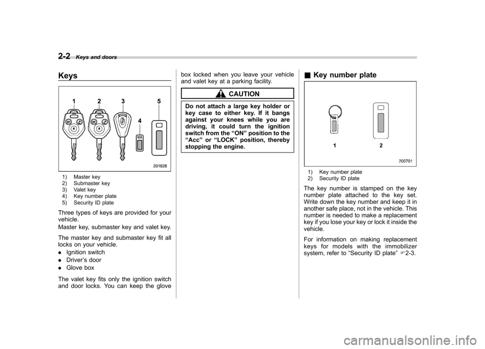
Keys
1) Master key
2) Submaster key
3) Valet key
4) Key number plate
5) Security ID plate
Three types of keys are provided for your vehicle.
Master key, submaster key and valet key.
The master key and submaster key fit all
locks on your vehicle. . Ignition switch
. Driver ’s door
. Glove box
The valet key fits only the ignition switch
and door locks. You can keep the glove box locked when you leave your vehicle
and valet key at a parking facility.
CAUTION
Do not attach a large key holder or
key case to either key. If it bangs
against your knees while you are
driving, it could turn the ignition
switch from the “ON ”position to the
“ Acc ”or “LOCK ”position, thereby
stopping the engine. &
Key number plate
1) Key number plate
2) Security ID plate
The key number is stamped on the key
number plate attached to the key set.
Write down the key number and keep it in
another safe place, not in the vehicle. This
number is needed to make a replacement
key if you lose your key or lock it inside thevehicle.
For information on making replacement
keys for models with the immobilizer
system, refer to “Security ID plate ”F 2-3.
Page 106 of 420
Immobilizer
CAUTION
FCC WARNING
Changes or modifications not ex-
pressly approved by the party re-
sponsible for compliance could void
the user ’s authority to operate the
equipment.
The immobilizer system is designed to
prevent an unauthorized person from
starting the engine. Only keys registered
with your vehicle ’s immobilizer system can
be used to operate your vehicle. Even if
an unregistered key fits into the ignition
switch and can be turned to the “START ”
position, the engine will automatically stop
after several seconds.
Each immobilizer key contains a trans-
ponder in which the key ’s ID code is
stored. When a key is inserted into the
ignition switch and turned to the “ON ”
position, the transponder transmits thekey ’s ID code to the immobilizer system ’s
receiver. If the transmitted ID code
matches the ID code registered in the
immobilizer system, the system allows the
engine to be started. Since the ID code is
transmitted and acted upon almost in- stantly, the immobilizer system does not
impede normal starting of the engine.
If the engine does not start, pull out the
key once before trying again. Refer to“
Ignition switch ”F 3-3.
This device complies with Part 15 of
the FCC Rules and RSS-Gen of IC
Rules. Operation is subject to the
following two conditions: (1) this de-
vice may not cause harmful interfer-
ence, and (2) this device must accept
any interference received, including
interference that may cause undesiredoperation.
CAUTION
. Do not place the key under direct
sunlight or anywhere it may
become hot.
. Do not get the key wet. If the key
gets wet, wipe it dry with a cloth
immediately.
NOTE
To protect your vehicle from theft,
please pay close attention to the fol-
lowing security precautions. . Never leave your vehicle unattended
with its keys inside. . Before leaving your vehicle, close all windows and lock the doors and reargate..
Do not leave spare keys or any
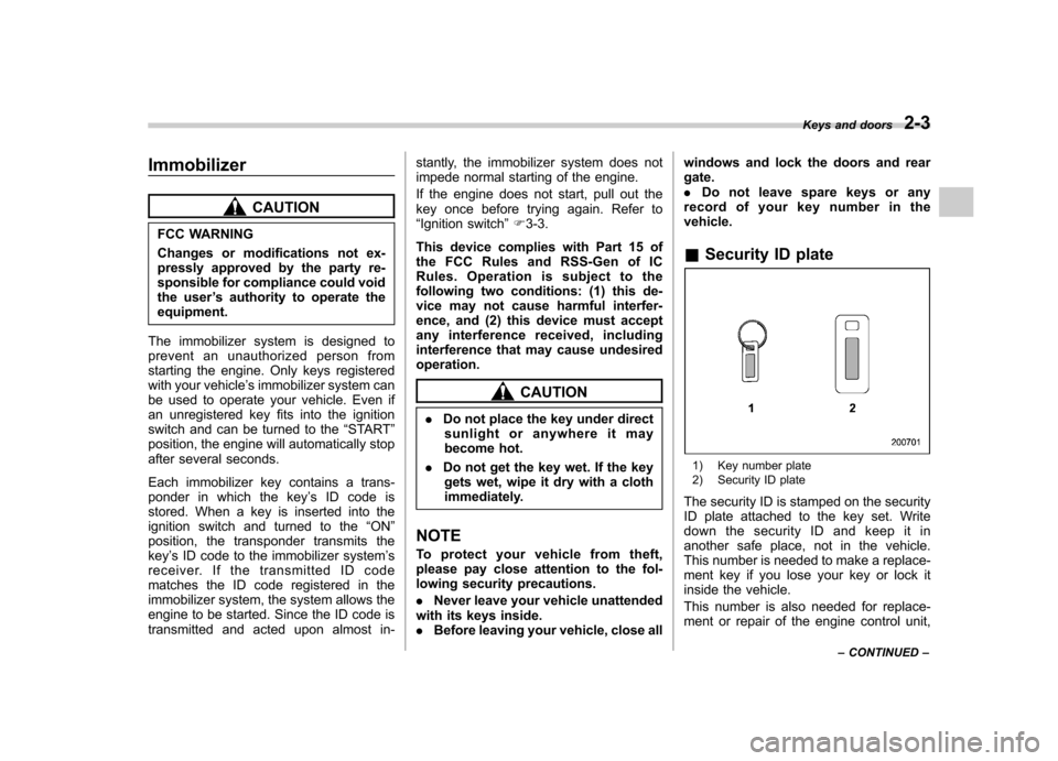
record of your key number in thevehicle. & Security ID plate
1) Key number plate
2) Security ID plate
The security ID is stamped on the security
ID plate attached to the key set. Write
down the security ID and keep it in
another safe place, not in the vehicle.
This number is needed to make a replace-
ment key if you lose your key or lock it
inside the vehicle.
This number is also needed for replace-
ment or repair of the engine control unit, Keys and doors
2-3
– CONTINUED –
Page 107 of 420

2-4Keys and doors
integrated unit, and combination meter. & Security indicator light
The security indicator light deters potential
thieves by indicating that the vehicle is
equipped with an immobilizer system. It
begins flashing approximately 60 seconds
after the ignition switch is turned from the“ON ”position to the “Acc ”or “LOCK ”
position or immediately after the key is
pulled out.
If the security indicator light does not flash,
the immobilizer system may be malfunc-
tioning. If this occurs, contact your
SUBARU dealer as soon as possible.
In case an unauthorized key is used (e.g.
an imitation key), the security indicator
light illuminates. NOTE
Even if the security indicator light
flashes irregularly or its fuse blows
(the light does not flash if its fuse is
blown), the immobilizer system will
function normally. &
Key replacement
Your key number plate and security ID
plate will be required if you ever need a
replacement key made. Any new key must
be registered for use with your vehicle ’s
immobilizer system before it can be used.
Up to four keys can be registered for use
with one vehicle.
For security, all the keys registered with
your vehicle ’s immobilizer system will
have their ID codes erased and re-
registered when a new key is made.
Therefore, all of your vehicle ’s keys must
be presented when a new key is regis-
tered. Any key that is not re-registered
when a new key is made cannot be used
after the other keys are re-registered. For
information on replacement keys and on
the registration of keys with your immo-
bilizer system, contact your SUBARU
dealer. NOTE
A vehicle that is equipped with the
remote engine start system as a dealer option can register up to three keys for
use with one vehicle.
Page 115 of 420
2-12Keys and doors
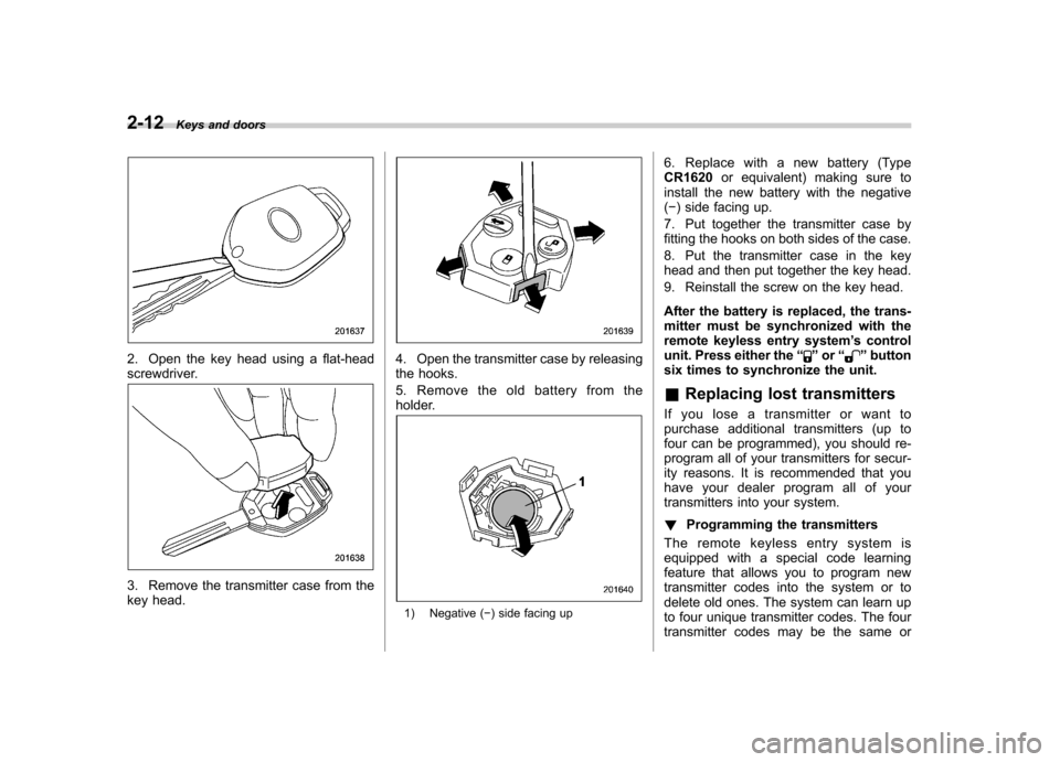
2. Open the key head using a flat-head
screwdriver.
3. Remove the transmitter case from the
key head.
4. Open the transmitter case by releasing
the hooks.
5. Remove the old battery from the
holder.
1) Negative ( �) side facing up 6. Replace with a new battery (Type CR1620
or equivalent) making sure to
install the new battery with the negative( � ) side facing up.
7. Put together the transmitter case by
fitting the hooks on both sides of the case.
8. Put the transmitter case in the key
head and then put together the key head.
9. Reinstall the screw on the key head.
After the battery is replaced, the trans-
mitter must be synchronized with the
remote keyless entry system ’s control
unit. Press either the “
”or “”button
six times to synchronize the unit. & Replacing lost transmitters
If you lose a transmitter or want to
purchase additional transmitters (up to
four can be programmed), you should re-
program all of your transmitters for secur-
ity reasons. It is recommended that you
have your dealer program all of your
transmitters into your system. ! Programming the transmitters
The remote keyless entry system is
equipped with a special code learning
feature that allows you to program new
transmitter codes into the system or to
delete old ones. The system can learn up
to four unique transmitter codes. The four
transmitter codes may be the same or