2012 SUBARU TRIBECA lock
[x] Cancel search: lockPage 225 of 420
6-6Interior equipment
Storage compartment
CAUTION
. Always keep the storage com-
partment closed while driving to
reduce the risk of injury in the
event of sudden stops or anaccident.
. Do not store spray cans, contain-
ers with flammable or corrosive
liquids or any other dangerous
items in the storage compart-ment. &
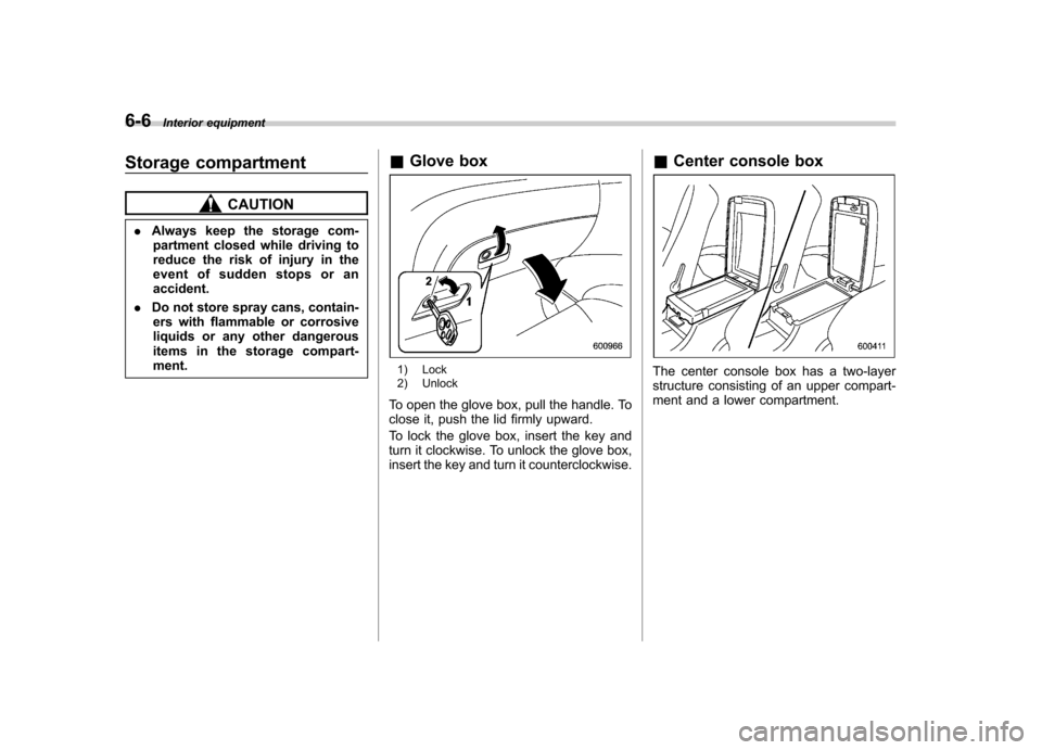
Glove box
1) Lock
2) Unlock
To open the glove box, pull the handle. To
close it, push the lid firmly upward.
To lock the glove box, insert the key and
turn it clockwise. To unlock the glove box,
insert the key and turn it counterclockwise. &
Center console boxThe center console box has a two-layer
structure consisting of an upper compart-
ment and a lower compartment.
Page 226 of 420
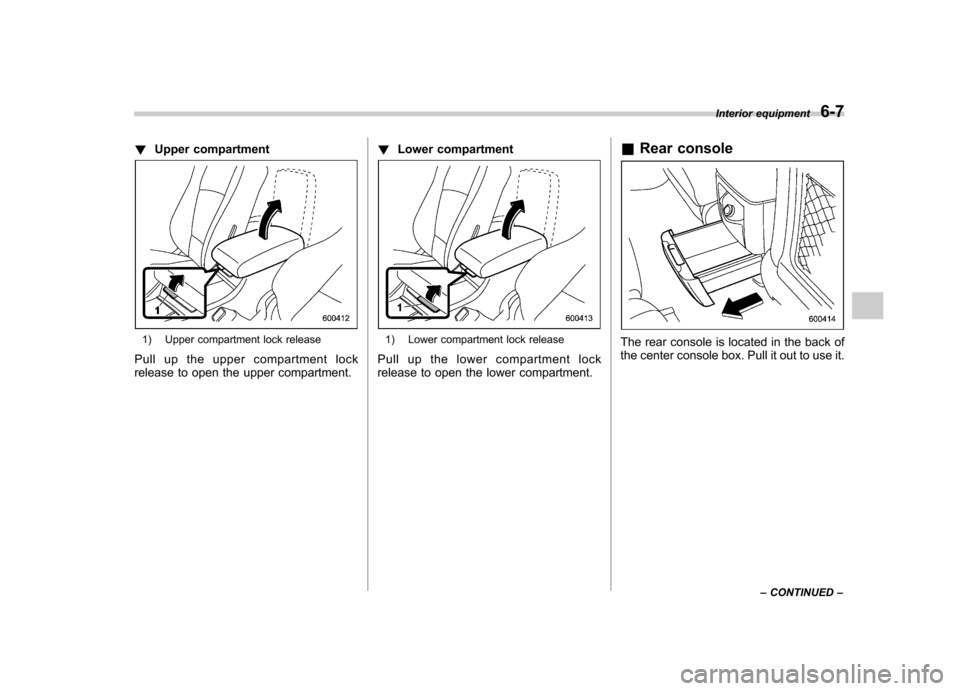
!Upper compartment
1) Upper compartment lock release
Pull up the upper compartment lock
release to open the upper compartment. !
Lower compartment1) Lower compartment lock release
Pull up the lower compartment lock
release to open the lower compartment. &
Rear consoleThe rear console is located in the back of
the center console box. Pull it out to use it. Interior equipment
6-7
– CONTINUED –
Page 234 of 420

CAUTION
. Be careful not to pinch your hand
between the headrest and the
cargo area cover when you re-
cline the second-row seat.
. Be careful not to scratch the rear
gate stays while extending and
rewinding the cover.
Scratches on the stays could
cause leakage of gas from the
stays, which may result in their
inability to hold the rear gateopen.
NOTE
When the head restraint is adjusted at
the rearmost position of the seat with
the seatback leaned back, the head
restraint comes in contact with the
cargo area cover. In this case, raise
the seatback before adjusting the headrestraint.
If the head restraint is correctly fixed in
any of the lock positions, the head
restraint does not contact the cargo
area cover even when the seatback isreclined. &
To remove the cover
1. Rewind the cover.
2. Pull either sleeve on the end of the
cover housing to shorten the cover ’s
length.
3. Take it off the retainer. &
To install the cover housing
1. Remove the cover at the cover hous-
ing retaining part using a flat-head screw-
driver.
2. Pull either sleeve on the end of the
cover housing to shorten the cover ’s
length. Interior equipment
6-15
– CONTINUED –
Page 236 of 420
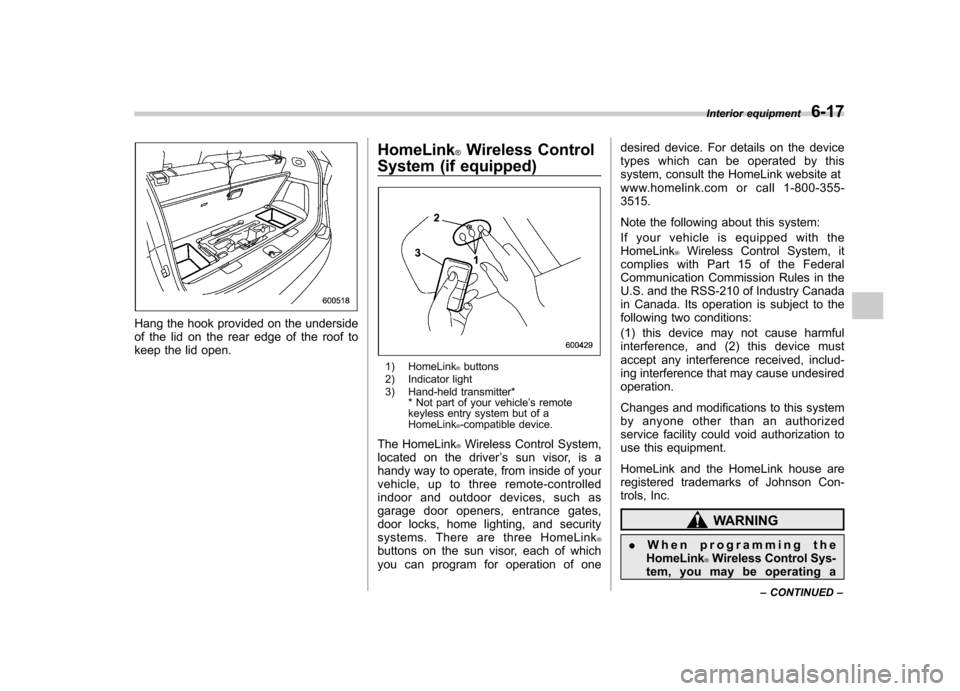
Hang the hook provided on the underside
of the lid on the rear edge of the roof to
keep the lid open.HomeLink
®Wireless Control
System (if equipped)
1) HomeLink®buttons
2) Indicator light
3) Hand-held transmitter* * Not part of your vehicle ’s remote
keyless entry system but of a HomeLink
®-compatible device.
The HomeLink
®Wireless Control System,
located on the driver ’s sun visor, is a
handy way to operate, from inside of your
vehicle, up to three remote-controlled
indoor and outdoor devices, such as
garage door openers, entrance gates,
door locks, home lighting, and security
systems. There are three HomeLink
®buttons on the sun visor, each of which
you can program for operation of one desired device. For details on the device
types which can be operated by this
system, consult the HomeLink website at
www.homelink.com or call 1-800-355-3515.
Note the following about this system:
If your vehicle is equipped with the HomeLink
®Wireless Control System, it
complies with Part 15 of the Federal
Communication Commission Rules in the
U.S. and the RSS-210 of Industry Canada
in Canada. Its operation is subject to the
following two conditions:
(1) this device may not cause harmful
interference, and (2) this device must
accept any interference received, includ-
ing interference that may cause undesiredoperation.
Changes and modifications to this system
by anyone other than an authorized
service facility could void authorization to
use this equipment.
HomeLink and the HomeLink house are
registered trademarks of Johnson Con-
trols, Inc.
WARNING
. When programming the
HomeLink
®Wireless Control Sys-
tem, you may be operating a Interior equipment
6-17
– CONTINUED –
Page 240 of 420
opener by pressing the programmed HomeLink®button.
& Programming other devices
To program other devices such as door
locks, home lighting and security systems,
contact HomeLink at www.homelink.com
or call 1-800-355-3515. & Operating the HomeLink
®
Wireless Control System
Once programmed, the HomeLink
®Wire-
less Control System can be used to
remote-control the devices to which its
buttons are programmed. To activate a
device, simply press the appropriate but-
ton. The indicator light illuminates, indicat-
ing that the signal is being transmitted.
& Erasing HomeLink
®button
memory
NOTE . Performing this procedure erases
the memory of all the preprogrammed
buttons simultaneously. The memory
of individual buttons cannot be erased. . It is recommended that upon the
sale of the vehicle, the memory of all
programmed HomeLink
®buttons be
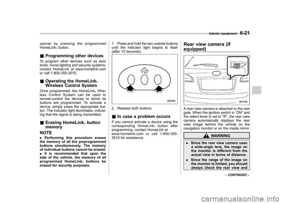
erased for security purposes. 1. Press and hold the two outside buttons
until the indicator light begins to flash
(after 10 seconds).
2. Release both buttons. &
In case a problem occurs
If you cannot activate a device using the
corresponding HomeLink
®button after
programming, contact HomeLink at
www.homelink.com or call 1-800-355-
3515 for assistance. Rear view camera (if
equipped)
A rear view camera is attached to the rear
gate. When the ignition switch is
“ON ”and
the select lever is set to “R ”, the rear view
camera automatically displays the rear
view image behind the vehicle on the
navigation monitor or on the inside mirror.
WARNING
. Since the rear view camera uses
a wide-angle lens, the image on
the monitor is different from the
actual view in terms of distance.
. Since the range of the image on
the monitor is limited, you should
always check the rear view and Interior equipment
6-21
– CONTINUED –
Page 246 of 420
Fuel...................................................................... 7-2
Fuel requirements ............................................... 7-2
Fuel filler lid and cap ........................................... 7-3
State emission testing (U.S. only) ...................... 7-5
Preparing to drive ............................................... 7-7
Starting the engine .............................................. 7-7
Stopping the engine ............................................ 7-8
Remote engine start system (dealer option) ..... 7-8
Starting your vehicle ........................................... 7-9
Remote start safety features ................................ 7-9
Entering the vehicle while it is running via remote start .................................................................. 7-9
Entering the vehicle following remote engine start shutdown .......................................................... 7-9
Pre-heating or pre-cooling the interior of the vehicle ............................................................. 7-10
Service mode ..................................................... 7-10
Remote engine start transmitter programming and programmable feature option ..................... 7-10
System maintenance .......................................... 7-11
Automatic transmission ..................................... 7-12
Select lever ........................................................ 7-13
Shift lock function .............................................. 7-14
Selection of manual mode .................................. 7-16
Driving tips ........................................................ 7-17
SPORT mode ..................................................... 7-18 Power steering
................................................... 7-18
Braking ............................................................... 7-19
Braking tips ....................................................... 7-19
Brake system .................................................... 7-19
Disc brake pad wear warning indicators ............. 7-20
ABS (Anti-lock Brake System) .......................... 7-20
ABS system self-check ...................................... 7-21
ABS warning light .............................................. 7-21
Electronic Brake Force Distribution (EBD) system ............................................................. 7-22
Steps to take if EBD system malfunctions ..... ..... 7-22
Vehicle Dynamics Control system .................... 7-23
Vehicle Dynamics Control system monitor..... ..... 7-25
Traction Control system OFF switch ................... 7-25
Tire pressure monitoring system (TPMS) ........ 7-27
Parking your vehicle ......................................... 7-28
Parking brake .................................................... 7-28
Parking tips ....................................................... 7-29
Cruise control .................................................... 7-29
To set cruise control .......................................... 7-30
To temporarily cancel the cruise control ............. 7-30
To turn off the cruise control .............................. 7-31
To change the cruising speed .. .......................... 7-31
Cruise control indicator light .............................. 7-32
Cruise control set indicator light ........................ 7-32
Starting and operating
7
Page 249 of 420
7-4Starting and operating
WARNING
Before opening the fuel filler cap,
first touch the vehicle body or a
metal portion of the fuel pump or
similar object to discharge any
static electricity that may be present
on your body. If your body is carry-
ing an electrostatic charge, there is
a possibility that an electric spark
could ignite the fuel, which could
burn you. To avoid acquiring a new
static electric charge, do not get
back into the vehicle while refueling
is in progress.
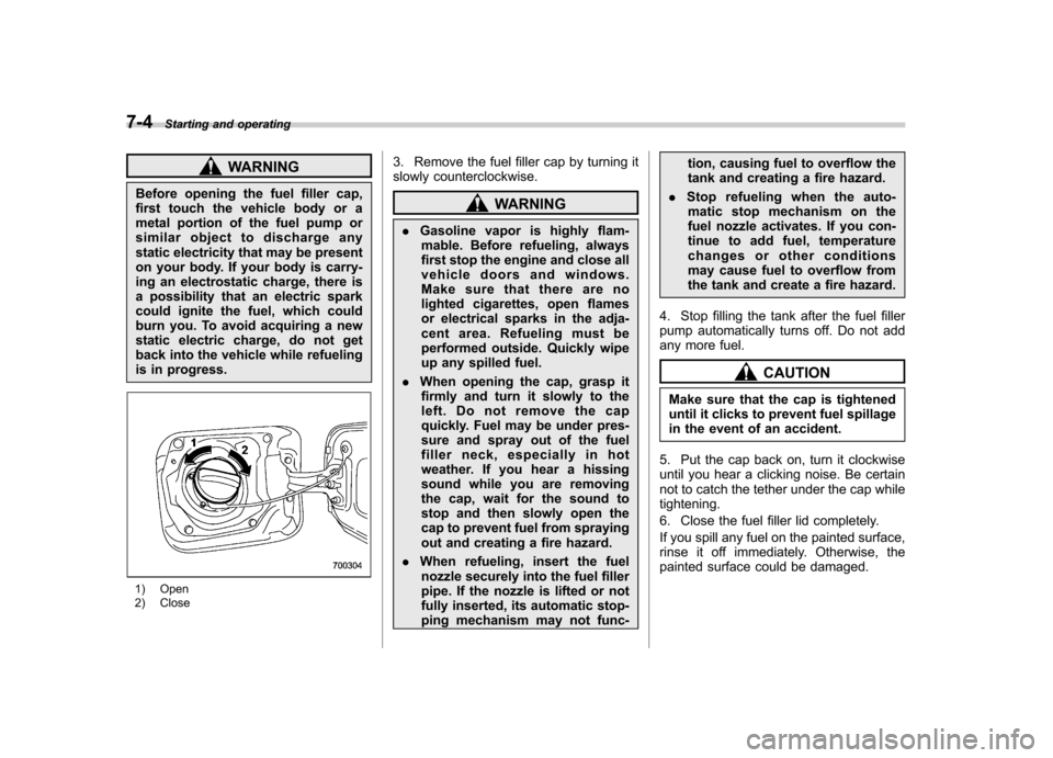
1) Open
2) Close 3. Remove the fuel filler cap by turning it
slowly counterclockwise.
WARNING
. Gasoline vapor is highly flam-
mable. Before refueling, always
first stop the engine and close all
vehicle doors and windows.
Make sure that there are no
lighted cigarettes, open flames
or electrical sparks in the adja-
cent area. Refueling must be
performed outside. Quickly wipe
up any spilled fuel.
. When opening the cap, grasp it
firmly and turn it slowly to the
left. Do not remove the cap
quickly. Fuel may be under pres-
sure and spray out of the fuel
filler neck, especially in hot
weather. If you hear a hissing
sound while you are removing
the cap, wait for the sound to
stop and then slowly open the
cap to prevent fuel from spraying
out and creating a fire hazard.
. When refueling, insert the fuel
nozzle securely into the fuel filler
pipe. If the nozzle is lifted or not
fully inserted, its automatic stop-
ping mechanism may not func- tion, causing fuel to overflow the
tank and creating a fire hazard.
. Stop refueling when the auto-
matic stop mechanism on the
fuel nozzle activates. If you con-
tinue to add fuel, temperature
changes or other conditions
may cause fuel to overflow from
the tank and create a fire hazard.
4. Stop filling the tank after the fuel filler
pump automatically turns off. Do not add
any more fuel.
CAUTION
Make sure that the cap is tightened
until it clicks to prevent fuel spillage
in the event of an accident.
5. Put the cap back on, turn it clockwise
until you hear a clicking noise. Be certain
not to catch the tether under the cap whiletightening.
6. Close the fuel filler lid completely.
If you spill any fuel on the painted surface,
rinse it off immediately. Otherwise, the
painted surface could be damaged.
Page 252 of 420
Preparing to drive
You should perform the following checks
and adjustments every day before you
start driving.
1. Check that all windows, mirrors, and
lights are clean and unobstructed.
2. Check the appearance and condition
of the tires. Also check tires for properinflation.
3. Look under the vehicle for any sign of leaks.
4. Check that the hood and rear gate are
fully closed.
5. Check the adjustment of the seat.
6. Check the adjustment of the inside
and outside mirrors.
7. Fasten your seatbelt. Check that your
passengers have fastened their seatbelts.
8. Check the operation of the warning
and indicator lights when the ignition
switch is turned to the“ON ”position.
9. Check the gauges, indicator and warn-
ing lights after starting the engine.
NOTE
Engine oil, engine coolant, brake fluid,
washer fluid and other fluid levels
should be checked daily, weekly or at
fuel stops. Starting the engine
CAUTION
. Do not operate the starter motor
continuously for more than 10
seconds. If the engine fails to
start after operating the starter
for 5 to 10 seconds, wait for 10
seconds or more before tryingagain.
. If you restart the engine while the
vehicle is moving, shift the select
lever into the “N ” position. Do
not attempt to place the select
lever of a moving vehicle into the“ P ” position.
1. Apply the parking brake.
2. Turn off unnecessary lights and ac- cessories.
3. Shift the select lever to the “P ” or “N ”
position (preferably “P ” position). The
starter will only operate when the select
lever is at the “P ”or “N ”position.
4. Turn the ignition switch to the “ON ”
position and check the operation of the
warning and indicator lights. Refer to“ Warning and indicator lights ”F 3-9.
5. Turn the ignition switch to the “START ”
position without depressing the accelera- tor pedal. Release the key immediately
after the engine has started.
If the engine does not start, try the following.
(1) Turn the ignition switch to the“LOCK ”position and wait for at least
10 seconds. After checking that the
parking brake is firmly set, turn the
ignition switch to the “START ”position
while depressing the accelerator pedal
slightly (approximately a quarter of the
full stroke). Release the accelerator
pedal as soon as the engine starts.
(2) If this fails to start the engine, turn
the ignition switch back to the “LOCK ”
position and wait for at least 10
seconds. Then fully depress the accel-
erator pedal and turn the ignition
switch to the “START ”position. If the
engine starts, quickly release the
accelerator pedal.
(3) If this fails to start the engine, turn
the ignition switch again to the “LOCK ”
position. After waiting for 10 seconds
or longer, turn the ignition switch to the“ START ”position without depressing
the accelerator pedal.
(4) If the engine still refuses to start,
contact your nearest SUBARU dealer
for assistance.
6. Confirm that all warning and indicator
lights have turned off after the engine has Starting and operating
7-7
– CONTINUED –