2012 SUBARU OUTBACK engine
[x] Cancel search: enginePage 92 of 474

Immobilizer
The immobilizer system is designed to
prevent an unauthorized person from
starting the engine. Only keys registered
with your vehicle’s immobilizer system can
be used to operate your vehicle. Even if
an unregistered key fits into the ignition
switch and can be turned to the “START ”
position, the engine will automatically stop
after several seconds.
Each immobilizer key contains a trans-
ponder in which the key ’s ID code is
stored. When a key is inserted into the
ignition switch and turned to the “ON ”
position, the transponder transmits thekey ’s ID code to the immobilizer system ’s
receiver. If the transmitted ID code
matches the ID code registered in the
immobilizer system, the system allows the
engine to be started. Since the ID code is
transmitted and acted upon almost in-
stantly, the immobilizer system does not
impede normal starting of the engine.
If the engine does not start, pull out the
key once before trying again. Refer to“ Ignition switch ”F 3-3.
This device complies with Part 15 of
the FCC Rules and RSS-Gen of IC
Rules. Operation is subject to the
following two conditions: (1) This de- vice may not cause harmful interfer-
ence, and (2) this device must accept
any interference received, including
interference that may cause undesiredoperation.
CAUTION
. Do not place the key under direct
sunlight or anywhere it may
become hot.
. Do not get the key wet. If the key
gets wet, wipe it dry with a cloth
immediately.
. FCC WARNING
Changes or modifications not
expressly approved by the party
responsible for compliance
could void the user ’s authority
to operate the equipment.
NOTE
To protect your vehicle from theft,
please pay close attention to the fol-
lowing security precautions: . Never leave your vehicle unattended
with its keys inside. . Before leaving your vehicle, close all
windows and the moonroof, and lock
the doors (all models) and rear gate(Outback). .
Do not leave spare keys or any
record of your key number in thevehicle. & Security ID plate
1) Key number plate
2) Security ID plate
The security ID is stamped on the security
ID plate attached to the key set. Write
down the security ID and keep it in
another safe place, not in the vehicle.
This number is needed to make a replace-
ment key if you lose your key or lock it
inside the vehicle.
To make replacement keys, the key
number is also needed. Refer to “Key
replacement ”F 2-4. Keys and doors
2-3
– CONTINUED –
Page 93 of 474
2-4Keys and doors
The security ID is also needed for
replacement or repair of the engine control
unit, integrated unit, etc. For details,
consult your SUBARU dealer. &Security indicator light
Refer to “Security indicator light ”F 3-21.
& Key replacement
Your key number plate and security ID
plate will be required if you ever need a
replacement key made. Any new key must
be registered for use with your vehicle ’s
immobilizer system before it can be used.
Up to four keys can be registered for use
with one vehicle.
For security, all the keys registered with
your vehicle ’s immobilizer system will
have their ID codes erased and re-
registered when a new key is made.
Therefore, all of your vehicle ’s keys must
be presented when a new key is regis-
tered. Any key that is not re-registered
when a new key is made cannot be used
after the other keys are re-registered. For
information on replacement keys and on
the registration of keys with your immo-
bilizer system, contact your SUBARU
dealer. Door locks &
Locking and unlocking from
the outside
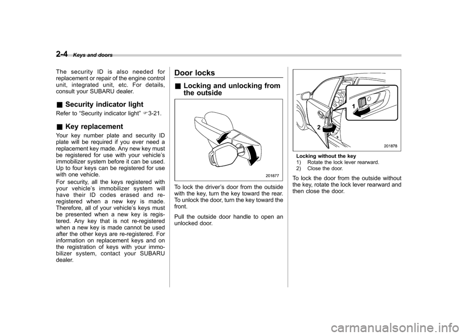
To lock the driver ’s door from the outside
with the key, turn the key toward the rear.
To unlock the door, turn the key toward thefront.
Pull the outside door handle to open an
unlocked door.
Locking without the key
1) Rotate the lock lever rearward.
2) Close the door.
To lock the door from the outside without
the key, rotate the lock lever rearward and
then close the door.
Page 105 of 474
2-16Keys and doors
1 second, and wait 10 seconds without
releasing the switch. The setting will then
be changed as follows:
If the system was previously activated:
The trip meter screen displays “AL oF ”
and the horn sounds twice, indicating that
the system is now deactivated.
If the system was previously deacti- vated:
The trip meter screen displays “AL on ”and
the horn sounds once, indicating that the
system is now activated.
NOTE
You may have the above setting
change done by your SUBARU dealer. & If you have accidentally trig-
gered the alarm system
! To stop the alarm
Perform any of the following operations. . Press any button on the remote trans-
mitter.. Turn the ignition switch to the “ON ”
position. &
Arming the system
! To arm the system using remote transmitter
1. Close all windows and the moonroof (ifequipped).
2. Remove the key from the ignition switch.
3. Open the doors and get out of the vehicle.
4. Make sure that the engine hood (and
the trunk lid (Legacy)) are locked.
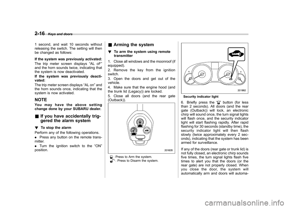
5. Close all doors (and the rear gate (Outback)).
: Press to Arm the system.: Press to Disarm the system.
Security indicator light
6. Briefly press the “
”button (for less
than 2 seconds). All doors (and the rear
gate (Outback)) will lock, an electronic
chirp will sound once, the turn signal lights
will flash once, and the security indicator
light will start flashing rapidly. After rapid
flashing for 30 seconds (standby time), the
security indicator l ight will then flash
slowly (twice approximately every 2 sec-
onds), indicating that the system has been
armed for surveillance.
If any of the doors (rear gate or trunk lid) is
not fully closed, an electronic chirp sounds
five times, the turn signal lights flash five
times to alert you that the doors (or the
rear gate) are not properly closed. When
you close the door, the system will
automatically arm and doors will automa-
Page 106 of 474

tically lock. !To arm the system using power
door locking switch
1. Close all windows.
2. Remove the key from the ignition switch.
3. Open the doors and get out of the vehicle.
4. Make sure that the engine hood is locked.
5. Close the doors (and the rear gate
(Outback)) but leave only the driver ’s door
or the front passenger ’s door open.
6. Press the front side ( “LOCK ”side) of
the power door locking switch to set the
door locks.
7. Close the door. An electronic chirp will
sound once, the turn signal lights will flash once and the security indicator light will
start flashing rapidly. After rapid flashing
for 30 seconds (standby time), the security
indicator light will then flash slowly (twice
approximately every 2 seconds), indicat-
ing that the system has been armed forsurveillance.
NOTE . The system can be armed even if the
engine hood, the windows and/or
moonroof are open. Always make sure
that they are fully closed before arming
the system.. The 30-second standby time can be
eliminated if you prefer. Have it per-
formed by your SUBARU dealer.. If your vehicle is a Legacy and you
open the trunk using the remote trans-mitter ’s “
”button with the alarm
system armed, the system will be
temporarily placed in a standby state.
The system will go back to the surveil-
lance state upon locking the trunk.. The system is in the standby mode
for a 30-second period after locking the
doors with the remote transmitter. The
security indicator light will flash at
short intervals during this period.. If any of the following actions is
done during the standby period, the
system will not switch to the surveil- lance state.
–Doors are unlocked using the
remote transmitter. – Any door (including the rear gate
(Outback) or the trunk (Legacy)) is opened. – Ignition switch is turned to the
“ ON ”position.
& Disarming the system
Briefly press the “
”button (for less than
2 seconds) on the remote transmitter. The
driver ’s door will unlock, an electronic
chirp will sound twice, the turn signal
lights will flash twice and the security
indicator light will turn off.
To unlock all other doors and the rear gate
(Outback), briefly press the “
”button a
second time within 5 seconds. ! Emergency disarming
If you cannot disarm the system using the
transmitter (i.e. the transmitter is lost,
broken or the transmitter battery is too
weak), you can disarm the system without
using the transmitter.
The system can be disarmed if you turn
the ignition switch from the “LOCK ”to the
“ ON ”position with a registered key. Keys and doors
2-17
– CONTINUED –
Page 120 of 474

Ignition switch..................................................... 3-3
LOCK .................................................................. 3-3
Acc..................................................................... 3-4
ON...................................................................... 3-4
START ................................................................ 3-4
Key reminder chime ............................................ 3-4
Ignition switch light ............................................. 3-4
Hazard warning flasher ....................................... 3-5
Meters and gauges. ............................................. 3-5
Combination meter illumination ........................... 3-5
Canceling the function for meter/gauge needle movement upon turning on the ignition switch ............................................................... 3-5
Speedometer ....................................................... 3-6
Odometer ............................................................ 3-6
Double trip meter ................................................ 3-6
Tachometer ......................................................... 3-7
Fuel gauge .......................................................... 3-7
ECO gauge ......................................................... 3-8
Warning and indicator lights .............................. 3-9
Seatbelt warning light and chime ......................... 3-9
SRS airbag system warning light ........................ 3-11
Front passenger ’s frontal airbag ON and OFF
indicators ......................................................... 3-11
CHECK ENGINE warning light/Malfunction indicator light ................................................... 3-12
Coolant temperature low indicator light/Coolant temperature high warning light ......................... 3-13
Charge warning light .......................................... 3-14
Oil pressure warning light .................................. 3-14
Engine low oil level warning light ....................... 3-14AT OIL TEMP warning light (AT and CVT
models) ........................................................... 3-14
Low tire pressure warning light (U.S. spec. models) ........................................................... 3-15
ABS warning light .............................................. 3-16
Brake system warning light ................................ 3-17
Hill Holder indicator light ................................... 3-19
Low fuel warning light ....................................... 3-19
Door open indicator light ................................... 3-19
Windshield washer fluid warning light ................ 3-19
All-Wheel Drive warning light (AT and CVT models) ........................................................... 3-20
Vehicle Dynamics Control warning light/Vehicle Dynamics Control operation indicator light .. ..... 3-20
Vehicle Dynamics Control OFF indicator light ..... 3-21
Security indicator light ....................................... 3-21
Select lever/gear position indicator ..................... 3-22
Turn signal indicator lights ................................. 3-22
High beam indicator light ................................... 3-22
Cruise control indicator light .............................. 3-23
Cruise control set indicator light ........................ 3-23
Headlight indicator light ..................................... 3-23
Front fog light indicator light (if equipped) ..... ..... 3-23
Clock .................................................................. 3-23
Multi function display ........................................ 3-24
Outside temperature indicator .. .......................... 3-24
Average fuel consumption ................................. 3-25
Current fuel consumption .................................. 3-26
Driving range on remaining fuel ......................... 3-26
Light control switch ........................................... 3-27
Headlights ......................................................... 3-27
Instruments and controls
3
Page 122 of 474
Ignition switch
WARNING
. Never turn the ignition switch to
“ LOCK ”while the vehicle is
being driven or towed because
that will lock the steering wheel,
preventing steering control. And
when the engine is turned off, it
takes a much greater effort than
usual to steer.
. Before leaving the vehicle, al-
ways remove the key from the
ignition switch for safety and
never allow an unattended child
to remain in the vehicle. Failure
to follow this procedure could
result in injury to a child or
others. Children could operate
the power windows, the moon-
roof or other controls or even
make the vehicle move.
CAUTION
Do not attach a large key holder or
key case to either key. If it banged
against your knees or hands while
you are driving, it could turn the
ignition switch from the “ON ”posi- tion to the
“Acc ”or “LOCK ”posi-
tion, thereby stopping the engine.
Also, if the key is attached to a
keyholder or to a large bunch of
other keys, centrifugal force may act
on it as the vehicle moves, resulting
in unwanted turning of the ignitionswitch.
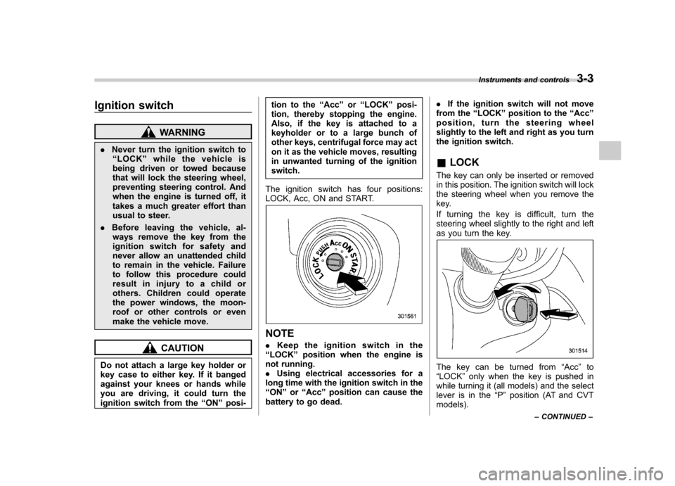
The ignition switch has four positions:
LOCK, Acc, ON and START.
NOTE . Keep the ignition switch in the
“ LOCK ”position when the engine is
not running. . Using electrical accessories for a
long time with the ignition switch in the“ ON ”or “Acc ”position can cause the
battery to go dead. .
If the ignition switch will not move
from the “LOCK ”position to the “Acc ”
position, turn the steering wheel
slightly to the left and right as you turn
the ignition switch. & LOCK
The key can only be inserted or removed
in this position. The ignition switch will lock
the steering wheel when you remove the
key.
If turning the key is difficult, turn the
steering wheel slightly to the right and left
as you turn the key.
The key can be turned from “Acc ”to
“ LOCK ”only when the key is pushed in
while turning it (all models) and the select
lever is in the “P ” position (AT and CVT
models). Instruments and controls
3-3
– CONTINUED –
Page 123 of 474
3-4Instruments and controls
&Acc
In this position the electrical accessories
(radio, accessory power outlet, etc.) can
be used. & ON
This is the normal operating position after
the engine is started. & START
CAUTION
Do not turn the ignition switch to the “ START ”position while the engine
is running.
The engine is started in this position. The
starter cranks the engine to start it. When
the key is released (after the engine has
started), the key automatically returns tothe “ON ”position.
If the engine does not start with your
registered key, pull out the key once (at
this time, the security indicator light will
blink), wait for at least 10 seconds,
reinsert the key in the ignition switch and
then try to start the engine again.
NOTE
The engine may not start in the follow-
ing cases:
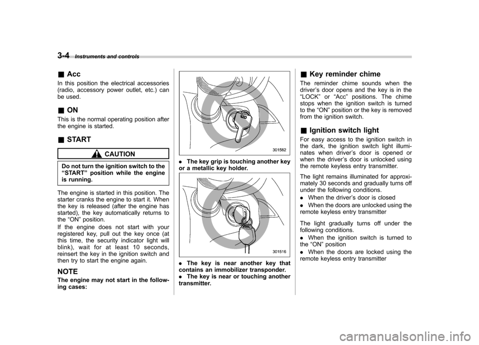
. The key grip is touching another key
or a metallic key holder.
. The key is near another key that
contains an immobilizer transponder. . The key is near or touching another
transmitter. &
Key reminder chime
The reminder chime sounds when thedriver ’s door opens and the key is in the
“ LOCK ”or “Acc ”positions. The chime
stops when the ignition switch is turned
to the “ON ”position or the key is removed
from the ignition switch.
& Ignition switch light
For easy access to the ignition switch in
the dark, the ignition switch light illumi-
nates when driver ’s door is opened or
when the driver ’s door is unlocked using
the remote keyless entry transmitter.
The light remains illuminated for approxi-
mately 30 seconds and gradually turns off
under the following conditions. . When the driver ’s door is closed
. When the doors are unlocked using the
remote keyless entry transmitter
The light gradually turns off under the
following conditions. . When the ignition switch is turned to
the “ON ”position
. When the doors are locked using the
remote keyless entry transmitter
Page 124 of 474
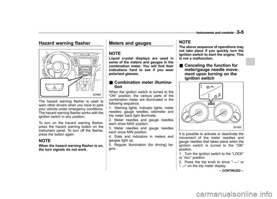
Hazard warning flasher
The hazard warning flasher is used to
warn other drivers when you have to park
your vehicle under emergency conditions.
The hazard warning flasher works with the
ignition switch in any position.
To turn on the hazard warning flasher,
press the hazard warning button on the
instrument panel. To turn off the flasher,
press the button again. NOTE
When the hazard warning flasher is on,
the turn signals do not work.Meters and gauges NOTE
Liquid crystal displays are used in
some of the meters and gauges in the
combination meter. You will find their
indications hard to see if you wear
polarized glasses. &
Combination meter illumina- tion
When the ignition switch is turned to the “ ON ”position, the various parts of the
combination meter are illuminated in the
following sequence.
1. Warning lights, indicator lights, meter
needles, gauge needles, odometer and
trip meter back light illuminate.
2. Meter needles and gauge needles
each show MAX position.
3. Meter needles and gauge needles
each show MIN position.
4. Dials and indicators in meters and
gauges light up.
5. Regular illumination (for driving) be- gins. NOTE
The above sequence of operations may
not take place if you quickly turn the
ignition switch to start the engine. This
is not a malfunction. &
Canceling the function for
meter/gauge needle move-
ment upon turning on the
ignition switch
It is possible to activate or deactivate the
movement of the meter needles and
gauge needles that takes place when the
ignition switch is turned to the “ON ”
position.
1. Turn the ignition switch to the “LOCK ”
or “Acc ”position.
2. Press the trip knob to show “
”or
“” on the trip meter display. Instruments and controls
3-5
– CONTINUED –