2012 SUBARU IMPREZA WRX coolant temperature
[x] Cancel search: coolant temperaturePage 127 of 416
3-10Instruments and controls
&Temperature gauge
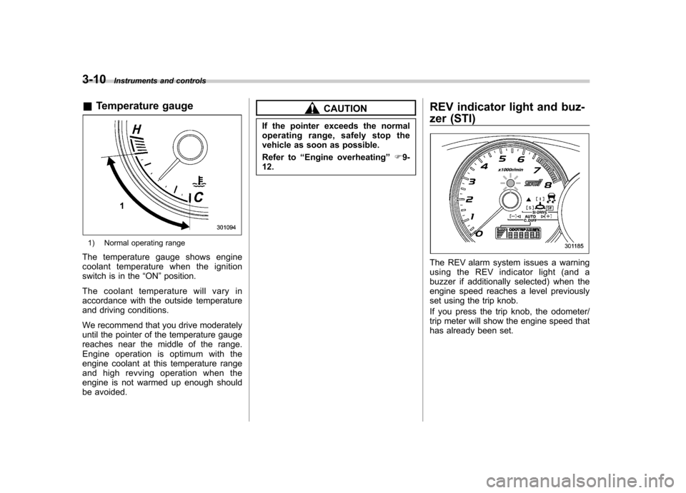
1) Normal operating range
The temperature gauge shows engine
coolant temperature when the ignition
switch is in the “ON ”position.
The coolant temperature will vary in
accordance with the outside temperature
and driving conditions.
We recommend that you drive moderately
until the pointer of the temperature gauge
reaches near the middle of the range.
Engine operation is optimum with the
engine coolant at this temperature range
and high revving operation when the
engine is not warmed up enough should
be avoided.
CAUTION
If the pointer exceeds the normal
operating range, safely stop the
vehicle as soon as possible.
Refer to “Engine overheating ”F9-
12. REV indicator light and buz-
zer (STI)
The REV alarm system issues a warning
using the REV indicator light (and a
buzzer if additionally selected) when the
engine speed reaches a level previously
set using the trip knob.
If you press the trip knob, the odometer/
trip meter will show the engine speed that
has already been set.
Page 173 of 416
4-8Climate control
Automatic climate control
system (if equipped)
Although this climate control system can
be used as a full-automatic climate control
system, it can also, if desired, be used as
a semi-automatic climate control system.
When it is used as a full-automatic climate
control system, the outlet air temperature,
fan speed, airflow distribution, air inlet
control, and air conditioner compressor
operation are all automatically controlled
to maintain a constant, comfortable tem-
perature inside the vehicle. NOTE .Operate the automatic climate con-
trol system when the engine is running. . When the engine coolant is cold, the
blower does not run.. In the “AUTO ”mode, when the air
temperature in the passenger compart-
ment is sufficiently cool, the air condi-
tioner compressor does not operate.
For efficient defogging or dehumidify-
ing in cold weather, press the “A/C ”
button to operate the air conditioner
compressor. &
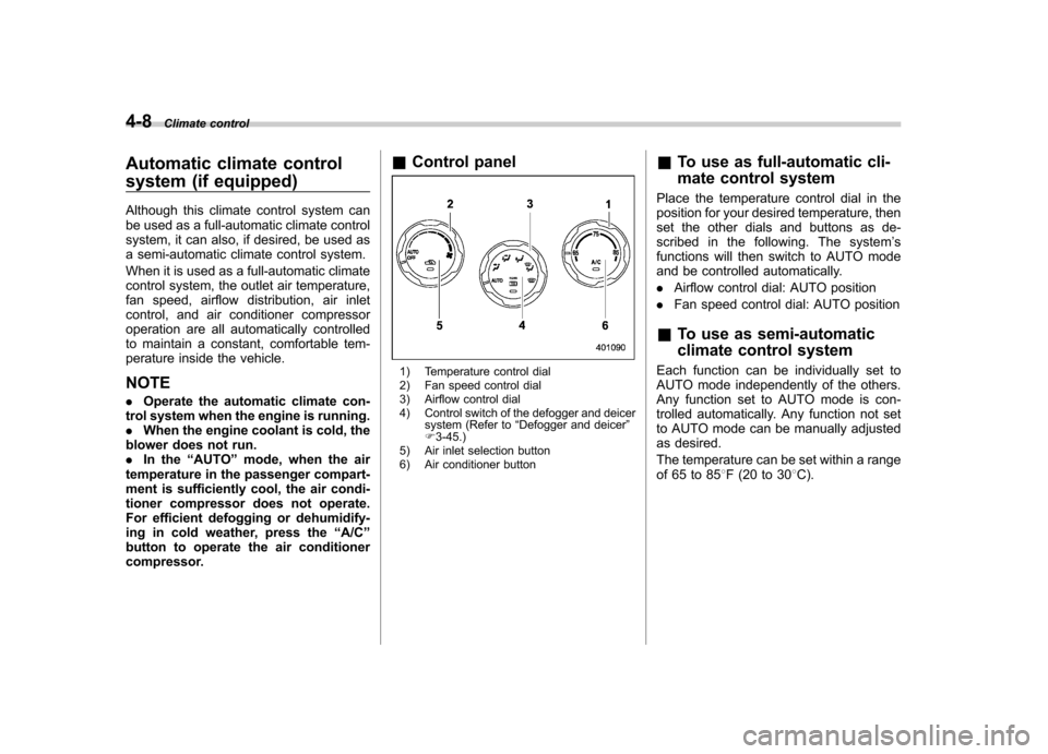
Control panel
1) Temperature control dial
2) Fan speed control dial
3) Airflow control dial
4) Control switch of the defogger and deicer
system (Refer to “Defogger and deicer ”
F 3-45.)
5) Air inlet selection button
6) Air conditioner button &
To use as full-automatic cli-
mate control system
Place the temperature control dial in the
position for your desired temperature, then
set the other dials and buttons as de-
scribed in the following. The system ’s
functions will then switch to AUTO mode
and be controlled automatically. . Airflow control dial: AUTO position
. Fan speed control dial: AUTO position
& To use as semi-automatic
climate control system
Each function can be individually set to
AUTO mode independently of the others.
Any function set to AUTO mode is con-
trolled automatically. Any function not set
to AUTO mode can be manually adjusted
as desired.
The temperature can be set within a range
of 65 to 85 8F (20 to 30 8C).
Page 174 of 416

&Fan speed control dial
The fan operates only with the ignition
switch in the ON position. The fan speed
control dial is used to select the AUTO
(automatic control) mode or to select the
desired fan speed. The dial ’s positions
and their functions are as follows. OFF: The fan does not operate.
AUTO: The fan speed is adjusted auto-
maticallyinaccordancewiththeair
temperature inside and outside the pas-
senger compartment, the intensity of sun-
light, and other factors. SUBARU recom-
mends using the AUTO position.
Other positions: The fan speed can be
adjusted in 7 steps. NOTE
With the fan speed control dial in the
AUTO position and the airflow control
dial in the
“
”, “”,or “”position,
the fan does not operate during engine
warm-up until the engine coolant tem-
perature exceeds approximately 122 8F
(50 8C).
& Temperature control dial
This dial is used to set the desired interior
temperature. With the dial set to your
desired temperature, the system automa-
tically adjusts the temperature of air
supplied from the outlets such that the
desired temperature is achieved andmaintained.
If the dial is turned fully counterclockwise, the system gives maximum cooling per-
formance. If the dial is turned fully clock-
wise, the system gives maximum heatingperformance. &
Airflow control dial
Each dial position activates the following
air outlets. AUTO: The airflow control is adjusted
automatically in accordance with the air
temperature inside and outside the pas-
senger compartment, the intensity of sun-
light, and other factors. SUBARU recom-
mends using the AUTO position.
(Ventilation): Instrument panel outlets
(Bi-level): Instrument panel outlets and
foot outlets
(Heat): Foot outlets, both side outlets of Climate control
4-9
– CONTINUED –
Page 266 of 416
&Sport Sharp (S#) mode
! For maximum performance driving
For sports-minded drivers, the Sport
Sharp (S#) mode offers an exhilarating
level of engine performance and control.
The throttle becomes more responsive
regardless of the engine speed. Delivering
maximum driving enjoyment, this mode is
ideal for tackling twisting roads and for
merging or overtaking other vehicles on
the freeway with confidence. &
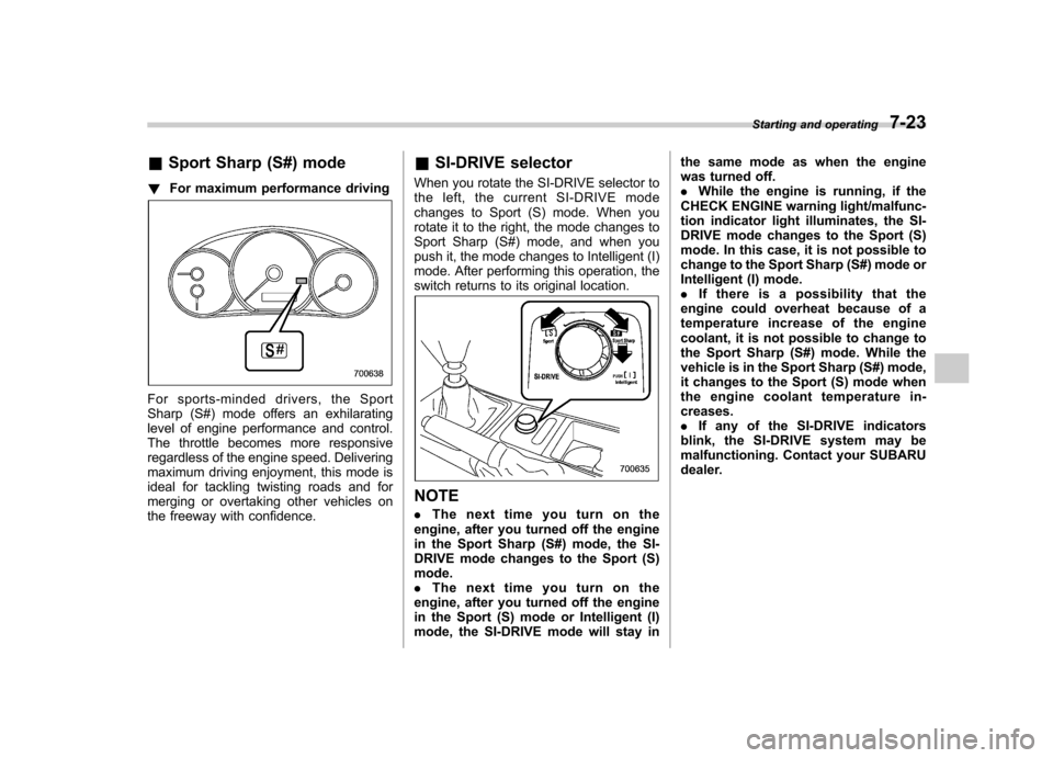
SI-DRIVE selector
When you rotate the SI-DRIVE selector to
the left, the current SI-DRIVE mode
changes to Sport (S) mode. When you
rotate it to the right, the mode changes to
Sport Sharp (S#) mode, and when you
push it, the mode changes to Intelligent (I)
mode. After performing this operation, the
switch returns to its original location.
NOTE . The next time you turn on the
engine, after you turned off the engine
in the Sport Sharp (S#) mode, the SI-
DRIVE mode changes to the Sport (S)mode.. The next time you turn on the
engine, after you turned off the engine
in the Sport (S) mode or Intelligent (I)
mode, the SI-DRIVE mode will stay in the same mode as when the engine
was turned off..
While the engine is running, if the
CHECK ENGINE warning light/malfunc-
tion indicator light illuminates, the SI-
DRIVE mode changes to the Sport (S)
mode. In this case, it is not possible to
change to the Sport Sharp (S#) mode or
Intelligent (I) mode.. If there is a possibility that the
engine could overheat because of a
temperature increase of the engine
coolant, it is not possible to change to
the Sport Sharp (S#) mode. While the
vehicle is in the Sport Sharp (S#) mode,
it changes to the Sport (S) mode when
the engine coolant temperature in- creases.. If any of the SI-DRIVE indicators
blink, the SI-DRIVE system may be
malfunctioning. Contact your SUBARU
dealer. Starting and operating
7-23
Page 309 of 416
9-12In case of emergency
Engine overheating
WARNING
Never attempt to remove the radia-
tor cap until the engine has been
shut off and has fully cooled down.
When the engine is hot, the coolant
is under pressure. Removing the
cap while the engine is still hot
could release a spray of boiling hot
coolant, which could burn you very
seriously.
If the engine overheats, safely pull off the
road and stop the vehicle in a safe place. & If steam is coming from the
engine compartment
Turn off the engine and get everyone
away from the vehicle until it cools down. & If no steam is coming from
the engine compartment
NOTE
For details about how to check the
coolant level or how to add coolant,
refer to “Engine coolant ”F 11-12.
1. Keep the engine running at idlingspeed. 2. Open the hood to ventilate the engine
compartment. Refer to
“Engine hood ”
F 11-5.
Confirm that the cooling fan is turning. If
the fan is not turning, immediately turn off
the engine and contact your authorized
dealer for repair.
3. After the engine coolant temperature
has dropped, turn off the engine.
If temperature gauge stays in the over-
heated zone, turn off the engine. Refer to“ Temperature gauge ”F 3-10.
4. After the engine has fully cooled down,
check the coolant level in the reservetank.
If the coolant level is below the “LOW ”
mark, add coolant up to the “FULL ”mark.
5. If there is no coolant in the reserve
tank, add coolant to the reserve tank.
Then remove the radiator cap and fill the
radiator with coolant.
If you remove the radiator cap from a hot
radiator, first wrap a thick cloth around the
radiator cap, then turn the cap counter-
clockwise slowly without pressing down
until it stops. Release the pressure from
the radiator. After the pressure has been
fully released, remove the cap by pressing
down and turning it. Towing
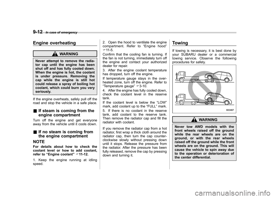
If towing is necessary, it is best done by
your SUBARU dealer or a commercial
towing service. Observe the following
procedures for safety.
WARNING
Never tow AWD models with the
front wheels raised off the ground
while the rear wheels are on the
ground, or with the rear wheels
raised off the ground while the front
wheels are on the ground. This will
cause the vehicle to spin away due
to the operation or deterioration of
the center differential.
Page 332 of 416
mended engine oil for optimum engine
performance. Conventional oil may be
used if synthetic oil is unavailable.Cooling system
WARNING
Never attempt to remove the radia-
tor cap until the engine has been
shut off and has cooled down
completely. Since the coolant is
under pressure, you may suffer
serious burns from a spray of boil-
ing hot coolant when the cap isremoved.
CAUTION
. Vehicles are filled at the factory
with SUBARU Super Coolant that
does not require the first change
for 11 years/137,500 miles (11
years/220,000 km). This coolant
should not be mixed with any
other brand or type of coolant
during this period. Mixing with a
different coolant will reduce the
life of the coolant. Should it be
necessary to top up the coolant
for any reason, use only
SUBARU Super Coolant.
If the SUBARU Super Coolant is
diluted with another brand or
type, the maintenance interval is shortened to that of the mixingcoolant.
. Do not splash the engine coolant
over painted parts. The alcohol
contained in the engine coolant
may damage the paint surface.
& Cooling fan, hose and con- nections
Your vehicle employs an electric cooling
fan which is thermostatically controlled to
operate when the engine coolant reaches
a specific temperature.
If the radiator cooling fan does not operate
even when the engine coolant tempera-
ture gauge exceeds the normal operating
range, the cooling fan circuit may be
defective. Refer to “Temperature gauge ”
F 3-10.
Check the fuse and replace it if necessary.
Refer to “Fuses ”F 11-37 and “Fuse panel
located in the engine compartment ”F 12-
12.
If the fuse is not blown, have the cooling
system checked by your SUBARU dealer.
If frequent addition of coolant is neces-
sary, there may be a leak in the engine
cooling system. It is recommended that
the cooling system and connections be
checked for leaks, damage, or looseness. Maintenance and service
11-11
– CONTINUED –
Page 352 of 416
Windshield washer fluid
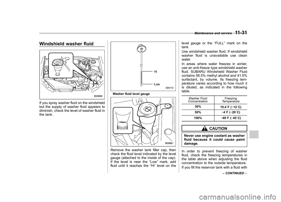
If you spray washer fluid on the windshield
but the supply of washer fluid appears to
diminish, check the level of washer fluid in
the tank.
Washer fluid level gauge
Remove the washer tank filler cap, then
check the fluid level indicated by the level
gauge (attached to the inside of the cap).
If the level is near the“Low ”mark, add
fluid until it reaches the “Hi ”level on the level gauge or the
“FULL ”mark on the
tank.
Use windshield washer fluid. If windshield
washer fluid is unavailable use clean
water.
In areas where water freezes in winter,
use an anti-freeze type windshield washer
fluid. SUBARU Windshield Washer Fluid
contains 58.5% methyl alcohol and 41.5%
surfactant, by volume. Its freezing tem-
perature varies according to how much it
is diluted, as indicated in the followingtable.
Washer Fluid
Concentration Freezing
Temperature
30% 10.48F( �12 8C)
50% �48F( �20 8C)
100% �49 8F( �45 8C)
CAUTION
Never use engine coolant as washer
fluid because it could cause paintdamage.
In order to prevent freezing of washer
fluid, check the freezing temperatures in
the table above when adjusting the fluid
concentration to the outside temperature.
If you fill the reservoir tank with a fluid with Maintenance and service
11-31
– CONTINUED –
Page 377 of 416
12-8Specifications
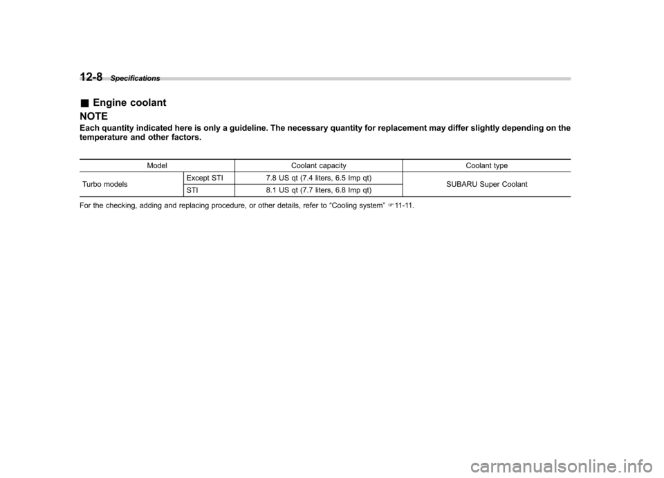
&Engine coolant
NOTE
Each quantity indicated here is only a guideline. The necessary quantity for replacement may differ slightly depending on the
temperature and other factors.
Model Coolant capacity Coolant type
Turbo models Except STI 7.8 US qt (7.4 liters, 6.5 Imp qt)
SUBARU Super Coolant
STI 8.1 US qt (7.7 liters, 6.8 Imp qt)
For the checking, adding and replacing procedure, or other details, refer to “Cooling system ”F 11-11.