2012 SUBARU FORESTER replace
[x] Cancel search: replacePage 407 of 438
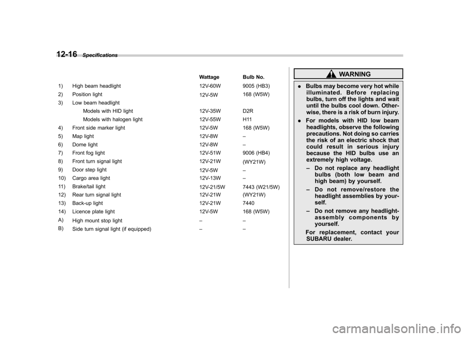
12-16Specifications
Wattage Bulb No.
1) High beam headlight 12V-60W 9005 (HB3)
2) Position light 12V-5W168 (W5W)
3) Low beam headlight
Models with HID light 12V-35W D2R
Models with halogen light 12V-55W H11
4) Front side marker light 12V-5W 168 (W5W)
5) Map light 12V-8W–
6) Dome light 12V-8W–
7) Front fog light 12V-51W 9006 (HB4)
8) Front turn signal light 12V-21W (WY21W)
9) Door step light 12V-5W–
10) Cargo area light 12V-13W–
11) Brake/tail light 12V-21/5W 7443 (W21/5W)
12) Rear turn signal light 12V-21W (WY21W)
13) Back-up light 12V-21W 7440
14) Licence plate light 12V-5W 168 (W5W)A) High mount stop light ––
B) Side turn signal light (if equipped) ––WARNING
. Bulbs may become very hot while
illuminated. Before replacing
bulbs, turn off the lights and wait
until the bulbs cool down. Other-
wise, there is a risk of burn injury.
. For models with HID low beam
headlights, observe the following
precautions. Not doing so carries
the risk of an electric shock that
could result in serious injury
because the HID bulbs use an
extremely high voltage. – Do not replace any headlight
bulbs (both low beam and
high beam) by yourself.
– Do not remove/restore the
headlight assemblies by your-self.
– Do not remove any headlight-
assembly components by yourself.
For replacement, contact your SUBARU dealer.
Page 408 of 438

CAUTION
Replace any bulb only with a new
bulb of the specified wattage. Using
a bulb of different wattage could
result in a fire. Specifications
12-17
Page 414 of 438

crease in temperature could cause
tread separation, and failure of the
tire(s). Possible resulting loss of
vehicle control could lead to anaccident. !Measuring and adjusting air
pressure to achieve proper in-
flation
Check and, if necessary, adjust the
pressure of each tire (including the
spare) at least once a month and
before any long journey. Check the
tire pressures when the tires are
cold. Use a pressure gauge to
adjust the tire pressures to the
specific values. Driving even a
short distance warms up the tires
and increases the tire pressures.
Also, the tire pressures are affected
by the outside temperature. It is
best to check tire pressure out-
doors before driving the vehicle.
When a tire becomes warm, the air
inside it expands, causing the tire
pressure to increase. Be careful not
to mistakenly release air from a
warm tire to reduce its pressure. &
Glossary of tire terminology
. Accessory weight
The combined weight (in excess of
those standard items which may be
replaced) of automatic transmis-
sion, power steering, power brakes,
power windows, power seats, radio,
and heater, to the extent that these
items are available as factory-in-
stalled equipment (whether in-
stalled or not). . Bead
The part of the tire that is made of
steel wires, wrapped or reinforced
by ply cords and that is shaped to fit
the rim.. Bead separation
A breakdown of the bond between
components in the bead.. Bias ply tire
A pneumatic tire in which the ply
cords that extend to the beads are
laid at alternate angles substantially
less than 90 degrees to the center-
line of the tread. . Carcass
The tire structure, except tread and sidewall rubber which, when in-
flated, bears the load. .
Chunking
The breaking away of pieces of the
tread or sidewall.. Cold tire pressure
The pressure in a tire that has been
driven less than 1 mile or has been
standing for three hours or more.. Cord
The strands forming the plies in the tire. . Cord separation
The parting of cords from adjacent
rubber compounds.. Cracking
Any parting within the tread, side-
wall, or inner liner of the tire
extending to cord material. . Curb weight
The weight of a motor vehicle with
standard equipment including the
maximum capacity of fuel, oil and
coolant, and if so equipped, air
conditioning and additional weight
optional engine.
Consumer information and Reporting safety defects
13-5
– CONTINUED –
Page 416 of 438

.Passenger car tire
A tire intended for use on passen-
ger cars, multipurpose passenger
vehicles, and trucks, that have a
gross vehicle weight rating (GVWR)
of 10,000 lbs (4,535 kg) or less. . Ply
A layer of rubber-coated parallel cords.. Ply separation
A parting of rubber compound
between adjacent plies.. Pneumatic tire
A mechanical device made of rub-
ber, chemicals, fabric and steel or
other materials, that, when
mounted on an automotive wheel,
provides the traction and contains
the gas or fluid that sustains theload. . Production options weight
The combined weight of those
installed regular production options
weighing over 5.1 lbs (2.3 kg) in
excess of those standard items
which they replace, not previously
considered in curb weight or acces- sory weight, including heavy duty
brakes, ride levelers, roof rack,
heavy duty battery, and special trim.
. Radial ply tire
A pneumatic tire in which the ply
cords that extend to the beads are
laid at substantially 90 degrees to
the centerline of the tread. . Recommended inflation pres-
sure
The cold inflation pressure recom-
mended by a vehicle manufacturer. . Reinforced tire
A tire designed to operate at higher
loads and at higher inflation pres-
sures than the corresponding stan-
dard tire. . Rim
A metal support for a tire or a tire
and tube assembly upon which the
tire beads are seated. . Rim diameter
Nominal diameter of the bead seat. . Rim size designation
Rim diameter and width. .
Rim type designation
The industry of manufacturer ’s des-
ignation for a rim by style or code. . Rim width
Nominal distance between rim flanges. . Section width
The linear distance between the
exteriors of the sidewalls of an
inflated tire, excluding elevations
due to labeling, decoration, or
protective bands. . Sidewall
That portion of a tire between the
tread and bead.. Sidewall separation
The parting of the rubber com-
pound from the cord material in
the sidewall.. Test rim
The rim on which a tire is fitted for
testing, and it may be any rim listed
as appropriate for use with that tire.. Tread
That portion of a tire that comes
into contact with the road.
Consumer information and Reporting safety defects
13-7
– CONTINUED –
Page 418 of 438

Table 1—Occupant loading and distribution for vehicle normal load for
various designated seating capacities
Designated seating
capacity, number of
occupants Vehicle normal load,
number of occupants Occupant distribution in a
normally loaded vehicle
2 through 4 2 2 in front.
5 through 10 3 2 in front, 1 in second seat.
11 through 15 5 2 in front, 1 in second
seat, 1 in third seat, 1 in
fourth seat.
16 through 22 7 2 in front, 2 in second
seat, 2 in third seat, 1 in
fourth seat.&
Tire care –maintenance and
safety practices
. Check on a daily basis that the
tires are free from serious damage,
nails, and stones. At the same time,
check the tires for abnormal wear. . Inspect the tire tread regularly
and replace the tires before their
tread wear indicators become visi-
ble. When a tire ’s tread wear
indicator becomes visible, the tire
is worn beyond the acceptable limit
and must be replaced immediately.
With a tire in this condition, driving
at even low speeds in wet weather
can cause the vehicle to hydro-
plane. Possible resulting loss of
vehicle control can lead to anaccident. . To maximize the life of each tire
and ensure that the tires wear
uniformly, it is best to rotate the
tires every 7,500 miles (12,000 km).
For information about the tire rota-
tion order, refer to “Tire rotation ”
F 11-35 .
Consumer information and Reporting safety defects
13-9
– CONTINUED –
Page 419 of 438

13-10Consumer information and Reporting safety defects
Replace any damaged or un-
evenly worn tires at the time of
rotation. After tire rotation, adjust
the tire pressures and make sure
the wheel nuts are correctly tigh-
tened. For information about the
tightening torque and tightening
sequence for the wheel nuts, referto “Flat tires ”F 9-6 .
& Vehicle load limit –how to
determine
The load capacity of your vehicle is
determined by weight, not by avail-
able cargo space. The load limit of
your vehicle is shown on the
vehicle placard attached to the
driver ’s side B-pillar. Locate the
statement “The combined weight
of occupants and cargo should
never exceed XXX kg or XXX lbs ”
on your vehicle ’s placard.
The vehicle placard also shows
seating capacity of your vehicle.
The total load capacity includes the
total weight of driver and all pas-
sengers and their belongings, any cargo, any optional equipment such
as a trailer hitch, roof rack or bike
carrier, etc., and the tongue load of
a trailer. Therefore cargo capacity
can be calculated by the followingmethod.
Cargo capacity = Load limit
(total
weight of occupants + total weight
of optional equipment + tongue
load of a trailer (if applicable))
For information about vehicle load-
ing, refer to “Loading your vehicle ”
F 8-12 .
For information about towing capa-
city and weight limits, refer to“ Trailer towing ”F 8-18 .
! Calculating total and load ca-
pacities varying seating con-
figurations
Calculate the available load capa-
city as shown in the following
examples: Example 1A
Vehicle capacity weight of the
vehicle is 900 lbs (408 kg), which
is indicated on the vehicle placard
with the statement
“The combined
weight of occupants and cargo
should never exceed 900 lbs or
408 kg ”.
For example, if the vehicle has one
occupant weighing 154 lbs (70 kg)
plus cargo weighing 662 lbs (300kg).
Page 427 of 438

14-2Index
A
ABS (Anti-lock Brake System) ..................................... 7-23
Warning light ......................................................... 3-19
Accessories ....................................................... 5-4, 11-45
Accessory power outlet ................................................. 6-9
Active head restraint ..................................................... 1-6
Air cleaner element ................................................... 11-15
Air conditioner Manual climate control system ................................... 4-8
Air filtration system ..................................................... 4-11
Airflow selection Automatic climate control system ............................... 4-6
Manual climate control system ................................... 4-8
Alarm system ............................................................ 2-14
All-Wheel Drive warning light ....................................... 3-21
Aluminum wheel ....................................................... 11-37
Cleaning ............................................................... 10-3
Antenna system ........................................................... 5-3
Anti-lock Brake System (ABS) ..................................... 7-23
Arming the system ..................................................... 2-15
Armrest ....................................................................... 1-8
Ashtray ..................................................................... 6-11
AT OIL TEMP warning light ......................................... 3-18
Audio Antenna system ....................................................... 5-3
Auxiliary input jack ................................................. 5-29
Bluetooth
®audio .................................................... 5-40
CD player operation ............................................... 5-22
Control button ........................................................ 5-37
FM/AM radio operation ........................................... 5-13
iPod
®operations .................................................... 5-32 Satellite radio operations
......................................... 5-18
Set ........................................................................ 5-4
USB storage device operations ................................ 5-32
Auto-dimming mirror/compass .............................. 3-37, 3-38
Automatic climate control system ................................... 4-6
Automatic headlight beam leveler ................................. 3-31
Warning light .......................................................... 3-22
Automatic transmission ............................................... 7-15
Fluid ........................................................... 11-20, 12-9
MANUAL mode ...................................................... 7-19
Oil temperature warning light (AT OIL TEMP) ............. 3-18
Select lever ........................................................... 7-16
Shift lock function ................................................... 7-17
SPORT mode ........................................................ 7-20
Automatic/Emergency Locking Retractor (A/ELR) ........... 1-13
Auxiliary input jack ...................................................... 5-29
BBattery .................................................................... 11-43
Drainage prevention function ..................................... 2-5
Jump starting ......................................................... 9-10
Replacement (remote engine start transmitter) ........... 7-12
Replacement (remote keyless entry system) .............. 2-10
Bluetooth
®audio ........................................................ 5-40
Booster seat .............................................................. 1-28
Bottle holder ............................................................... 6-9
Brake
Assist .................................................................... 7-22
Booster ....................................................... 7-22, 11-25
Fluid ........................................................... 11-23, 12-9
Pad and lining ...................................................... 11-28
Page 431 of 438

14-6Index
Hook Cargo tie-down ...................................................... 6-15
Coat ..................................................................... 6-13
Shopping bag ........................................................ 6-13
Towing and tie-down ............................................... 9-14
Horn ......................................................................... 3-47
Hose and connections ............................................... 11-14
I
Ignition switch .............................................................. 3-3
Light ....................................................................... 3-5
Illuminated entry .......................................................... 2-9
Illumination brightness control ...................................... 3-32
Immobilizer. ................................................................. 2-3
Indicator light (security indicator light) ....................... 3-23
Indicator light Coolant temperature low ......................................... 3-16
Cruise control ........................................................ 3-25
Cruise control set ................................................... 3-25
Front fog light ........................................................ 3-25
Headlight .............................................................. 3-25
High beam ............................................................ 3-25
Immobilizer. ........................................................... 3-23
Security ................................................................ 3-23
Select lever/Gear position ....................................... 3-24
SPORT mode ........................................................ 3-24
Turn signal ............................................................ 3-24
Vehicle Dynamics Control OFF ................................ 3-23
Vehicle Dynamics Control operation ......................... 3-23
Information display ..................................................... 3-26
Inside mirror .............................................................. 3-36 Interior lights
............................................................... 6-2
iiPod
®operations ........................................................ 5-32
J
Jack and jack handle ................................................... 9-5
Jack-up point .............................................................. 9-6
Jump starting ............................................................. 9-10
K
Key............................................................................ 2-2 Number .................................................................. 2-2
Reminder chime ...................................................... 3-5
Replacement. .......................................................... 2-3
Keyless entry system ................................................... 2-7
L
Leather seat materials ................................................. 10-5
License plate light ..................................................... 11-49
Light Cargo area .................................................... 6-3, 11-50
Control switch ........................................................ 3-29
Dome ............................................................ 6-2, 11-50
Door step ............................................................ 11-50
Front fog ............................................................... 3-32
Front position ......................................................... 3-30
Ignition switch ......................................................... 3-5
License plate ....................................................... 11-49
Map .............................................................. 6-3, 11-50