2012 SUBARU FORESTER fuel consumption
[x] Cancel search: fuel consumptionPage 113 of 438

Instruments and controlsInformation display ............................................ 3-26
Outside temperature indicator ............................ 3-27
Current fuel consumption (if equipped) ............... 3-28
Average fuel consumption .................................. 3-28
To turn off fuel consumption indicator display ............................................................. 3-28
Light control switch ........................................... 3-29
Headlights. ......................................................... 3-30
High/low beam change (dimmer) ......................... 3-30
Headlight flasher ................................................ 3-30
Daytime running light system (if equipped) ... ...... 3-31
Automatic headlight beam leveler (models with HID headlights) ................................................ 3-31
Turn signal lever ................................................ 3-31 Illumination brightness control
......................... 3-32
Front fog light switch (if equipped) .................. 3-32
Wiper and washer .............................................. 3-33
Windshield wiper and washer switches .............. 3-34
Rear window wiper and washer switch ............... 3-36
Mirrors ................................................................ 3-36
Inside mirror ...................................................... 3-36
Auto-dimming mirror/compass (if equipped) ....... 3-37
Auto-dimming mirror/compass with HomeLink
®(if equipped) .................................................... 3-38
Outside mirrors ................................................. 3-44
Defogger and deicer .......................................... 3-45
Tilt/telescopic steering wheel ........................... 3-47
Horn .................................................................... 3-47
Page 123 of 438

3-12Instruments and controls
&ECO gauge (models with type
A combination meter)
The unit displayed varies depending on
the model.
The ECO gauge shows the difference
between the average rate of fuel con-
sumption since the trip meter was last
reset and the current rate of fuel con-sumption.
The ECO gauge indicates the current fuel
efficiency as shown in the following chart.
Displayed unit Needle pointing
“ + ” side “-” side
MPG Better Poorer
l/100km Poorer BetterNOTE .
The ECO gauge shows only an
approximate indication of fuel effi-
ciency.. After resetting the trip meter, the
average rate of fuel consumption is not
shown until driving 0.6 mile (1 km).
Until that time, the ECO gauge does notoperate. Warning and indicator lights
Several of the warning and indicator lights
illuminate when the ignition switch is
initially turned to the
“ON ”position. This
permits checking the operation of thebulbs.
Apply the parking brake and turn the
ignition switch to the “ON ”position. For
the system check, the following lights
illuminate and turn off after several sec-
onds or after the engine has started.
: Seatbelt warning light (The seatbelt warning light turns off
only when the driver fastens theseatbelt.)
: Front passenger ’s seatbelt warning
light
(The seatbelt warning light turns off
only when the front seat passenger
fastens the seatbelt.)
: SRS airbag system warning light
ON /
: Front passenger ’s frontal airbag
ON indicator light
/: Front passenger ’s frontal airbag
OFF indicator light
: CHECK ENGINE warning light/Mal- function indicator light
Page 137 of 438

3-26Instruments and controls
CAUTION
To ensure safety, do not attempt to
set the time while driving, as an
accident from inadequate attention
to the road could result.
NOTE
If the battery is disconnected, the time
will be erased. After reconnecting the
battery, set the correct time. Information display
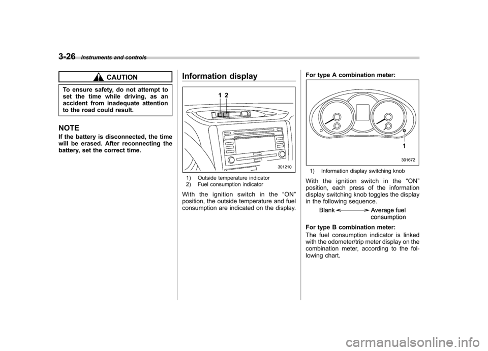
1) Outside temperature indicator
2) Fuel consumption indicator
Withtheignitionswitchinthe “ON ”
position, the outside temperature and fuel
consumption are indicated on the display. For type A combination meter:
1) Information display switching knob
With the ignition switch in the “ON ”
position, each press of the information
display switching knob toggles the display
in the following sequence.
For type B combination meter:
The fuel consumption indicator is linked
with the odometer/trip meter display on the
combination meter, according to the fol-
lowing chart.
Page 138 of 438

Odometer/
Trip meterFuel consumption indicator
A trip meter Average fuel consumption corresponding to the A trip meter
B trip meter Average fuel consumption corresponding to the B tripmeter
Odometer U.S-spec. models: Not indicated
Other models: Current fuel consumption &
Outside temperature indica- tor
1) U.S.-spec. models
2) Except U.S.-spec. models
The outside temperature indicator shows
the outside temperature in a range from� 22 to 122 8F( �30 to 50 8C).
The indicator can give a false reading
under any of the following conditions: . When there is too much sun.
. During idling; while running at low
speeds in a traffic jam; when the engine
is restarted immediately following a shut- down. . When the actual outside temperature
falls outside the specified indicator range. !
Road surface freeze warning indi- cation1) U.S.-spec. models
2) Except U.S.-spec. models
When the outside temperature drops to 37 8F(3 8C) or lower, the temperature
indication flashes to show that the road
surface may be frozen.
If the display has already indicated an
outside temperature of 37 8F(3 8C) or
lower, the indication does not flash even
when the outside temperature drops to37 8F(3 8C) or lower again, unless the
outside temperature has once increased
to 41 8F(5 8C) or higher.
If the outside temperature drops to 37 8F
(3 8C) or lower while the display is giving
an indication other than the outside Instruments and controls
3-27
– CONTINUED –
Page 139 of 438

3-28Instruments and controls
temperature, the display switches to the
outside temperature indication and flashes
for 5 seconds before returning to its
original indication. NOTE
The outside temperature indication
may differ from the actual outside
temperature. The road surface freeze
warning indication should be treated
only as a guide. Be sure to check the
condition of the road surface beforedriving. & Current fuel consumption (if equipped)
This indication shows the rate of fuel
consumption at the present moment. NOTE
The indicated values vary in accor-
dance with changes in the vehicle
’s
running conditions. Also, the indicated
values may differ slightly from the
actual values and should thus be
treated only as a guide. & Average fuel consumption
1) U.S.-spec. models
2) Except U.S.-spec. models
This indication shows the average rate of
fuel consumption since the trip meter was
last reset.
When either of the trip meter indications is
reset, the corresponding average fuel
consumption value is also reset. NOTE .
The indicated values vary in accor-
dance with changes in the vehicle ’s
running conditions. Also, the indicated
values may differ slightly from the
actual values and should thus be
treated only as a guide.. When either trip meter indication is
reset, the average fuel consumption
corresponding to that trip meter indica-
tion is not shown until the vehicle has
subsequently covered a distance of 1
mile (or 1 km).
& To turn off fuel consumption
indicator display
The fuel consumption indicator display
can be turned off.
To turn off this display, turn the ignition
switch to the “LOCK ”position and press
the “+ ” button adjacent to the information
display for approximately 5 seconds. The
information display and the clock display
will blink for 3 seconds and then the fuel
consumption display will turn off.
To restore the indicator, once again pressthe “+ ” button for approximately 5 sec-
onds. NOTE . The initial display setting of the fuel
consumption indicator of your vehicle
Page 140 of 438

has been set to operational at the time
of shipment from the factory..The average fuel consumption is
calculated even while the indicator is
not displayed.. Even if you turn off the fuel con-
sumption indicator, the fuel consump-
tion indicator will automatically turn on
when the battery voltage is stopped
and then reapplied due to battery
replacement or fuse replacement. Light control switch
The light control switch operates when the
ignition key is inserted into the ignitionswitch.
Regardless of the position of the light
control switch, the illuminated lights are
turned off when the ignition key is
removed from the ignition switch. NOTE
Even if the key is removed from the
ignition switch, the lights can be illu-
minated by once setting the light con-
trol switch to the
“OFF ”position and
then to the “
”or “”position. In
this case, if the driver ’s door is opened,
the chirp sound will inform the driver
that the lights are illuminated.
CAUTION
. Use of any lights for a long period
of time while the engine is not
running can cause the battery todischarge.
. Before leaving the vehicle, make
sure that the light control switch
is turned to the “OFF ”position. If
the vehicle is left unattended for
a long time with the light control
switch set to a position other than
“OFF ”, the battery may be
discharged. Instruments and controls
3-29
– CONTINUED –
Page 289 of 438

8-2Driving tips
New vehicle break-in driving –the first 1,000 miles (1,600
km)
The performance and long life of your
vehicle are dependent on how you handle
and care for your vehicle while it is new.
Follow these instructions during the first
1,000 miles (1,600 km): . Do not race the engine. And do not
allow engine speed to exceed 4,000 rpm
except in an emergency. . Do not drive at one constant engine or
vehicle speed for a long time, either fast or
slow. . Avoid starting suddenly and rapid
acceleration, except in an emergency.. Avoid hard braking, except in an
emergency.
The same break-in procedures should be
applied to an overhauled engine, newly
mounted engine or when brake pads or
brake linings are replaced with new ones. Fuel economy hints
The following suggestions will help to save fuel. .
Select the proper gear position for the
speed and road conditions.. Avoid sudden acceleration or decelera-
tion. Always accelerate gently until you
reach the desired speed. Then try to
maintain that speed for as long aspossible. . Do not pump the accelerator and avoid
racing the engine.. Avoid unnecessary engine idling.
. Keep the engine properly tuned.
. Keep the tires inflated to the correct
pressure shown on the tire placard, which
is located under the door latch on thedriver ’s side. Low pressure will increase
tire wear and fuel consumption. . Use the air conditioner only when
necessary.. Keep the front and rear wheels in
proper alignment.. Avoid carrying unnecessary luggage or
cargo. Engine exhaust gas (carbon
monoxide)
WARNING
. Never inhale engine exhaust gas.
Engine exhaust gas contains
carbon monoxide, a colorless
and odorless gas which is dan-
gerous, or even lethal, if inhaled.
. Always properly maintain the en-
gine exhaust system to prevent
engine exhaust gas from enter-
ing the vehicle.
. Never run the engine in a closed
space, such as a garage, except
for the brief time needed to drive
the vehicle in or out of it.
. Avoid remaining in a parked
vehicle for a lengthy time while
the engine is running. If that is
unavoidable, then use the venti-
lation fan to force fresh air into
the vehicle.
. Always keep the front ventilator
inlet grille free from snow, leaves
or other obstructions to ensure
that the ventilation system al-
ways works properly.
. If at any time you suspect that
Page 348 of 438

Engine oil NOTE .The engine oil consumption rate is
not stabilized, and therefore cannot be
determined until the vehicle has tra-
veled at least several thousand miles
(kilometers). Even after break-in, when
the vehicle is used under severe driv-
ing conditions such as those men-
tionedintheWarrantyandMainte-
nance Booklet, engine oil is consumed
or deteriorated more quickly than un-
der normal driving conditions. If you
drive your vehicle under these severe
conditions, you should check the oil
level at least at every second fuel fill-up
time, and change the oil more fre-
quently. Please refer to the Warranty
and Maintenance Booklet for more de-tails.. If the oil consumption rate seems
abnormally high after the break-in
period, for example more than 1 quart
per 1,200 miles (1 liter per 2,000 kilo-
meters), contact your SUBARU dealer. &
Checking the oil level
Check the engine oil level at each fuelstop.
1. Park the vehicle on a level surface and
stop the engine. Wait a few minutes for the
oil to drain back into the oil pan.
Turbo models
1) Oil level gauge
2) Oil filler cap
Non-turbo models
1) Oil level gauge
2) Oil filler cap
3) Oil filter
2. Pull out the level gauge, wipe it clean,
and insert it again. Maintenance and service
11-9
– CONTINUED –