2012 SSANGYONG RODIUS AUX
[x] Cancel search: AUXPage 157 of 715

01-150000-00
7. CODING AND INITIALIZATION
1) Engine Variant Coding
Unit Selection Description
PTC auxiliary heater NO For PTC auxiliary heaterequipped
vehicle, select"YES".
YES
Glow plug Relay (K-line) Select "AQGS".
AQGS (CAN)
Transmission MT 5-speed Select the appropriate system.
MT 6-speed
AT 5-speed (DC 5AT)
AT 6-speed (DSI 6AT)
AT 7-speed (DC 7AT)
Pressure sensor
forA/C refrigerantNOSelect “Refrigerant pressure sensor”.
Refrigerant Pressure Sensor
Immobilizer NO Select "YES" if the vehicle has
immobilizer.
YES
Vehicle speed input
typeCAN Select "CAN" if the vehicle has ABS or
ESP
WIRE
Cooling fan Relay Select "PWM".
PWM
Auto cruise NO Select "YES" if the vehicle hascruise
control.
YES
Engine level control NO Select "NO".
YES
G-sensor NOABS: Select “NO”.
4WD ABS or ESP: Select “YES”.
YES
SMART key NO Select "NO".
YES
Page 195 of 715

02-38
4) Features
Reduced vibration noise from the powertrain by blocking the torsional vibrations
Enhanced vehicle silence and riding comforts: reduced engine torque fluctuation
Reduced shifting shocks
Smooth acceleration and deceleration -
-
-
-
5) Advantages
Improved torque response by using 3-stage type spring: Strengthens the torque response in all
ranges (low, medium, and high speed) by applying respective spring constant at each range.
Stable revolution of the primary and secondary wheel by using planetary gear: Works as
auxiliary damper against spring changes
Less heat generation due to no direct friction against spring surface: Plastic material is covered
on the spring outer surface
Increased durability by using plastic bushing (extends the lifetime of grease) -
-
-
-
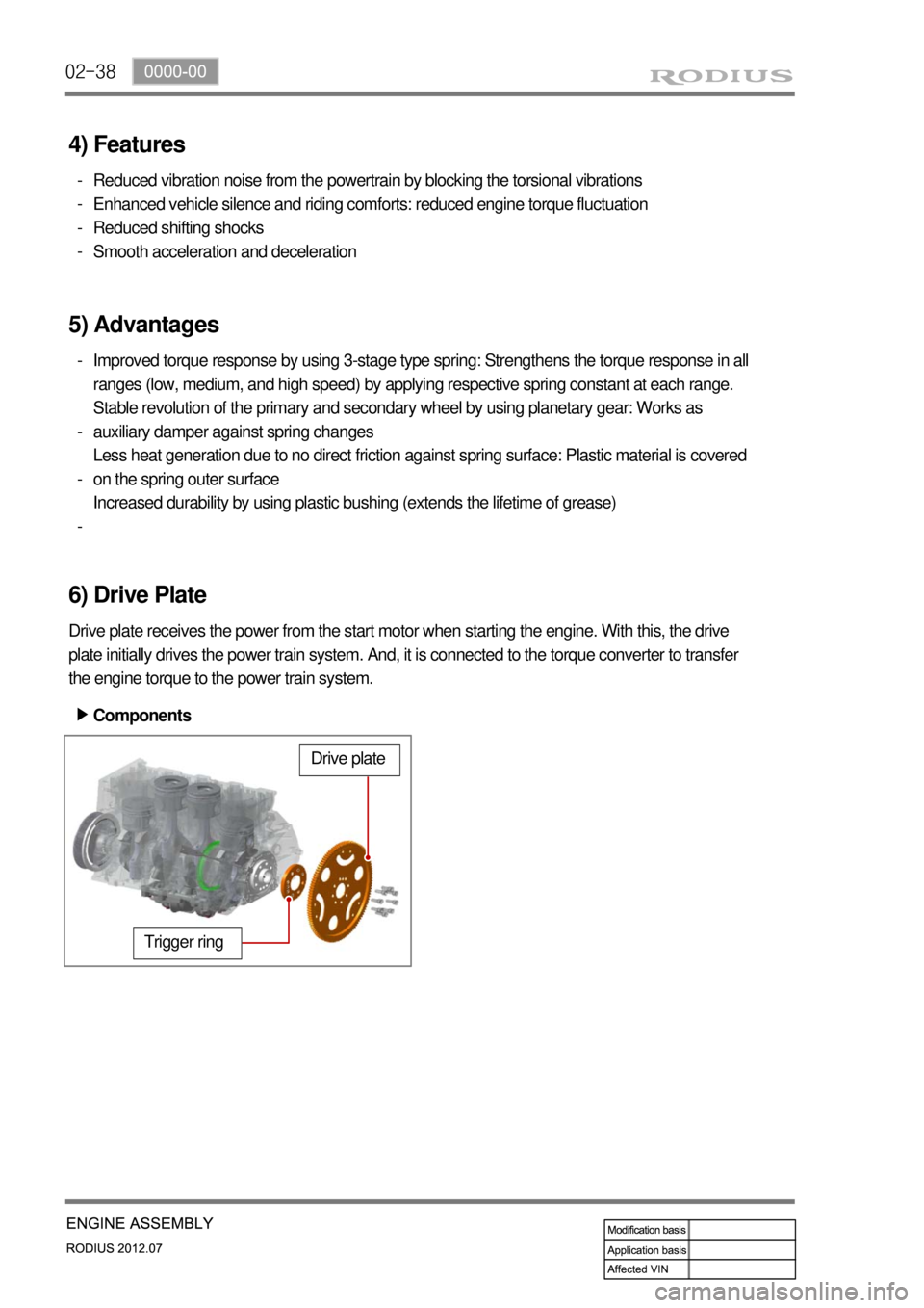
6) Drive Plate
Drive plate receives the power from the start motor when starting the engine. With this, the drive
plate initially drives the power train system. And, it is connected to the torque converter to transfer
the engine torque to the power train system.
Trigger ring
Drive plate
Components ▶
Page 269 of 715

08-4
2. INSPECTION
Possible Cause Action
Coolant level
is
too low- Leak from the radiator
- Leak from the coolant auxiliary tank
- Leak from the heater core- Change the radiator
- Change the coolant auxiliary tank
- Change the heater
- Leak from the coolant hose
connections
- Damaged coolant hose - Reconnect the hose or replace
the clamp
- Change the hose
- Leak from the water pump gasket
- Leak from the water pump internal
seal- Change the gasket
- Change the water pump
- Leak from the water inlet cap
- Leak from the thermostat housing- Change the water inlet cap
gasket
- Change the thermostat sealing
- Incorrect tightening torque of the
cylinder head bolts
- Damaged cylinder head gasket- Tighten the bolts to the specified
torque
- Change the cylinder head gasket
Coolant
temperature is
too high- Coolant leakage (Coolant level is low)
- Improper coolant mixture ratio
- Kinked coolant hose- Add coolant
- Check the coolant concentration
(Anti-freeze)
- Repair or replace the hose
- Defective thermostat
- Defective water pump
- Defective radiator
- Defective coolant auxiliary tank or tank
cap- Change the thermostat
- Change the water pump
- Change the radiator
- Change the coolant auxiliary tank
or tank cap
- Cracks on the cylinder block or
cylinder head
- Clogged coolant passages in the
cylinder block or cylinder head- Change cylinder block or cylinder
head
- Clean the coolant passage
- Clogged radiator core - Clean the radiator core
- Improper operation of cooling fan - Replace the cooling fan or repair
the related circuit
- Defective temperature sensor or
faulty wiring- Replace the sensor or repair the
related wiring
Coolant
temperature is
too low- Thermostat is stuck open - Change the thermostat
- Improper operation of cooling fan - Replace the cooling fan or repair
the related circuit
- Defective temperature sensor or faulty
wiring- Replace the sensor or repair the
related wiring
Page 271 of 715

08-6
2) Leak Test
Release the pressure in the system by
loosening the pressure cap of the coolant
reservoir slightly. Then, remove the pressure
cap completely. 1.
Never open the cap until the coolant
temperature becomes under 90℃ to
prevent any burn.
Add the coolant so that the coolant level is
between MAX and MIN mark on the
coolant auxiliary tank.
Connect the tester to the tank filler and
apply pressure (1.4 bar).
Check all the coolant hoses, pipes and
connections for leaks when the pressure of
the tester drops, and replace or tighten, if
necessary. 2.
3.
4.
3) Thermostat
Immerse the thermostat into the water. Heat
the water and check the valve opening
temperature.
Valve opening
temperature 90 ± 2℃
Page 310 of 715

13-51793-00
EGR pipe
Transports the exhaust gas from the EGR
cooler and EGR bypass valve to the intake
duct.E-EGR valve
Receives the electric signal from the ECU to
control the valve.
E-EGR cooler and bypass valve
The cooler lowers the high temperature of the
exhaust gas and the bypass valve directly
supplies the exhaust gas to the intake duct
without passing through the EGR cooler to
reduce the emission of exhaust gas before
warming up the engine.HFM sensor
Used as a main map value to control the EGR.
The coolant temperature, engine rpm, engine
load, intake air temperature (HFM: decreased
at 60˚C or more), atmospheric pressure
(atmospheric pressure sensor: altitude
compensation) are used as auxiliary map
values.
2) Location and Components
See the section "Engine control" for E-EGR
valve control logic.EGR coolerEGR bypass
For details, see the section "Engine control". *
Page 312 of 715

13-71793-00
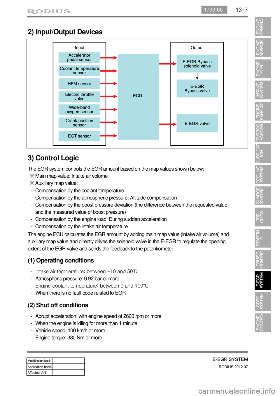
2) Input/Output Devices
3) Control Logic
The EGR system controls the EGR amount based on the map values shown below:
Main map value: Intake air volume
Auxiliary map value: ※
※
Compensation by the coolant temperature
Compensation by the atmospheric pressure: Altitude compensation
Compensation by the boost pressure deviation (the difference between the requested value
and the measured value of boost pressure)
Compensation by the engine load: During sudden acceleration
Compensation by the intake air temperature -
-
-
-
-
The engine ECU calculates the EGR amount by adding main map value (intake air volume) and
auxiliary map value and directly drives the solenoid valve in the E-EGR to regulate the opening
extent of the EGR valve and sends the feedback to the potentiometer.
(1) Operating conditions
Intake air temperature: between -10 and 50℃
Atmospheric pressure: 0.92 bar or more
Engine coolant temperature: between 0 and 100°C
When there is no fault code related to EGR -
-
-
-
(2) Shut off conditions
Abrupt acceleration: with engine speed of 2600 rpm or more
When the engine is idling for more than 1 minute
Vehicle speed: 100 km/h or more
Engine torque: 380 Nm or more -
-
-
-
Page 336 of 715

15-110000-00
2) ECU Control
(1) Function
a. ECU Function
ECU receives and analyzes signals from various sensors and then modifies those signals into
permissible voltage levels and analyzes to control respective actuators.
ECU microprocessor calculates injection period and injection timing proper for engine piston speed and
crankshaft angle based on input data and stored specific map to control the engine power and emission
gas.
Output signal of the ECU microprocessor drives pressure control valve to control the rail pressure and
activates injector solenoid valve to control the fuel injection period and injection timing; so controls
various actuators in response to engine changes. Auxiliary function of ECU has adopted to reduce
emission gas, improve fuel economy and enhance safety, comforts and conveniences. For example,
there are EGR, booster pressure control, autocruise (export only) and immobilizer and adopted CAN
communication to exchange data among electrical systems (automatic T/M and brake system) in the
vehicle fluently. And Scanner can be used to diagnose vehicle status and defectives.
<00760097008c00990088009b00900095008e0047009b008c00940097008c00990088009b009c0099008c0047009900880095008e008c00470096008d0047006c006a007c00470090009a0047009500960099009400880093009300a000470054005b005700
47009b009600470052005f005c00b6006a004700880095008b> protected from factors like oil,
water and electromagnetism and there should be no mechanical shocks.
To control the fuel volume precisely under repeated injections, high current should be applied instantly
so there is injector drive circuit in the ECU to generate necessary current during injector drive stages.
Current control circuit divides current applying time (injection time) into full-in-current-phase and hold-
current-phase and then the injectors should work very correctly under every working condition.
b. Control Function
Controls by operating stages
To make optimum combustion under every operating stage, ECU should calculate proper injection
volume in each stage by considering various factors.
Starting injection volume control
During initial starting, injecting fuel volume will be calculated by function of temperature and engine
cranking speed. Starting injection continues from when the ignition switch is turned to ignition
position to till the engine reaches to allowable minimum speed.
Driving mode control
If the vehicle runs normally, fuel injection volume will be calculated by accelerator pedal travel and
engine rpm and the drive map will be used to match the drivers inputs with optimum engine power. -
-
-