Page 619 of 715
09-114891-01
(3) ESP Control
The ESP (Electronic Stability Program) has been developed to help a driver avoid danger of losing
control of the vehicle stability due to understeer or oversteer during cornering. The yaw rate sensor,
lateral sensor and longitudinal sensor in the sensor cluster and the steering wheel angle sensor
under the steering column detect the vehicle conditions when the inner or outer wheels are
spinning during oversteer, understeer or cornering. The ESP ECU controls against oversteer or
understeer during cornering by controlling the vehicle stability using input values from these
sensors and applying the braking force to the corresponding wheels independently. The system
also controls the engine power right before the wheel spin synchronized to decelerate the vehicle
automatically in order to maintain the vehicle stable during cornering.
Page 632 of 715

10-34891-01
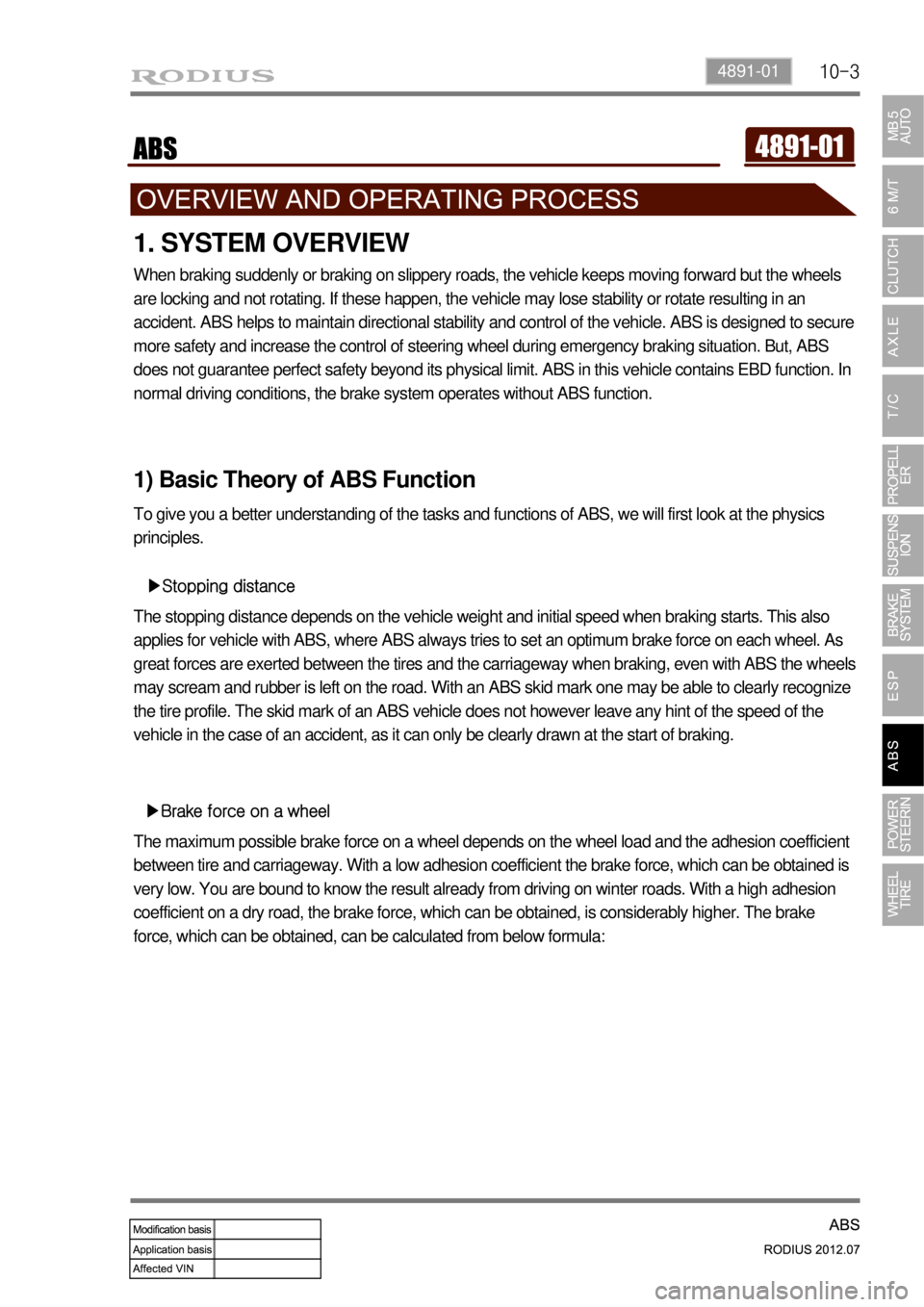
1. SYSTEM OVERVIEW
When braking suddenly or braking on slippery roads, the vehicle keeps moving forward but the wheels
are locking and not rotating. If these happen, the vehicle may lose stability or rotate resulting in an
accident. ABS helps to maintain directional stability and control of the vehicle. ABS is designed to secure
more safety and increase the control of steering wheel during emergency braking situation. But, ABS
does not guarantee perfect safety beyond its physical limit. ABS in this vehicle contains EBD function. In
normal driving conditions, the brake system operates without ABS function.
1) Basic Theory of ABS Function
To give you a better understanding of the tasks and functions of ABS, we will first look at the physics
principles.
▶Stopping distance
The stopping distance depends on the vehicle weight and initial speed when braking starts. This also
applies for vehicle with ABS, where ABS always tries to set an optimum brake force on each wheel. As
great forces are exerted between the tires and the carriageway when braking, even with ABS the wheels
may scream and rubber is left on the road. With an ABS skid mark one may be able to clearly recognize
the tire profile. The skid mark of an ABS vehicle does not however leave any hint of the speed of the
vehicle in the case of an accident, as it can only be clearly drawn at the start of braking.
▶Brake force on a wheel
The maximum possible brake force on a wheel depends on the wheel load and the adhesion coefficient
between tire and carriageway. With a low adhesion coefficient the brake force, which can be obtained is
very low. You are bound to know the result already from driving on winter roads. With a high adhesion
coefficient on a dry road, the brake force, which can be obtained, is considerably higher. The brake
force, which can be obtained, can be calculated from below formula:
Page 641 of 715
11-34610-00
1. SPECIFICATIONS
Description Specification
Steering wheelType 4-spoke type
Outer diameter (mm) 390
Steering gear boxType Rack and pinion type
Steering angleInner36.4°
Outer31.5°
Steering oil pumpType Vane type
Maximum pressure (kgf/cm2)90±3
Pulley size (mm)Ø115
Operating temperature-40℃ ~ 150℃
Steering oilType S-PSF3
Capacity (L) approx. 1.1
Minimum turning radius (m) 6.08
Tilting angle±3°
Page 642 of 715
11-4
2. TIGHTENING TORQUE
DescriptionKgf·m N·m
Steering column shaftSteering column mounting bolt 2.0 ~ 2.5 19.6 ~ 24.5
Steering wheel and steering column shaft
lock nut4.0 ~ 6.0 39.2 ~ 58.8
Steering wheel and air bag module
mounting bolt0.7 ~ 1.1 6.8 ~ 10.8
Steering column and lower shaft
connection bolt.1.8 ~ 2.5 17.6 ~ 24.5
Power steering gear
boxSteering gear box and gear box cross
member mounting bolt7.0 ~ 9.0 68.6 ~ 88.2
Steering gear box and lower shaft
connection bolt2.5 ~ 3.0 24.5 ~ 29.4
Tie rod end and knuckle connection nut 3.5 ~ 4.5 34.3 ~ 44.1
Tie rod end lock nut 6.5 ~ 8.0 63.7 ~ 78.4
Steering gear box and pressure hose
connection nut3.2 ~ 3.8 31.4 ~ 37.2
Steering gear box and return line
connection nut3.2 ~ 3.8 31.4 ~ 37.2
Power steering pumpEye bolt for oil supply pipe to power
steering pump5.5 ~ 6.5 53.9 ~ 63.7
Power steering pump mounting bolt 2.0 ~ 2.5 19.6 ~ 24.5
Power steering line Return line and clip connection bolt 1.2 ~ 1.8 11.7 ~ 17.6
Page 643 of 715

11-54610-00
3. TROUBLESHOOTING
Problem Possible Cause Action
Movements of steering
feels heavyUnregular wear or binding of steering ball joint
due to lack of lubrication or foreign material
insertionLubricate or replace
Damaged or defective steering gear Replace the steering gear
assembly
Incorrect steering pinion preload Adjust
Defective steering shaft join Replace
leakage of steering fluid Repair or replace
Insuffcient steering fluid or air insertionFill up fluid or bleed air
Defective steering oil pump Replace
Damaged or loosened pump drive belt
Adjust or replace
Clogging of fluid line Repair or replace
Damaged wheel or tire Repair or replace
Defective suspension Repair or replace
Steering wheel pulls to
one sideDamaged steering linkage Replace
Damaged wheel or tire Repair or replace
Defective brake system Repair or replace
Defective suspension Repair or replace
Excessive free play of
steering wheelWorn steering gear Replace the steering gear
assembly
Worn or damaged steering ball joint Replace
Looseness of steering gear box Retighten
Poor returning of steering
wheelBroken or binding of steering ball joint Replace
Improper correct steering pinion preload Replace the steering gear
assembly
Damaged wheel or tire Repair or replace
Defective suspension Repair or replace
Page 644 of 715

11-6
Problem Possible Cause Action
Excessive vibration of
steering wheel (shimming)Broken steering linkage Replace
Looseness of steering gear box Retighten
Broken or binding of steering ball joint Replace
Worn or damaged front wheel bearing Replace
Damaged wheel or tire Repair or replace
Defective suspension Repair or replace
Abnormal noise from
steering systemLooseness of steering gear box Retighten
Defective steering gear Replace the gear
assembly
Interference between steering column and
partsRepair
Looseness of steering linkage Retighten
Loosened or damaged oil pump drive belt Repair or replace
Looseness of oil pump bracket Retighten
Looseness of oil pump Retighten
Air insertion into system Bleed air
Defective oil pump Replace
Abnormal noise when
turning steering wheelLooseness of steering column Retighten
Worn or damaged steering shaft bearing Replace the steering
column
Looseness of intermediate shaft Retighten
Too heavy steering wheel Worn or damaged steering shaft bearing Replace the steering
column
Ignition key cannot be
inserted into key cylinderDefective lock cylinder Replace the steering
column
Defective ignition switch Replace the ignition switch
Page 645 of 715

11-74610-00
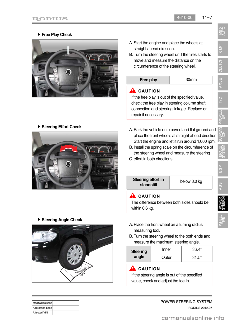
Free Play Check ▶
Start the engine and place the wheels at
straight ahead direction.
Turn the steering wheel until the tires starts to
move and measure the distance on the
circumference of the steering wheel. A.
B.
Free play30mm
If the free play is out of the specified value,
check the free play in steering column shaft
connection and steering linkage. Replace or
repair if necessary.
Steering Effort Check ▶
Park the vehicle on a paved and flat ground and
place the front wheels at straight ahead direction.
Start the engine and let it run around 1,000 rpm.
Install the spring scale on the circumference of
the steering wheel and measure the steering
effort in both directions. A.
B.
C.
Steering effort in
standstillbelow 3.0 kg
The difference between both sides should be
within 0.6 kg.
Steering Angle Check ▶
Place the front wheel on a turning radius
measuring tool.
Turn the steering wheel to the both ends and
measure the maximum steering angle. A.
B.
Steering
angleInner36.4°
Outer31.5°
If the steering angle is out of the specified
value, check and adjust the toe-in.
Page 646 of 715

11-8
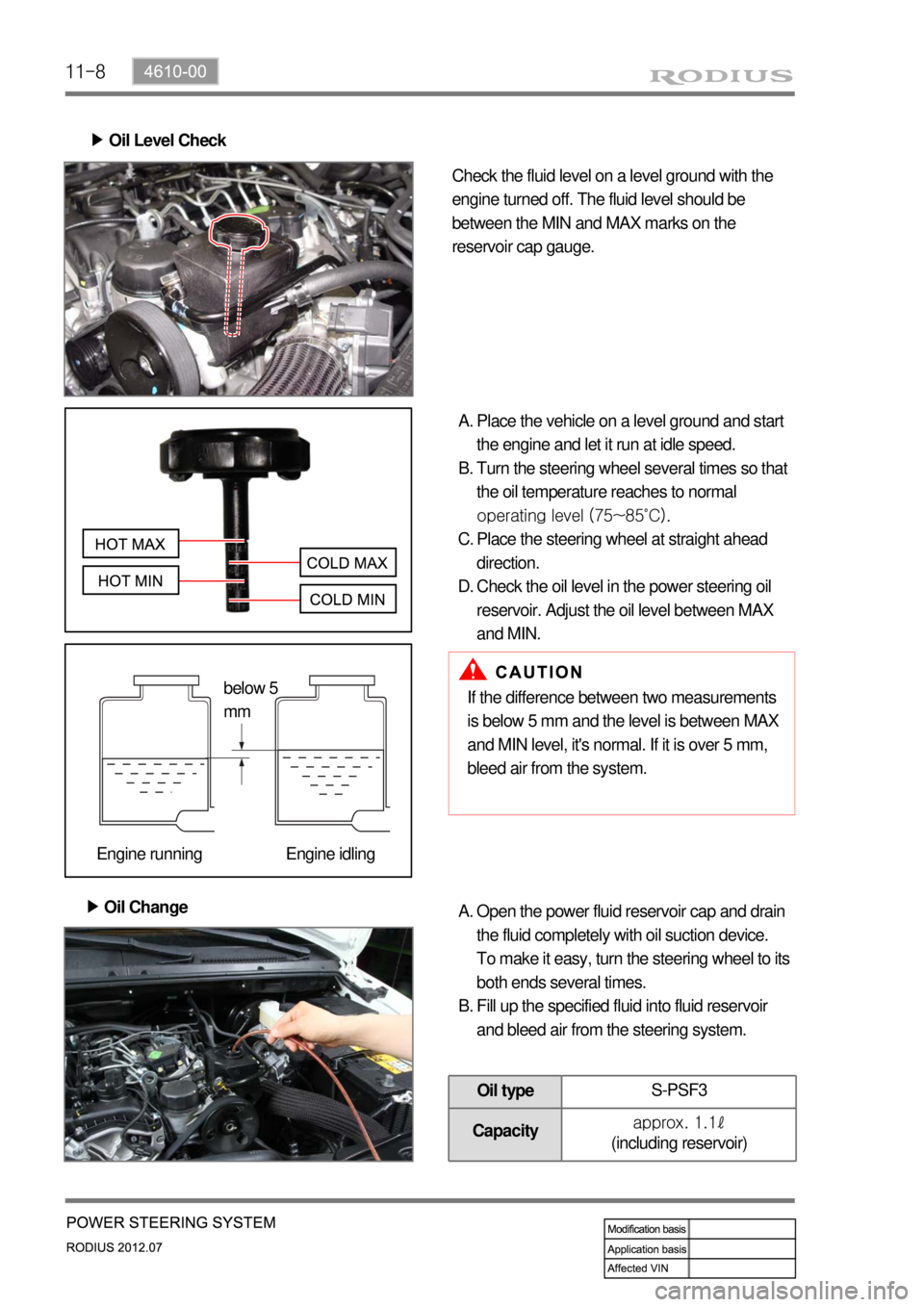
Oil Level Check ▶
Check the fluid level on a level ground with the
engine turned off. The fluid level should be
between the MIN and MAX marks on the
reservoir cap gauge.
Place the vehicle on a level ground and start
the engine and let it run at idle speed.
Turn the steering wheel several times so that
the oil temperature reaches to normal
operating level (75~85˚C).
Place the steering wheel at straight ahead
direction.
Check the oil level in the power steering oil
reservoir. Adjust the oil level between MAX
and MIN. A.
B.
C.
D.
Oil Change ▶
If the difference between two measurements
is below 5 mm and the level is between MAX
and MIN level, it's normal. If it is over 5 mm,
bleed air from the system.
Open the power fluid reservoir cap and drain
the fluid completely with oil suction device.
To make it easy, turn the steering wheel to its
both ends several times.
Fill up the specified fluid into fluid reservoir
and bleed air from the steering system. A.
B.
Oil typeS-PSF3
Capacityapprox. 1.1ℓ
(including reservoir)
below 5
mm
Engine running Engine idling