Page 403 of 715

08-6
3. IGNITION SYSTEM OPERATION
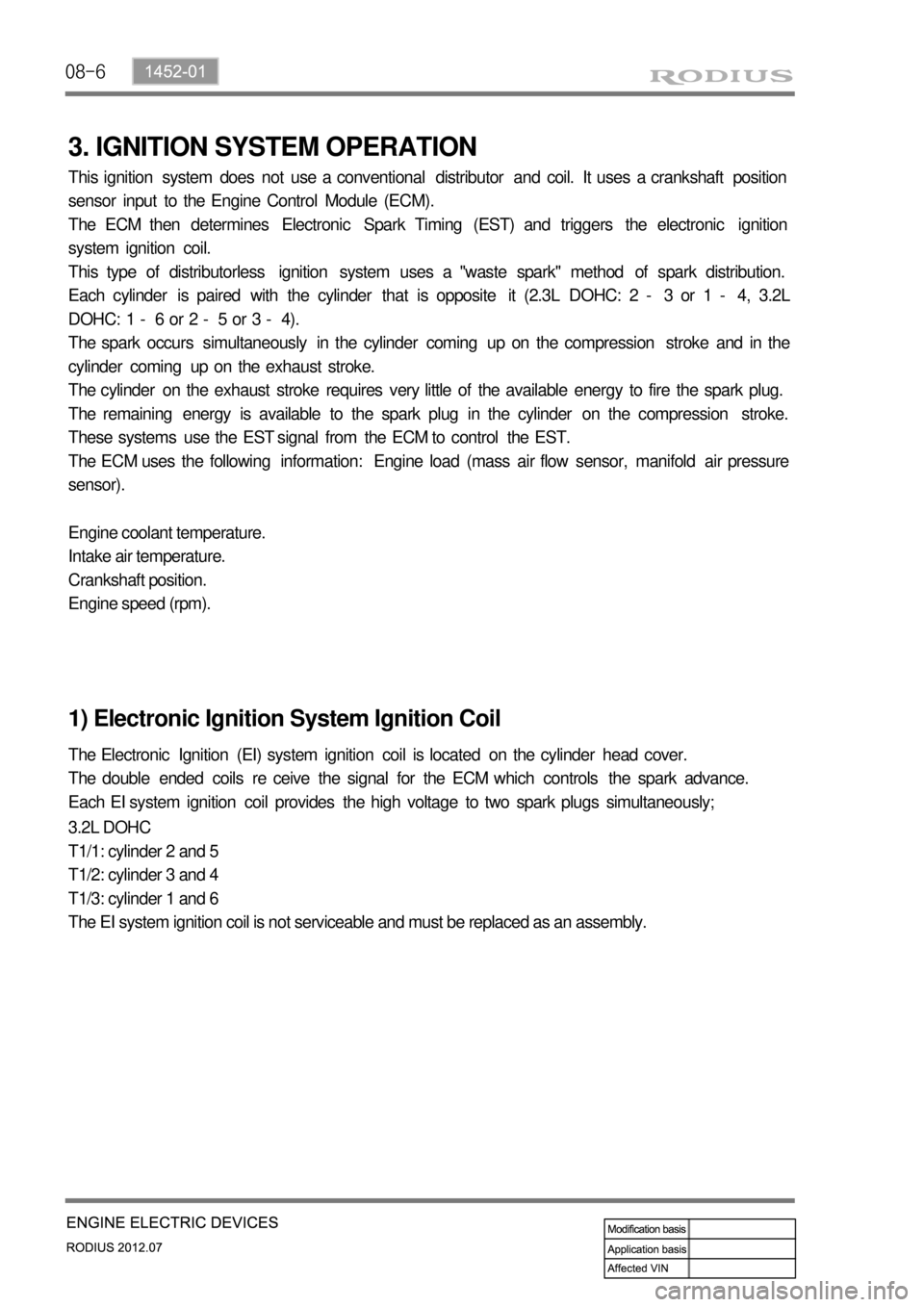
This ignition system does not use a conventional distributor and coil. It uses a crankshaft position
sensor input to the Engine Control Module (ECM).
The ECM then determines Electronic Spark Timing (EST) and triggers the electronic ignition
system ignition coil.
This type of distributorless ignition system uses a "waste spark" method of spark distribution.
Each cylinder is paired with the cylinder that is opposite it (2.3L DOHC: 2 - 3 or 1 - 4, 3.2L
DOHC: 1 - 6 or 2 - 5 or 3 - 4).
The spark occurs simultaneously in the cylinder coming up on the compression stroke and in the
cylinder coming up on the exhaust stroke.
The cylinder on the exhaust stroke requires very little of the available energy to fire the spark plug.
The remaining energy is available to the spark plug in the cylinder on the compression stroke.
These systems use the EST signal from the ECM to control the EST.
The ECM uses the following information: Engine load (mass air flow sensor, manifold air pressure
sensor).
Engine coolant temperature.
Intake air temperature.
Crankshaft position.
Engine speed (rpm).
1) Electronic Ignition System Ignition Coil
The Electronic Ignition (EI) system ignition coil is located on the cylinder head cover.
The double ended coils re ceive the signal for the ECM which controls the spark advance.
Each EI system ignition coil provides the high voltage to two spark plugs simultaneously;
3.2L DOHC
T1/1: cylinder 2 and 5
T1/2: cylinder 3 and 4
T1/3: cylinder 1 and 6
The EI system ignition coil is not serviceable and must be replaced as an assembly.
Page 524 of 715
01-53650-01
2. SPECIAL SERVICE TOLLS
Part Name/Part Number Description
W126 589 62 00
HandleInstall and remove the torque converter
W116 589 06 59 00
SupportSupport the transmission
W140 589 12 15 00
DriftInstall the seal ring
W001 589 50 33 00
PullerInstall and remove the transmission housing ball bearing
Page 541 of 715

02-33170-01
Description Specification
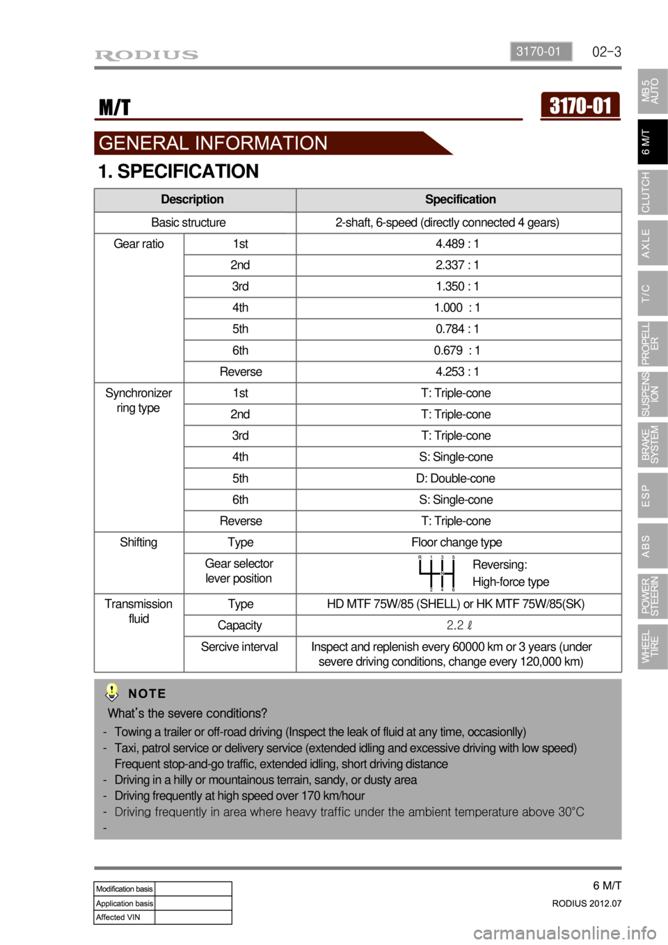
Basic structure 2-shaft, 6-speed (directly connected 4 gears)
Gear ratio 1st 4.489 : 1
2nd 2.337 : 1
3rd 1.350 : 1
4th 1.000 : 1
5th 0.784 : 1
6th 0.679 : 1
Reverse 4.253 : 1
Synchronizer
ring type1st T: Triple-cone
2nd T: Triple-cone
3rd T: Triple-cone
4th S: Single-cone
5th D: Double-cone
6th S: Single-cone
Reverse T: Triple-cone
Shifting Type Floor change type
Gear selector
lever position
Transmission
fluidType HD MTF 75W/85 (SHELL) or HK MTF 75W/85(SK)
Capacity2.2 ℓ
Sercive interval Inspect and replenish every 60000 km or 3 years (under
severe driving conditions, change every 120,000 km)
1. SPECIFICATION
Reversing:
High-force type
What’s the severe conditions?
Towing a trailer or off-road driving (Inspect the leak of fluid at any time, occasionlly)
Taxi, patrol service or delivery service (extended idling and excessive driving with low speed)
Frequent stop-and-go traffic, extended idling, short driving distance
Driving in a hilly or mountainous terrain, sandy, or dusty area
Driving frequently at high speed over 170 km/hour
<006b00990090009d00900095008e0047008d0099008c0098009c008c0095009b009300a0004700900095004700880099008c00880047009e008f008c0099008c0047008f008c0088009d00a00047009b00990088008d008d0090008a0047009c0095008b00
8c00990047009b008f008c00470088009400890090008c0095>t temperature above 30°C -
-
-
-
-
-
Page 543 of 715

02-53170-01
Part No. & Name Appearance Description
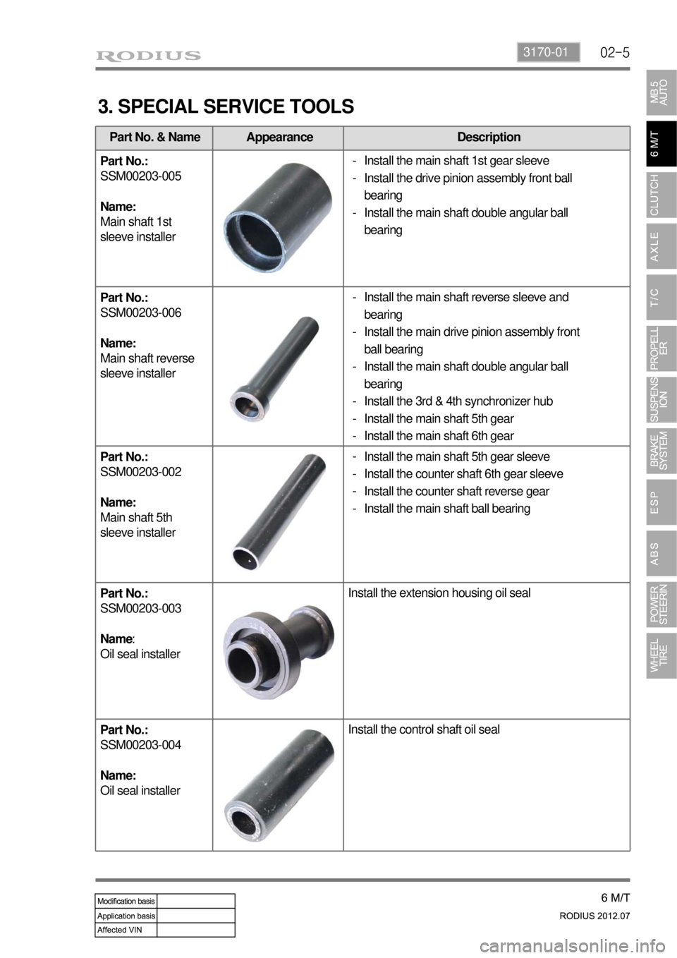
Part No.:
SSM00203-005
Name:
Main shaft 1st
sleeve installer
Part No.:
SSM00203-006
Name:
Main shaft reverse
sleeve installer
Part No.:
SSM00203-002
Name:
Main shaft 5th
sleeve installer
Part No.:
SSM00203-003
Name:
Oil seal installerInstall the extension housing oil seal
Part No.:
SSM00203-004
Name:
Oil seal installerInstall the control shaft oil seal
3. SPECIAL SERVICE TOOLS
Install the main shaft 1st gear sleeve
Install the drive pinion assembly front ball
bearing
Install the main shaft double angular ball
bearing -
-
-
Install the main shaft 5th gear sleeve
Install the counter shaft 6th gear sleeve
Install the counter shaft reverse gear
Install the main shaft ball bearing -
-
-
-
Install the main shaft reverse sleeve and
bearing
Install the main drive pinion assembly front
ball bearing
Install the main shaft double angular ball
bearing
Install the 3rd & 4th synchronizer hub
Install the main shaft 5th gear
Install the main shaft 6th gear -
-
-
-
-
-
Page 583 of 715
06-4
Part Number/Part Name Description
116 589 09 43 00 (P 99 48 003
0A) InstallerTo install the center bearing
129 589 00 34 00 (P 99 33 002
0B) Pulling armTo remove the center bearing
2. SPECIAL SERVICE TOOL
Page 594 of 715
08-34850-03
Brake oil Grade DOT 4
Service interval Replace every 2 years
1. SPECIFICATIONS
Description Specification
Front brake Type Ventilated disc
Rear brake Type Ventilated disc
Master cylinder Type Step feed bore tandem, double cylinder
Brake booster Type Tandem type(integrated level sensor)
Operating type Foot operated type
Page 595 of 715
08-4
2. SPECIAL SERVICE TOOL
Piston Puller Caliper Piston Compressor
Page 636 of 715

10-74891-01
2) EBD (Electronic Brake Force Distribution) System
▶System description
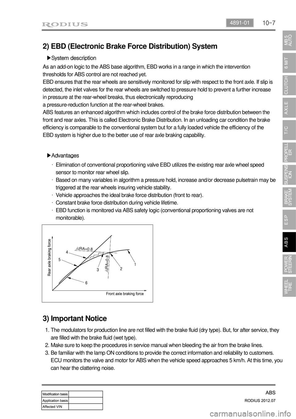
As an add-on logic to the ABS base algorithm, EBD works in a range in which the intervention
thresholds for ABS control are not reached yet.
EBD ensures that the rear wheels are sensitively monitored for slip with respect to the front axle. If slip is
detected, the inlet valves for the rear wheels are switched to pressure hold to prevent a further increase
in pressure at the rear-wheel breaks, thus electronically reproducing
a pressure-reduction function at the rear-wheel brakes.
ABS features an enhanced algorithm which includes control of the brake force distribution between the
front and rear axles. This is called Electronic Brake Distribution. In an unloading car condition the brake
efficiency is comparable to the conventional system but for a fully loaded vehicle the efficiency of the
EBD system is higher due to the better use of rear axle braking capability.
▶Advantages
Elimination of conventional proportioning valve EBD utilizes the existing rear axle wheel speed
sensor to monitor rear wheel slip.
Based on many variables in algorithm a pressure hold, increase and/or decrease pulsetrain may be
triggered at the rear wheels insuring vehicle stability.
Vehicle approaches the ideal brake force distribution (front to rear).
Constant brake force distribution during vehicle lifetime.
EBD function is monitored via ABS safety logic (conventional proportioning valves are not
monitorable). ·
·
·
·
·
3) Important Notice
The modulators for production line are not filled with the brake fluid (dry type). But, for after service, they
are filled with the brake fluid (wet type).
Make sure to keep the procedures in service manual when bleeding the air from the brake lines.
Be familiar with the lamp ON conditions to provide the correct information and reliability to customers.
ECU monitors the valve and motor for ABS when the vehicle speed approaches 5 km/h. At this time, you
can hear the clattering noise. 1.
2.
3.