Page 277 of 715

09-51451-01
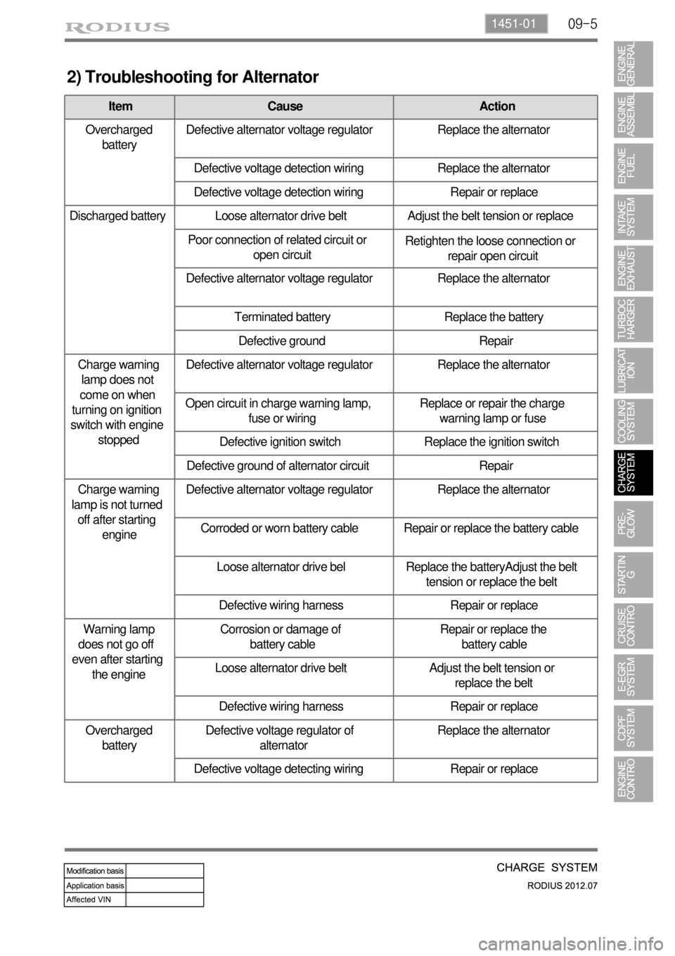
2) Troubleshooting for Alternator
Item Cause Action
Overcharged
batteryDefective alternator voltage regulator Replace the alternator
Defective voltage detection wiring Replace the alternator
Defective voltage detection wiring Repair or replace
Discharged battery Loose alternator drive belt Adjust the belt tension or replace
Poor connection of related circuit or
open circuitRetighten the loose connection or
repair open circuit
Defective alternator voltage regulator Replace the alternator
Terminated battery Replace the battery
Defective ground Repair
Charge warning
lamp does not
come on when
turning on ignition
switch with engine
stoppedDefective alternator voltage regulator Replace the alternator
Open circuit in charge warning lamp,
fuse or wiringReplace or repair the charge
warning lamp or fuse
Defective ignition switch Replace the ignition switch
Defective ground of alternator circuit Repair
Charge warning
lamp is not turned
off after starting
engineDefective alternator voltage regulator Replace the alternator
Corroded or worn battery cable Repair or replace the battery cable
Loose alternator drive bel Replace the batteryAdjust the belt
tension or replace the belt
Defective wiring harness Repair or replace
Warning lamp
does not go off
even after starting
the engineCorrosion or damage of
battery cableRepair or replace the
battery cable
Loose alternator drive belt Adjust the belt tension or
replace the belt
Defective wiring harness Repair or replace
Overcharged
batteryDefective voltage regulator of
alternatorReplace the alternator
Defective voltage detecting wiring Repair or replace
Page 348 of 715

15-230000-00
This is done periodically under certain operating conditions. When the resetting is finished, the new
minimum pulse value replaces the value obtained during the previous resetting. The first MDP value is
provided by the C3I. Each resetting then allows the closed loop of the MDP to be updated according to
the deviation of the injector.
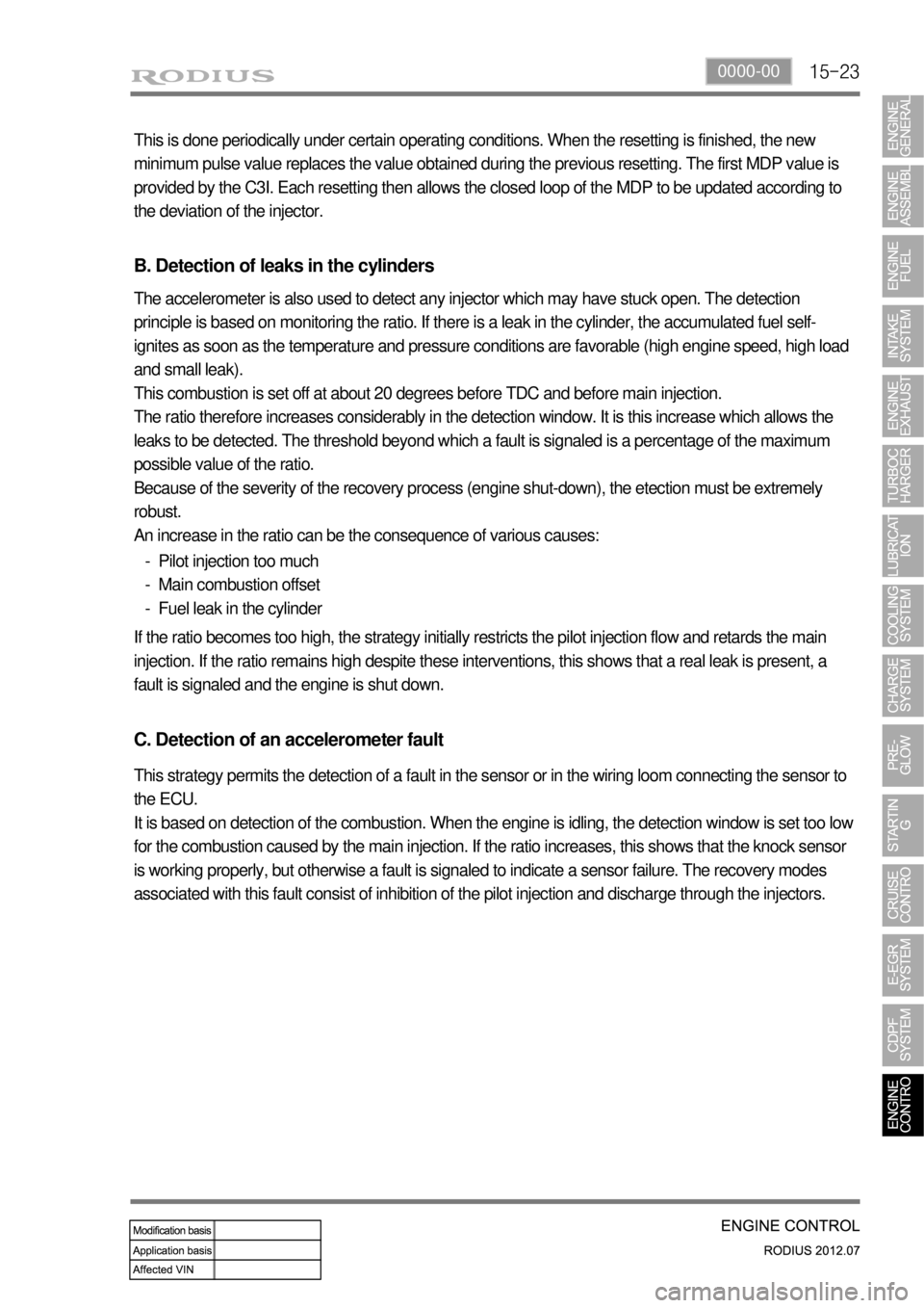
B. Detection of leaks in the cylinders
The accelerometer is also used to detect any injector which may have stuck open. The detection
principle is based on monitoring the ratio. If there is a leak in the cylinder, the accumulated fuel self-
ignites as soon as the temperature and pressure conditions are favorable (high engine speed, high load
and small leak).
This combustion is set off at about 20 degrees before TDC and before main injection.
The ratio therefore increases considerably in the detection window. It is this increase which allows the
leaks to be detected. The threshold beyond which a fault is signaled is a percentage of the maximum
possible value of the ratio.
Because of the severity of the recovery process (engine shut-down), the etection must be extremely
robust.
An increase in the ratio can be the consequence of various causes:
Pilot injection too much
Main combustion offset
Fuel leak in the cylinder -
-
-
If the ratio becomes too high, the strategy initially restricts the pilot injection flow and retards the main
injection. If the ratio remains high despite these interventions, this shows that a real leak is present, a
fault is signaled and the engine is shut down.
C. Detection of an accelerometer fault
This strategy permits the detection of a fault in the sensor or in the wiring loom connecting the sensor to
the ECU.
It is based on detection of the combustion. When the engine is idling, the detection window is set too low
for the combustion caused by the main injection. If the ratio increases, this shows that the knock sensor
is working properly, but otherwise a fault is signaled to indicate a sensor failure. The recovery modes
associated with this fault consist of inhibition of the pilot injection and discharge through the injectors.
Page 402 of 715

08-51452-01
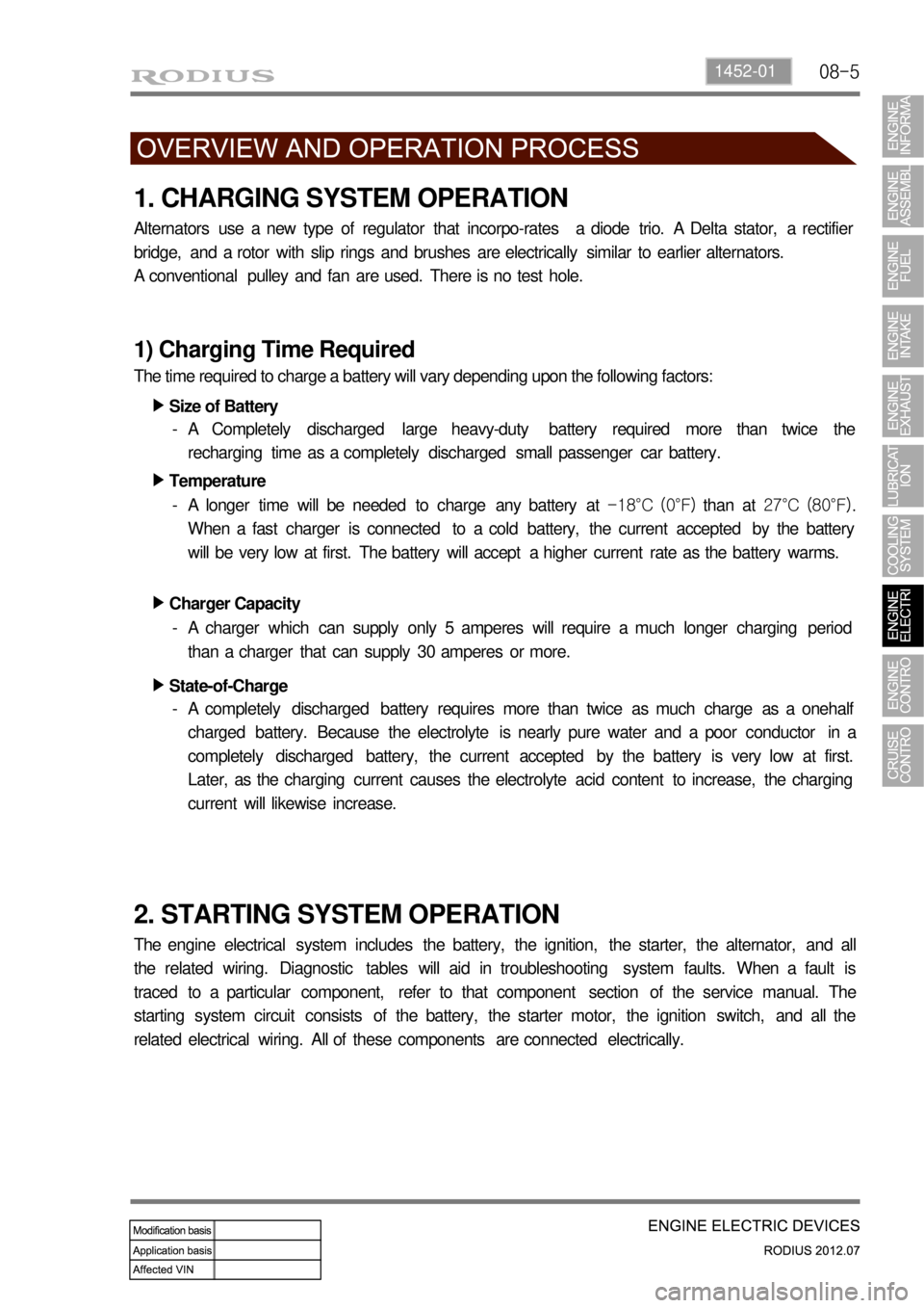
1. CHARGING SYSTEM OPERATION
Alternators use a new type of regulator that incorpo-rates a diode trio. A Delta stator, a rectifier
bridge, and a rotor with slip rings and brushes are electrically similar to earlier alternators.
A conventional pulley and fan are used. There is no test hole.
1) Charging Time Required
The time required to charge a battery will vary depending upon the following factors:
Size of Battery ▶
A Completely discharged large heavy-duty battery required more than twice the
recharging time as a completely discharged small passenger car battery. -
Temperature ▶
A longer time will be needed to charge any battery at -18°C (0°F) than at 27°C (80°F).
When a fast charger is connected to a cold battery, the current accepted by the battery
will be very low at first. The battery will accept a higher current rate as the battery warms. -
Charger Capacity ▶
A charger which can supply only 5 amperes will require a much longer charging period
than a charger that can supply 30 amperes or more. -
State-of-Charge ▶
A completely discharged battery requires more than twice as much charge as a onehalf
charged battery. Because the electrolyte is nearly pure water and a poor conductor in a
completely discharged battery, the current accepted by the battery is very low at first.
Later, as the charging current causes the electrolyte acid content to increase, the charging
current will likewise increase. -
2. STARTING SYSTEM OPERATION
The engine electrical system includes the battery, the ignition, the starter, the alternator, and all
the related wiring. Diagnostic tables will aid in troubleshooting system faults. When a fault is
traced to a particular component, refer to that component section of the service manual. The
starting system circuit consists of the battery, the starter motor, the ignition switch, and all the
related electrical wiring. All of these components are connected electrically.
Page 418 of 715
01-4
Make sure a connector is connected
securely. Loose connection results in
malfunction. -
When inspecting the airbag system, make
sure to use a diagnostic device, not a
circuit tester.When disconnecting a connector equipped
with a lock, press it down to the direction in
the below figure. -
When checking voltage or continuity of the
connector terminal with a circuit tester,
connect the tester probe to the terminal at
the harness side. For a sealed type
connector, connect the probe to the
terminal through the hole in the rubber cap
of the wiring. Take care not to damage the
insulation of the wires. Insert the probe until
it contacts the terminal completely. -
Page 419 of 715
01-58410-02
2. CHECKING CABLES AND WIRES
Check for loose connection or rust.
Check terminals and wires for corrosion due to electrolyte leakage.
Check terminals and wires for open circuit.
Check the wire insulation and coat for damage, cracks or deterioration.
Check if the conductive parts of the terminals do not contact with vehicle body or other metal
parts.
Check that the grounding part has continuity with mounting bolts and vehicle body.
Check that wires are properly routed.
Make sure that wires are securely fixed to avoid contact with sharp body parts and
hightemperature
parts, such as the exhaust manifold and exhaust pipes.
The rotating parts, such as fan pulley and fan belt, perturbative parts and wiring should be
secured tightly at regular intervals.
Secure the wiring between the fixed parts, such as the vehicle body, and vibrating parts, such
as the engine, after slackening it slightly to prevent it from being damaged. -
-
-
-
-
-
-
-
-
Page 552 of 715
02-14
3166-00 Extension housing ▶
Lever assembly - Semi remote
Lever - Shift
Boot - Rubber
Ring - Retainer
O-ring
Bearing
Shim
Arm - Control
Damper assembly
Rod assembly
Bushing assembly - TGS mounting
Pin - TGS mounting
Pin - Spring
Pin - Spring
Adapter - Case 1.
3.
4.
5.
6.
7.
8.
9.
10.
13.
14.
15.
16.
17.
20.Bolt - Flange (42.1 ~ 53.9 Nm)
Seal - Oil
Seal - Oil
Pin - Dowel
Switch - Neutral (29.4 ~ 34.3 Nm)
Gasket
Bolt - Interlock (14.7 ~ 21.5 Nm)
Pin - Detent
Switch - Backup lamp (29.4 ~ 34.3
Nm)
Bolt - Fork hinge (53.9 ~ 67.6 Nm)
Bearing - Poppet ball (29.4 ~ 41.1
Nm)
Bolt - Guide (14.7 ~ 21.5 Nm)
Bolt (2.9 ~ 4.9 Nm)
Bracket - Wiring 21.
22.
23.
24.
25.
26.
27.
28.
29.
30.
31.
32.
33.
34.
Page 657 of 715
01-2
Front air conditioner module assembly - inside instrument panel
Compressor - engine rightAQS/Air source selection
switch
Sun load sensor - instrument
panel upper left
1. SYSTEM LAYOUT AND COMPONENTS
Type Air cindotioner controller
FATC
Manual air
conditioner
It change sun load coming through
front windshield into current to input to
FATC controller. *
Air mix door
actuator
PTC (If equipped)
Duct temperature
sensor
Mode door
actuator
Air conditioner wiring
Thermo AMP
Air source door
actuator
Air conditioner
filter
Bloewr motor
Blower high speed relayPower transistor
Page 661 of 715
01-6
2) AIR CONDITIONER MODULE WIRING AND LAYOUT
(1) Front Air Conditioner Module
Air source selection
door actuator
Air conditioner
filterEvaporator
Blower motor
Blower high
speed relay
Heater core
Wiring layout
Components