Page 160 of 715
02-30000-00
Cylinder block Piston protrusion 0.475 to 0.745mm -
Piston ring TOP ring end gap 0.20 to 0.35 mm -
2nd ring end gap 0.35 to 0.50 mm -
3rd ring end gap 0.2 to 0.40 mm -
Offset 0.3mm -
Head gasket Piston protrusion 0.475 to 0.540 1.2t -
0.541 to 0.649 1.3t -
0.650 to 0.745 1.4t -
1. ENGINE ASSEMBLY
Unit Description Specification Remark
Cylinder head Height 131.9 to 132.1 mm -
Flatness below 0.1 mm -
Valve protrusion Intake valve 0.6 to 1.0 mm -
Exhaust valve 0.6 to 1.0 mm -
Flatness on
manifold sideIntake manifold 0.08 mm -
Exhaust manifold 0.08 mm -
Connecting rod End play 0.5 to 0.31 mm -
Camshaft Axial end play Intake 0.1 to 0.35 mm -
Exhaust 0.1 to 0.35 mm -
Camshaft
position sensorDistance between Camshaft position
sensor and sprocket0.20 to 1.80 mm -
Page 161 of 715
02-4
2. TIGHTENING TORQUE
Component SizeBolt
QuantitySpecified torque
(Nm)Remark
(Total torque)
Main bearing capM12×82 10 55±5Nm,
180˚ Not re-usable
Connecting rod capM9×52 8 40±5Nm,
90˚+10˚ 50 to 80 Nm
Crankshaft rear sealM6×20 6 10±1Nm -
Oil pump M8x35 3 25±2.5Nm -
Drive plateM10×22 8 45±5Nm,
90˚+10˚ 60 to 100 Nm
Isolation damper center
boltM18x50 1 200±20Nm,
180˚+20˚660 to 720 Nm
Not re-usable
Oil panM6×20 18 10±1Nm -
M6×35 2 10±1Nm -
M6×85 2 10±1Nm -
M6×120 2 10±1Nm -
M8×40 2 25±2.5Nm -
HP pump main nutM14×1.5-8-1 1 65±5Nm -
HP pump bolt M8x30 3 25±2.5Nm -
Cylinder headM13×150 12 85Nm
270°±10° -
Camshaft capM6×30 16 10±1Nm -
M8×60 4 25±2.5Nm -
Exhaust stud bolt 10 15±1.5Nm -
Exhaust sprocket boltM11×40 1 30±3Nm -
Chain tensioner screw
plugM38×1.5 1 25±2.5Nm -
Coolant temperature
sensor1 20±2.0Nm
-
Auto tensionerM8×30(LOW) 1 25±2.5Nm -
M10×75(Upper)1 55±5.5Nm -
Coolant pumpM6×50 7 10±1.0Nm -
Page 162 of 715
02-50000-00
Component SizeBolt
QuantitySpecified torque
(Nm)Remark
(Total torque)
Hot water inlet pipeM6×12210±1Nm-
AlternatorM10×901(lower) 25±2.5Nm-
M10×1161(upper) 46±4.6Nm-
A/C compressorM8×85425±2.5Nm-
A/C bracketM6×25410±1Nm-
Intake manifoldM8×35225±2.5Nm-
M8×110625±2.5Nm-
Oil filter moduleM8×40625±2.5Nm-
M8×20125±2.5Nm-
M8×140225±2.5Nm-
Knock sensorM8×28220±5Nm-
Cam position sensorM8×141 10~14Nm -
T-MAP pressure
sensorM6×20110±1Nm-
Exhaust manifold M8 1040±4Nm-
Turbocharger M8 325±2.5Nm-
T/C support bolt 125±2.5Nm-
T/C support nut M8 125±2.5Nm-
T/C oil supply pipe M6(block side) 110±1.0Nm-
M6(turbo side) 117±2.0Nm-
T/C oil return pipeM6×16
(turbo side)210±1Nm-
M6×16
(block side)210±1Nm-
EGR valveM8×22325±2.5Nm-
EGR pipe bolt
(Intake side)M8×16210±1.0Nm-
EGR pipe bolt
(EGR cooler side)M8×16225±2.5Nm-
Idle pulley/Tensioner
pulley145±4.5Nm -
Page 163 of 715
02-6
Cylinder head coverM6×352110±1Nm-
Oil gauge tubeM6×16110±1Nm-
Oil filter cap 125±2.5Nm-
Fuel railM8×25225±2.5Nm-
Injector clamp boltM6×4429±1.0Nm
130˚±10˚-
High pressure pipe
(between HP pump and
fuel rail)M17 130±3Nm-
High pressure pipe
(between fuel rail and
injector)M17 430±3Nm-
Crank position sensorM5×1418±0.4Nm-
Main wiringM6×16510±1Nm-
Intake ductM8×25325±2.5Nm-
Power steering pumpM8×100325±2.5Nm-
Cylinder head front
coverM6×10510±1Nm-
Ladder frame M8x16 530±3Nm-
Component SizeBolt
QuantitySpecified torque
(Nm)Remark
(Total torque)
Glow plug M5 420±2Nm-
Vacuum pumpM8×25310±1Nm-
Timing gear case coverM6×40710±1Nm-
M6×45110±1Nm-
M6×50310±1Nm-
Page 164 of 715

02-70000-00
3. CHECK AND INSPECTION
1) Cylinder
(1) Compression pressure test
Specified value ▶
Compression ratio16.5 : 1
Test conditionat normal operating temperature (80˚C)
Compression pressur
eStandard32 bar
Minimum18 bar
Differential limit between cylindersMaximum 3 bar
The compression pressure test is to check the conditions of internal components (piston, piston
ring, intake and exhaust vale, cylinder head gasket). This test provides current engine operating
status.
Measurement ▶
<007e0088009900940047009b008f008c0047008c0095008e00900095008c0047009c00970047009b00960047009500960099009400880093004700960097008c00990088009b00900095008e0047009b008c00940097008c00990088009b009c0099008c00
47004f005f005700b6006a00500055>
Disconnect the fuel rail pressure sensor connector to cut off the fuel injection.
Remove the air cleaner duct and glow plugs. -
-
-
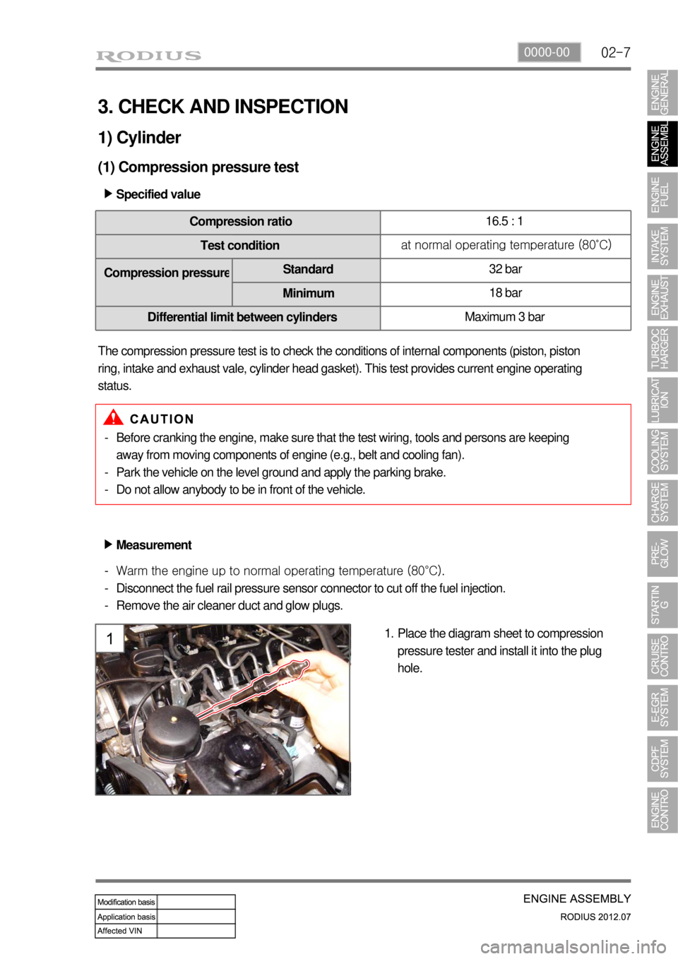
Place the diagram sheet to compression
pressure tester and install it into the plug
hole. 1. Before cranking the engine, make sure that the test wiring, tools and persons are keeping
away from moving components of engine (e.g., belt and cooling fan).
Park the vehicle on the level ground and apply the parking brake.
Do not allow anybody to be in front of the vehicle. -
-
-
Page 181 of 715
02-24
Vacuum pump driveHP pump drive gear
Cylinder head gasket
Camshaft position sensor
Components ▶
Cylinder head
Cylinder head contains cam position sensor, vacuum pump, intake manifold, exhaust manifold and
valve assembly. Vacuum pump and the high pressure (HP) pump are driven by Camshaft and valves
are install in vertical direction. This enables the compact layout in cylinder head assembly.
6. CYLINDER HEAD
Finger follower & HLACamshaft sprocketIntake/exhaust Camshafts
Page 204 of 715
02-470000-00
4) Cylinder Block
(1) Overview
The major dimensions in D20DTR are similar to
D20DTR engine. It has two mounting
bosses for knock sensor and meets the
requirements for EURO5 regulation.
(2) Layout
Right sideCylindrical pin
Expansion plug
Screw plug
Page 216 of 715
03-12
(5) High Pressure System Pressure Test
Fuel rail pressure test ▶
Disconnect the pressure sensor connector
(A) and IMV connector (B) from the fuel
rail. 1.
Connect the pressure tester to the fuel rail
pressure sensor connector. 2.
Crank the engine 2 times for 5 seconds. 3.
Read the highest pressure value
displayed on the tester display.
If the highest pressure value is 1,050 bar
or less, refer to the section "Fuel System
Check Process". -
-