Page 336 of 715

15-110000-00
2) ECU Control
(1) Function
a. ECU Function
ECU receives and analyzes signals from various sensors and then modifies those signals into
permissible voltage levels and analyzes to control respective actuators.
ECU microprocessor calculates injection period and injection timing proper for engine piston speed and
crankshaft angle based on input data and stored specific map to control the engine power and emission
gas.
Output signal of the ECU microprocessor drives pressure control valve to control the rail pressure and
activates injector solenoid valve to control the fuel injection period and injection timing; so controls
various actuators in response to engine changes. Auxiliary function of ECU has adopted to reduce
emission gas, improve fuel economy and enhance safety, comforts and conveniences. For example,
there are EGR, booster pressure control, autocruise (export only) and immobilizer and adopted CAN
communication to exchange data among electrical systems (automatic T/M and brake system) in the
vehicle fluently. And Scanner can be used to diagnose vehicle status and defectives.
<00760097008c00990088009b00900095008e0047009b008c00940097008c00990088009b009c0099008c0047009900880095008e008c00470096008d0047006c006a007c00470090009a0047009500960099009400880093009300a000470054005b005700
47009b009600470052005f005c00b6006a004700880095008b> protected from factors like oil,
water and electromagnetism and there should be no mechanical shocks.
To control the fuel volume precisely under repeated injections, high current should be applied instantly
so there is injector drive circuit in the ECU to generate necessary current during injector drive stages.
Current control circuit divides current applying time (injection time) into full-in-current-phase and hold-
current-phase and then the injectors should work very correctly under every working condition.
b. Control Function
Controls by operating stages
To make optimum combustion under every operating stage, ECU should calculate proper injection
volume in each stage by considering various factors.
Starting injection volume control
During initial starting, injecting fuel volume will be calculated by function of temperature and engine
cranking speed. Starting injection continues from when the ignition switch is turned to ignition
position to till the engine reaches to allowable minimum speed.
Driving mode control
If the vehicle runs normally, fuel injection volume will be calculated by accelerator pedal travel and
engine rpm and the drive map will be used to match the drivers inputs with optimum engine power. -
-
-
Page 363 of 715

15-38
Relay box
A/C
compressorHFM (intake air
temperature)Cooling fan
module
MB 5 A/T (ATF
temperature)Coolant
temperature
sensor
(12) Cooling fan control
A. Overview of cooling fan and A/C compressor
The cooling system maintains the engine temperature at an efficient level during all engine operating
conditions. The water pump draws the coolant from the radiator. The coolant then circulates through
water jackets in the engine block, the intake manifold, and the cylinder head. When the coolant reaches
the operating temperature of the thermostat, the thermostat opens. The coolant then goes back to the
radiator where it cools. The heat from automatic transmission is also cooled down through the radiator
by circulating the oil through the oil pump. ECU controls the electric cooling fans with three cooling fan
relays to improve the engine torque and air conditioning performance.
For detailed information, refer to Chapter "Air Conditioning System".
B. Components
D20DTR ECU
Refrigerant
Page 374 of 715

15-490000-00
E. Cautions
Use only specified Engine Oil (approved by MB Sheet 229.51) for CDPF. -
Use only specified engine oil (Low Ash Oil) ▶
The vehicle equipped with CDPF should use specific engine oil to improve the engine performance
and fuel economy, and ensure the service life of CDPF. -
Issue with normal engine oil ▶
Sulfur, one of the contents of engine oil is burned and generates soot that is not regenerated by the
DPF. This remains on the filter as ashes and keeps accumulating. Eventually, this ashes will block
the filter. -
Benefit for specified engine oil ▶
Minimized the sulfur content of engine oil which reduces the service life.
Improved fuel economy and emission level of CO2 with high performance and low viscosity.
Increased service life of engine oil with high resistance to temperature. -
-
-
Problems when using unspecified engine oil ▶
The service life of filter may be reduced by 30% or more by the ashes accumulated on the filter.
The fuel economy may be reduced because of engine rolling resistance, frequent regeneration of
DPF. -
-
These problems are also caused by oil with high sulfur content, such as tax exemption oil and
heating oil, etc. *
Page 594 of 715
08-34850-03
Brake oil Grade DOT 4
Service interval Replace every 2 years
1. SPECIFICATIONS
Description Specification
Front brake Type Ventilated disc
Rear brake Type Ventilated disc
Master cylinder Type Step feed bore tandem, double cylinder
Brake booster Type Tandem type(integrated level sensor)
Operating type Foot operated type
Page 646 of 715

11-8
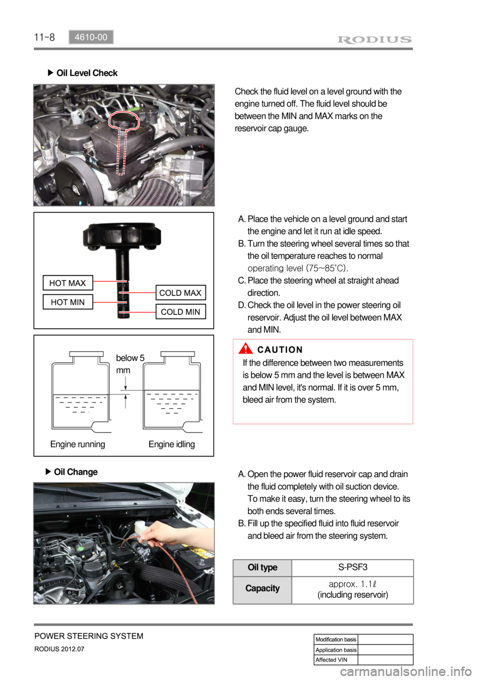
Oil Level Check ▶
Check the fluid level on a level ground with the
engine turned off. The fluid level should be
between the MIN and MAX marks on the
reservoir cap gauge.
Place the vehicle on a level ground and start
the engine and let it run at idle speed.
Turn the steering wheel several times so that
the oil temperature reaches to normal
operating level (75~85˚C).
Place the steering wheel at straight ahead
direction.
Check the oil level in the power steering oil
reservoir. Adjust the oil level between MAX
and MIN. A.
B.
C.
D.
Oil Change ▶
If the difference between two measurements
is below 5 mm and the level is between MAX
and MIN level, it's normal. If it is over 5 mm,
bleed air from the system.
Open the power fluid reservoir cap and drain
the fluid completely with oil suction device.
To make it easy, turn the steering wheel to its
both ends several times.
Fill up the specified fluid into fluid reservoir
and bleed air from the steering system. A.
B.
Oil typeS-PSF3
Capacityapprox. 1.1ℓ
(including reservoir)
below 5
mm
Engine running Engine idling
Page 647 of 715
11-94610-00
Air Bleeding ▶
The air bleeding should be done after servicing the
power steering system and when the difference
between two measurements (cooled and normal
temperature) is prominent.
Normal AbnormalLift up the vehicle very carefully.
Turn the steering wheel to its both ends
several times and add the oil up to MAX line
in the steering oil reservoir.
Periodically crank the starting motor and turn
the steering wheel to its both ends without
any interruption.
Check the oil level again. If the oil level is
fluctuated, repeat the procedures from step 3
to step 5.
Start the engine.
Turn the steering wheel to its both ends until
any bubble can be found in the steering oil
reservoir.
Perform the test drive and check the steering
wheel for normal operation and noise.
If the oil level abruptly goes up, bleed the air
from the system again. A.
B.
C.
D.
E.
F.
G.
H.
If the air bleeding is not properly performed,
the life span of the power steering pump may
be shortened. -
Page 648 of 715
11-10
Oil Pump Pressure Check ▶
Check the oil pump pressure to locate any defect
in oil pump.
Before checking the pressure, check the oil
level and belt tension. Prepare the empty
container to collect the spilled oil during the
service.
Unscrew the pressure line fitting in power
steering pump.
Install the pressure gauge between the
power steering pump and the power steering
oil pressure line.
Place the shift lever to neutral position. Apply
the parking brake.
Open the valve in pressure gauge. Start the
engine and let it run at idle speed.
Turn the steering wheel several times so that
the oil temperature reaches to normal
operating level. A.
B.
C.
D.
E.
Fully close the valve in pressure gauge and
measure the oil pressure. F.
To prevent internal damage, do not close the
gauge valve over 10 seconds.
Keep the oil temperature at proper range. -
-
Relief pressure90 ± 3 bar