Page 268 of 600
Name SizeNumbers of
fastenerTightening
torque (Nm)Note (total
tightening
torque)
Idler pulley/tensioner
pulley1
-
Glow plug M5 4
-
Vacuum pump
3 -
Timing gear case cover
7 -
1 -
3 -
Cylinder head cover
21 -
Oil dipstick gauge cover
1 -
Oil filter cap 1
-
Fuel rail
2 -
Injector clamp bolt
2 -
High pressure pipe
(between high pressure
pump and fuel rail
assembly)M17 1
-
High pressure pipe
(between fuel rail
assembly and injector)M17 4
-
Crankshaft position
sensor
1 -
Main wiring
5 -
Intake duct
3 -
Power steering pump
3 -
Cylinder head front cover
5 -
Page 273 of 600
Component SizeBolt
QuantitySpecified torque
(Nm)Remark
(Total torque)
Glow plug M5 4
-
Vacuum pump
3 -
Timing gear case cover
3 -
7 -
1 -
3 -
Cylinder head cover
21 -
Oil gauge tube
1 -
Oil filter cap 1
-
Fuel rail
2 -
Injector clamp bolt
2 -
High pressure pipe
(between HP pump and
fuel rail)M17 1
-
High pressure pipe
(between fuel rail and
injector)M17 4
-
Crank position sensor
1 -
Main wiring
5 -
Intake duct M8x25 4
-
Power steering pump
3 -
Cylinder head front cover
5 -
Ladder frame
5 -
Oil pump
3 -
Page 275 of 600
(2) Cylinder pressure leakage test
If the measured value of the compression pressure test is not within the specifications, perform the
cylinder pressure leakage test.Specified value
Perform this test in the sequence of firing order.
Do not test the cylinder pressure leakage with wet type test procedure. (do not inject the engine oil
into the combustion chamber) -
-
Test condition: normal engine operating Specified value
Whole engine below 25%
at valve and cylinder head gasket below 10%
at piston ring below 20%
Crank the engine for approx. 10 seconds by
using the start motor. 2.
Record the test result and measure the
compression pressure of other cylinders with
same manner. 3.
If the measured value is out of specified
value, perform the cylinder pressure leakage
test. 4.
Page 285 of 600
Brake booster and naster
cylinderVacuum pump
Pump capacity: 210 cc/rev
Camshaft speed: 375 to 3,000 rpm
Lubrication temperature: -40 to
Oil: 5W30
Drive type: Driven by exhaust
Camshaft sprocket
2. VACUUM PUMP
Vacuum pump generates the vacuum pressure and supplies it to EGR cooler bypass solenoid. This
pump is single vane type and displacement is 210 cc/rev. The lubrication oil is supplied through the hole
in hollow shaft.
Components
EGR cooler bypass valve
This valve is controlled by ECU.
When the engine is cooled, the
exhaust gas goes to combustion
chamber without passing through
EGR cooler because the valve is
closed by vacuum pressure.
Page 297 of 600

(2) Layout
Chain upper bush
Type: single bush
Chains:112 EA
Tensioner rail
Installed between exhaust
Camshaft sprocket and
crankshaft sprocket
Hydraulic tensioner
Contains tensioner housing
plug, spring and check valve,
and operated by hydraulic
pressure
Crankshaft sprocket
Teeth: 21 EA
Oil pump sprocket
Teeth: 33 EA
Chain lower bush
Chain type: single bush
Chains: 60 EA
Mechanical type tensioner
Operated by internal spring
Clamping rail
Installed between exhaust
Camshaft sprocket and
crankshaft sprocket
Exhaust camshaft
sprocket
Teeth: 42 EA
1) Chain Drive
(1) Overview
The drive chain is single chain drive system with simple design and variable performance, and it utilizes
the hydraulic tensioner to reduce the wave impact generated by the chain. This chain is light weight and
has high durability through single bush chain. Shoulder bolts are used for better NHV.
7. CHAIN AND GEAR DRIVE SYSTEM
D20DTR engine uses single stage chain drive system. Timing chain drives the exhaust side and gear
drive the intake side. Timing chain is single bush type. Upper chain drives HP pump connected to intake
Camshaft by driving exhaust cam shift sprocke, and lower chain drives oil pump to lubricate the engine.
Page 318 of 600
2. MAINTENANCE AND INSPECTION
1) Maintenance Procedures for DI Engine Fuel System
Always keep the workshop and lift clean (especially, from dust).
Always keep the tools clean (from oil or foreign materials).
Wear a clean vinyl apron to prevent the fuzz, dust and foreign materials from getting into fuel system.
Wash your hands and do not wear working gloves. 1.
2.
3.
Follow the below procedures before starting service works for fuel system.
If the problem is from HP pump, fuel supply line or injector, prepare the clean special tools and sealing
caps to perform the diagnosis for DI engine fuel system in this manual. At this point, thoroughly clean
the related area in engine compartment. 4.
Clean the engine compartment before starting service works.
Tool kit for high pressure lineTook kit for low pressure line
Page 334 of 600

(2) Di engine and its expected problems and remedies can be caused by
water in fuel
System supplement against paraffin separation
In case of Diesel fuel, paraffin, one of the elements, can be separated from fuel during winter and then
can stick on the fuel filter blocking fuel flow and causing difficult starting finally. Oil companies supply
summer fuel and winter fuel by differentiating mixing ratio of kerosene and other elements by region and
season. However, above phenomenon can be happened if stations have poor facilities or sell improper
fuel for the season. In case of DI engine, purity of fuel is very important factor to keep internal
preciseness of HP pump and injector.
Accordingly, more dense mesh than conventional fuel filter is used. To prevent fuel filter internal clogging
due to paraffin separation, SYMC is using fuel line that high pressure and temperature fuel injected by
injector returns through fuel filter to have an effect of built-in heater (see fuel system).
System supplement and remedy against water in fuel
As mentioned above, some gas stations supply fuel with excessive than specified water. In the
conventional IDI engine, excessive water in the fuel only causes dropping engine power or engine
hunting. However, fuel system in the DI engine consists of precise components so water in the fuel can
cause malfunctions of HP pump due to poor lubrication of pump caused by poor coating film during high
speed pumping and bacterization (under long period parking). To prevent problems can be caused by
excessive water in fuel, water separator is installed inside of fuel filter. When fuel is passing filter, water
that has relatively bigger specific gravity is accumulated on the bottom of the filter.
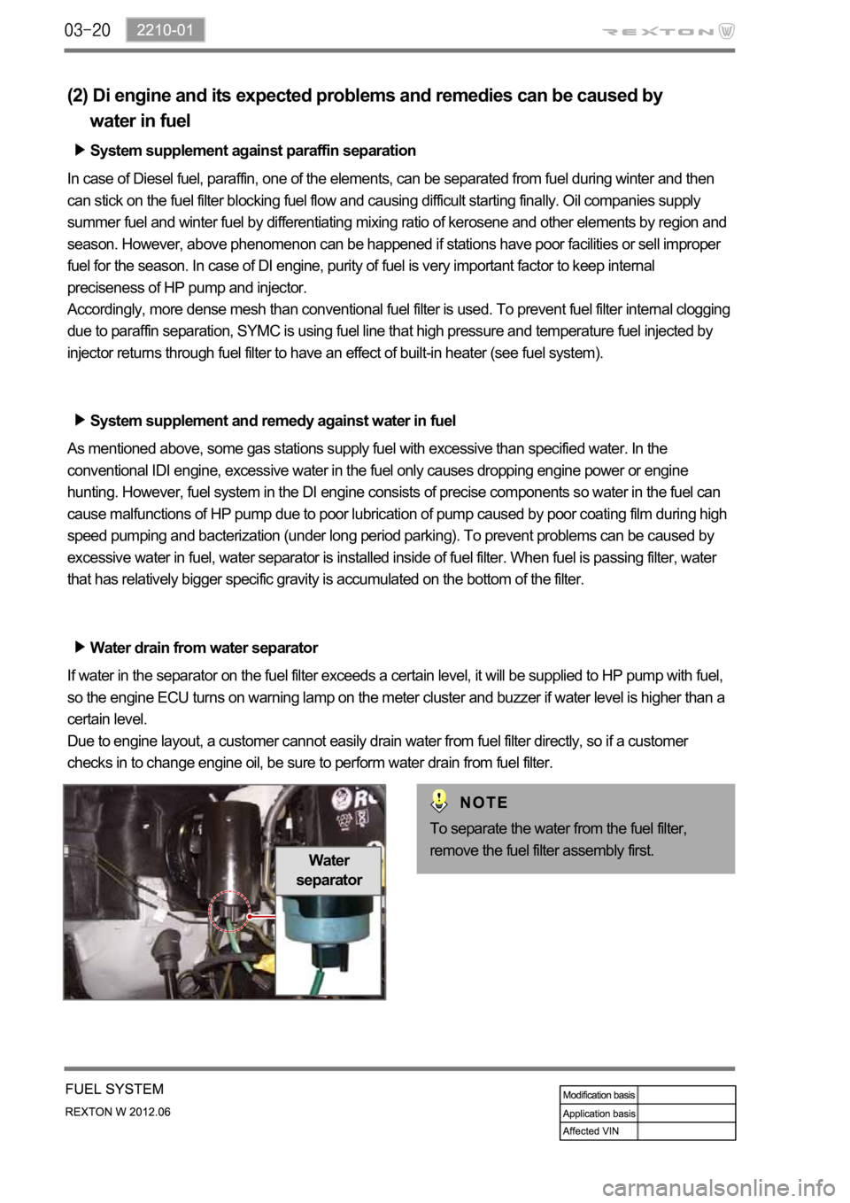
Water drain from water separator
If water in the separator on the fuel filter exceeds a certain level, it will be supplied to HP pump with fuel,
so the engine ECU turns on warning lamp on the meter cluster and buzzer if water level is higher than a
certain level.
Due to engine layout, a customer cannot easily drain water from fuel filter directly, so if a customer
checks in to change engine oil, be sure to perform water drain from fuel filter.
Water
separator
To separate the water from the fuel filter,
remove the fuel filter assembly first.
Page 342 of 600

2. INSPECTION
1) Troubleshooting
When Abnormal Noises are Heard from the Engine Room
For the vehicle equipped with DI engine, if a learning noise occurs in each range or other noises
occur, the major cause of it is a faulty turbocharger assembly. But an interference issue, poor
tightness or loose in the intake and exhaust system also can cause those noises. This is mainly
because the operator didn't follow the instruction exactly when reconnecting the intake hoses and
pipes which were disconnected to check the system or replace the air cleaner. If the intake system is
free of any faults, check the EGR and PCV oil separator connected to the intake system.
The figure may be different from the actual engine. Therefore, read thoroughly below before replacing
the parts.
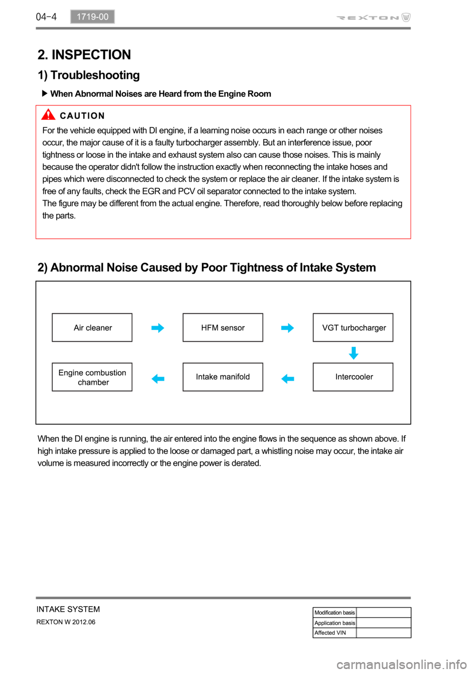
2) Abnormal Noise Caused by Poor Tightness of Intake System
When the DI engine is running, the air entered into the engine flows in the sequence as shown above. If
high intake pressure is applied to the loose or damaged part, a whistling noise may occur, the intake air
volume is measured incorrectly or the engine power is derated.