Page 565 of 828

01-213680-01
Pressure Modulation ▶
To provide a higher level of shift comfort and durability, the hydraulic pressure in the shift related
friction elements of the transmission must be matched accurately to the input torque to
transmission. This hydraulic pressure is composed of a hydraulically pre-set basic pressure and a
control pressure which is set by one of the variable bleed solenoids.
The transmission input torque can be directly calculated from the following operating parameters:
engine torque signals
engine speed or any signal transmitted from ECU through CAN lines
converter slip -
-
-
Separate pressure characteristics for each gear change make it possible to adapt precisely to the
particular shift operation.
5) Shift Mode Selection by TCU
The driver can select Standard (S) or Winter mode (W) with the mode switch. TCU automatically
changes the shift mode according to the transmission oil temperature, uphill or downhill gradient,
and altitude to keep the good driving conditions.
Standard Mode (S) ▶
Uphii and Downhill Mode ▶
Altitude Mode ▶ Standard Mode is selected when setting the mode switch in Standard (S) position with the gear
<009a008c0093008c008a009b00470093008c009d008c0099004700900095004702c8006b02c9004700880095008b0047009b008f008c0047009b009900880095009a00940090009a009a00900096009500470096009000930047009b008c00940097008c00
990088009b009c0099008c0047009000950047009500960099>mal operating range. Proper shift
timing provides the optimized fuel economy and good driving conditions.
In this mode, the operating points of torque converter lock-up clutch and the shifting points are
adjusted according to the vehicle weight.
In this mode, the shifting points are automatically adjusted according to the altitude to compensate
the engine torque changes due to barometric pressure and temperature.
Page 566 of 828

01-22
Winter Mode (W) ▶
Low Range Driving Mode ▶
Warm Up Mode ▶ When the Winter mode is selected, the second gear is engaged to start off the vehicle easily to
prevent wheel spin on slippery surfaces and WINTER mode indicator comes ON. The first gear is
not available in this mode.
When the vehicle is in 4L driving mode, the transmission uses a different shift mode to optimize
the low range driving. Similar to Winter mode, the first gear is not available.
This mode is normally used when the transmission oil temperature is below 20°C.
<007b008f008c0047009b009600990098009c008c0047008a00960095009d008c0099009b008c00990047008a0088009500950096009b00470089008c004700930096008a0092008c008b0054009c009700470089008c00930096009e00470059005700b600
6a0047009b00960047009700990096009d0090008b008c0047>the warming up process of
transmission.
Hot Mode ▶
<0070008d0047009b008f008c0047009b009900880095009a00940090009a009a00900096009500470096009000930047009b008c00940097008c00990088009b009c0099008c00470090009a00470089008c009b009e008c008c0095004700580058005700
b6006a004700880095008b00470058005b005c00b6006a0053> the system provides the cooling
and reduces the load to the transmission. This is called Hot Mode.
Above 110°C:
Above 130°C:
Above 145°C: -
-
-
In Hot Mode, any of shift mode is not available.
Cruise Control ▶
When the cruise control is activated, the engine ECU requests the downshift to increase the
engine brake effect.PWM fan ON
the engine torque is reduced and WINTER indicator is blinking
the transmission is held in Neutral (N) gear until the oil temperature falls
below 120°C (Final protection)
Page 569 of 828
01-253680-01
1) Power Flow - Manual (M Position)
Functioning elements ▶
Control ▶C2 applied, FSG (Forward Sun Gear)
driven
B2 applied to hold Rear Planet Carrier
stationary
Provides engine breake effect -
-
-
S1 ON, C1 shift valve moved to the left end, C1 clutch not engaged
S1 ON, B2 shift valve moved to the left end, B2 band operated (S7 should be ON)
C2 shift valve open (S2 OFF), C2 clutch engaged by drive oil
Drive oil (for C2 clutch engagement) is regulated by VBS S6 -
-
-
-
Connecting Components ▶
Gear
ratioON / OFF solenoids Variable pressure sol. valve-VBS
S1 S2 S3 S4 S5(A) S6(A) S7(A) S8(A) S9(A) S10(A)
3.53 ON 1 0 1 0-1
Gear
ratioEngaged element
C1 C2 C3 B1 B2 OWC Lock-up
clutch
AO AI R AO AI
3.53 ON ON ON
Power Flow Diagram ▶
Manual 1st gear is not engaged even when
moving the manual valve to a certain position.
This gear state is obtained electronically by
solenoids S1 and S7.
Page 623 of 828
04-8
3. DUAL MASS FLYWHEEL (DMF)
The dual mass flywheel (DMF) is of having a mass divided into two halves.
While one mass is connected to the engine crankshaft, which is affected by the mass moment of
inertia of the engine, the other mass is affected by one of the transmission.
The divided dual masses are connected to the coil spring and damping system internally.
The DMF has the following benefits: ▶
Reducing fuel consumption by lowering engine speed
Reducing rattling noise and vehicle vibration in all driving ranges
Reducing synchronization wear
Facilitating gear change
Protecting power train parts by preventing excessive load from being delivered -
-
-
-
-
Primary flywheel
Secondary flywheel
Arc damper spring
Torque limiter
Ring gear 1.
2.
3.
4.
5.
Page 646 of 828

08-10
2. FRONT SUSPENSION (DOUBLE WISHBONE)
Advantage ▶
The advantage of a double wishbone suspension is that it is fairly easy to work out the effect
of moving each joint, so the kinematics of the suspension can be tuned easily and wheel
motion can be optimized.
It is also easy to work out the loads that different parts will be subjected to which allows more
optimized lightweight parts to be designed.
They also provide increasing negative camber gain all the way to full jounce travel unlike the
MacPherson strut which provides negative camber gain only at the beginning of jounce travel
and then reverses into positive camber gain at high jounce amounts. 1.
2.
3.
Disadvantage ▶
The disadvantage is that it is slightly more complex than other systems like a MacPherson strut.
Due to the increased number of components within the suspension setup it takes much longer to
service and is heavier than an equivalent MacPherson design. 1.
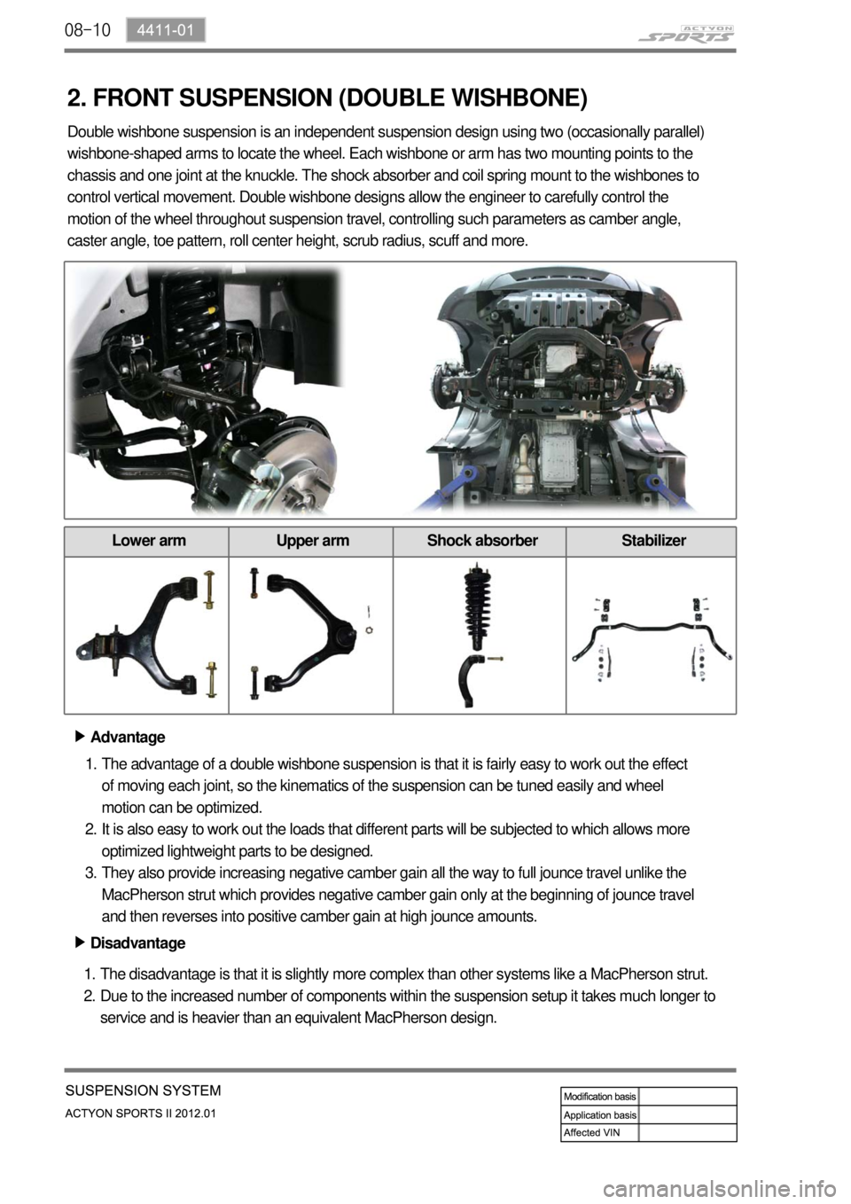
2. Double wishbone suspension is an independent suspension design using two (occasionally parallel)
wishbone-shaped arms to locate the wheel. Each wishbone or arm has two mounting points to the
chassis and one joint at the knuckle. The shock absorber and coil spring mount to the wishbones to
control vertical movement. Double wishbone designs allow the engineer to carefully control the
motion of the wheel throughout suspension travel, controlling such parameters as camber angle,
caster angle, toe pattern, roll center height, scrub radius, scuff and more.
Lower arm Upper arm Shock absorber Stabilizer
Page 661 of 828
09-134850-01
Maximum Stroke of Brake Pedal ▶
Check the brake pedal with below
procedures: -
Start the engine.
Pump the brake pedal around 3 times.
Depress the brake pedal with approx. 30
kg and measure the distance (A) between
the upper surface of pedal pad and the
lower dash panel.
If the measured value is out of the
specified value, adjust the length. 1.
2.
3.
4.
Specified value (A)150mm
5. BRAKE SYSTEM CHECK
Over the specified value
Cause Action
Worn brake pad Replace
Worn brake shoe Replace
Improper stroke of hand
brakeAdjust
Air in brake line Air bleeding
Oil leak Repair or replace
Brake booster push rod Replace or adjust
Improperly adjusted
stopper boltAdjust
Below the specified value
Cause Action
Brake booster push rod
Replace or adjust
Air in brake fluid Replace
Improperly adjusted
stopper boltAdjust
Page 709 of 828
11-8
ESP OFF switch
Located on the left side of
instrument panel.
Rear wheel speed sensor
Located on the both ends of
rear axle.Front wheel speed sensor
Located on the hub
assembly.Sensor cluster
Located at the bottom of
center fascia panel.
Steering wheel angle sensor
Located on column shaft with
contact coil.HECU assembly
Located near the brake
booster in engine
compartment and contains
the pressure sensor.
2. COMPONENTS
Page 737 of 828

12-114610-01
Oil Change ▶
Open the power fluid reservoir cap and
drain the fluid completely with oil suction
device. To make it easy, turn the steering
wheel to its both ends several times.
Fill up the specified fluid into fluid reservoir
and bleed air from the steering system. 1.
2. Oil Level Check ▶
Place the vehicle on a level ground and
start the engine and let it run at idle speed.
Turn the steering wheel several times so
that the oil temperature reaches to normal
operating level (75~85˚C).
Place the steering wheel at straight ahead
direction.
Check the oil level in the power steering oil
reservoir. Adjust the oil level between MAX
and MIN. 1.
2.
3.
4.
If the difference between two
measurements is below 5 mm and the level
is between MAX and MIN level, it's normal.
If it is over 5 mm, bleed air from the
system. Check the fluid level on a level ground with
the engine turned off. The fluid level should
be between the MIN and MAX marks on the
reservoir cap gauge.
below 5 mm
Engine idling Engine running
Oil typeATF Dexron II or III
Capacityapprox. 1ℓ (including
reservoir)