2012 SSANGYONG NEW ACTYON SPORTS battery
[x] Cancel search: batteryPage 495 of 828

04-4
1. DESCRIPTIONS OF INDICATOR DISPLAY
Tachometer
ESP indicator/warning light
Immobilizer indicator
Glow indicator
Front fog light indicator
High beam indicator
ESP OFF indicator
Seat belt reminder (driver’s seat)
Seat belt reminder (passenger’s seat)
Engine oil pressure warning light
LCD Display
Engine overheat warning light
Engine check warning light
Auto cruise indicator
Light indicator
Winter mode indicator 1.
2.
3.
4.
5.
6.
7.
8.
9.
10.
11.
12.
13.
14.
15.
16.Engine hood open warning light
Battery charge warning light
Hazard Indicator
Water separator warning light
Air bag warning light
4WD CHECK warning light
4WD LOW indicator
4WD HIGH indicator
Speedometer
Turn signal indicator
Coolant temperature gauge
Brake warning light
Door ajar warning light
ABS warning light
Fuel gauge
Low fuel level warning light 17.
18.
19.
20.
21.
22.
23.
24.
25.
26.
27.
28.
29.
30.
31.
32. It sends and receives information to/from each unit through CAN communication line. The LCD
display and separate ESP ON/OFF indicator are newly added.
Page 497 of 828

04-6
Connector Pin Arrangement ▶
The connector pin sections illustrated below are viewed from the front of the instrument
cluster. The arrangement of the pins is the same for both the main connector and the sub
connector.
Main connector - 20-pin (white)
Sub connector - 20-pin (gray)
1. -
2. Hood open
3. Seat belt - passenger's seat
4. -
5. -
6. Front fog lamp
7. -
8. Engine CHECK warning light
9. Charge
10. IGN 2
11. -
12. Air bag
13. Seat belt - driver's seat
14. High beam (-)
15. Right turn signal lamp (+)
16. High beam (+)
17. Left turn signal lamp (+)
18. Oil pressure
19. Parking brake signal input (STICS)
20. - 1. -
2. -
3. 4P output
4. Buzzer output
5. Illumination (+)
6. -
7. -
8. Door open
9. -
10. Battery
11. -
12. Fuel input signal
13. TRIP mode/reset switch
14. Manual transmission N (neutral)
input
15. Manual transmission R (reverse)
input
16. CAN LOW
17. CAN HIGH
18. AGND (fuel -)
19. MICOM ground
20. IGN 1
Page 507 of 828

04-16
Change
OrderMode LCD Display Description
6 Instant fuel
consumptionThe fuel range is calculated based on the distance
driven and fuel consumed every 2 seconds. If the
vehicle speed is below 10 km/h or the engine rpm
is 200 rpm or less, the instant fuel economy is not
displayed. The display range is 0.0 to 99.9 km/.
7 Brightness
adjustmentThe brightness of the illumination can be adjusted
in 6 steps by pressing the TRIP switch briefly (less
than 1 sec.). The display is changed from ILL1 to
ILL6 every time the switch is pressed. If you select
one level within the range and press and hold the
TRIP switch, the brightness level is memorized. If
there is no TRIP switch input for 5 seconds or
more, the mode is switched to TRIP A mode
automatically. When the battery is reinstalled, the
brightness level is reset to level 4.
Page 564 of 828

01-20
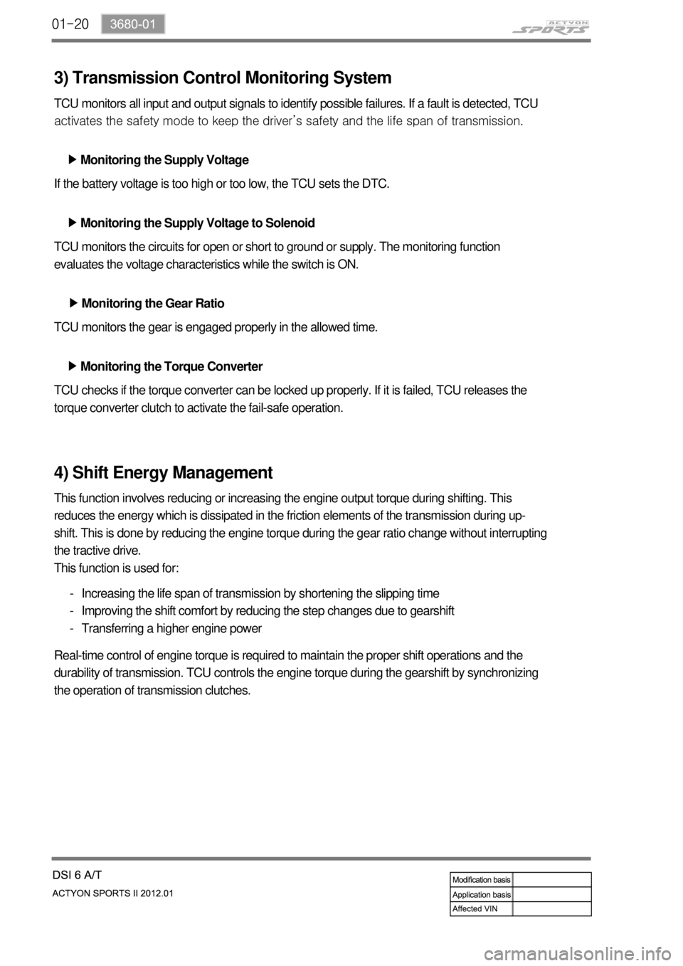
3) Transmission Control Monitoring System
TCU monitors all input and output signals to identify possible failures. If a fault is detected, TCU
<0088008a009b0090009d0088009b008c009a0047009b008f008c0047009a0088008d008c009b00a0004700940096008b008c0047009b009600470092008c008c00970047009b008f008c0047008b00990090009d008c009902c5009a0047009a0088008d00
8c009b00a0004700880095008b0047009b008f008c00470093>ife span of transmission.
Monitoring the Supply Voltage ▶
Monitoring the Supply Voltage to Solenoid ▶
Monitoring the Gear Ratio ▶
Monitoring the Torque Converter ▶ If the battery voltage is too high or too low, the TCU sets the DTC.
TCU monitors the circuits for open or short to ground or supply. The monitoring function
evaluates the voltage characteristics while the switch is ON.
TCU monitors the gear is engaged properly in the allowed time.
TCU checks if the torque converter can be locked up properly. If it is failed, TCU releases the
torque converter clutch to activate the fail-safe operation.
4) Shift Energy Management
This function involves reducing or increasing the engine output torque during shifting. This
reduces the energy which is dissipated in the friction elements of the transmission during up-
shift. This is done by reducing the engine torque during the gear ratio change without interrupting
the tractive drive.
This function is used for:
Increasing the life span of transmission by shortening the slipping time
Improving the shift comfort by reducing the step changes due to gearshift
Transferring a higher engine power -
-
-
Real-time control of engine torque is required to maintain the proper shift operations and the
durability of transmission. TCU controls the engine torque during the gearshift by synchronizing
the operation of transmission clutches.
Page 705 of 828

11-4
2) Specification of Steering Wheel Angle Sensor
3) Specification of Sensor Cluster
Description Specification
Operating voltage 9 to 16 V
Maximum output current 10 mA
Maximum detection angle speed±100°/Sec
Operating temperature-30 to 75 ℃
Supplying voltage 9 to 16 V (battery voltage)
Output voltage (HI) approx. 3.50 V (3.0 to 4.1 V)
Output voltage (LO) approx. 1.50 V (1.3 to 2.0 V)
Pulses/rev 45 pulses/rev
Description Specification
Supplying voltage approx. 12 V (8 to 16 V)
Current consumption below 250 mA -
Operating range Yaw rate sensor± 75 °/Sec
Lateral/longitudinal sensor± 14.7m/Sec²
Page 785 of 828

02-38810-01
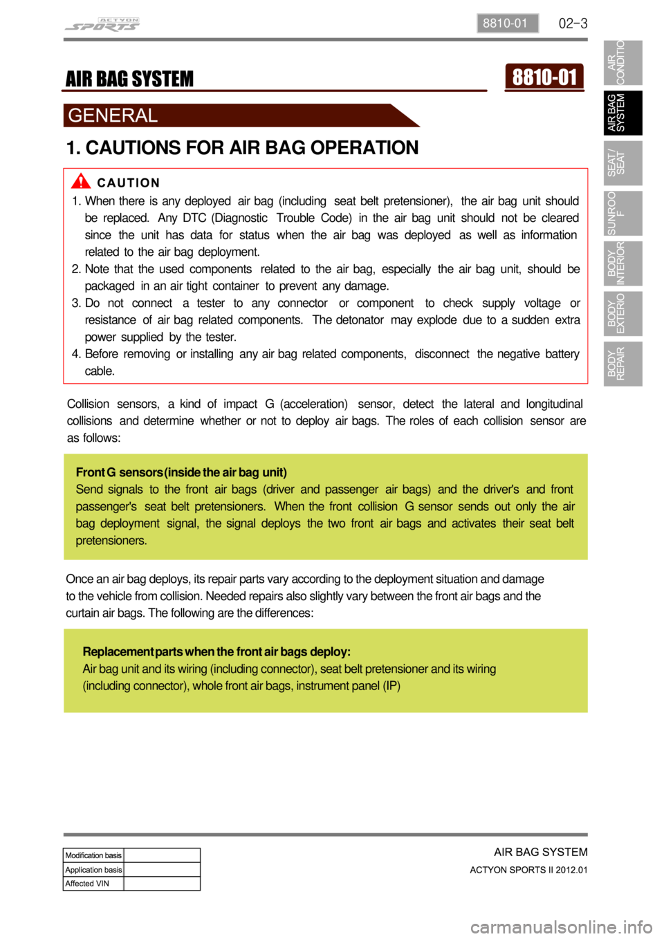
1. CAUTIONS FOR AIR BAG OPERATION
When there is any deployed air bag (including seat belt pretensioner), the air bag unit should
be replaced. Any DTC (Diagnostic Trouble Code) in the air bag unit should not be cleared
since the unit has data for status when the air bag was deployed as well as information
related to the air bag deployment.
Note that the used components related to the air bag, especially the air bag unit, should be
packaged in an air tight container to prevent any damage.
Do not connect a tester to any connector or component to check supply voltage or
resistance of air bag related components. The detonator may explode due to a sudden extra
power supplied by the tester.
Before removing or installing any air bag related components, disconnect the negative battery
cable. 1.
2.
3.
4.
Collision sensors, a kind of impact G (acceleration) sensor, detect the lateral and longitudinal
collisions and determine whether or not to deploy air bags. The roles of each collision sensor are
as follows:
Front G sensors (inside the air bag unit)
Send signals to the front air bags (driver and passenger air bags) and the driver's and front
passenger's seat belt pretensioners. When the front collision G sensor sends out only the air
bag deployment signal, the signal deploys the two front air bags and activates their seat belt
pretensioners.
Once an air bag deploys, its repair parts vary according to the deployment situation and damage
to the vehicle from collision. Needed repairs also slightly vary between the front air bags and the
curtain air bags. The following are the differences:
Replacement parts when the front air bags deploy:
Air bag unit and its wiring (including connector), seat belt pretensioner and its wiring
(including connector), whole front air bags, instrument panel (IP)
Page 794 of 828

02-12
4. DEPLOYMENT
According to the collision deceleration rate that each collision G sensor reads, the air bag unit
sends out about 2~4 or higher Amp current. This current generates some heat, which fires the
detonator in the inflator.
The table shows the basic inner resistance of the air bag related module and the basic instant
current necessary for firing.
1) Air Bag System Deployment (Firing Loop)
2) Air Bag Deployment Signal Output (Crash Out)
When the air bag deploys, the signal is sent to STICS to perform the basic security operation
which is the automatic door unlock function that release the automatic door lock mode.
Deployment signal
output (crash out)200ms
Automatic Door Unlock (Crash unlock: unlock when colliding) ▶
The air bag collision signal input cannot be accepted within 7 seconds after turning the ignition
key to "ON" position.
After this period, the door lock system outputs "UNLOCK" for all doors for 5 seconds from 40
ms after receiving the air bag collision signal.
Even though the key is turned to "OFF" position during the output of "UNLOCK", the output
continues on for remaining period.
The function is erased when turning "OFF" the ignition switch. 1.
2.
3.
4.
Air bag module
DAB /PABSeat belt pretensioner(BPA)
Resistance (at -30 ~ 85˚C) 2 ±0.3 Ω 2.15 ±0.35 Ω
Firing current 1.2 Amps 0.8 Amps
Please do not connect a tester to any air bag connector or single item to measure the
supplied power or resistance. The detonator may explode due to a sudden extra power
supplied by the tester.
Before removing or installing any air bag related components, disconnect the negative
battery cable. -
-
Page 816 of 828

04-37340-00
1. SPECIFICATIONS
2. CAUTIONS WHEN WORKING
Wear clean work clothes and gloves.
Replace and wash the gloves frequently.
Any unauthorized modification or operational test is not allowed since the sunroof motor and
control unit are preset at the factory.
Take care not to drop the sunroof assembly when removing it and do not keep it right up. 1.
2.
3.
4.
Operating voltage 9 ~ 16 V
Operating current (open & close) Max. 6 A
At no load Max. 2 A
Leakage current Max. 1 mA or less
Roof motor operating speed (at opening and closing)1.2 ± 0.5 sec./100 mm
Motor overload stop conditionsCurrent for up to 26 A and torque
(load) for up to 8.3 Nm
Opening amount230 ± 3
Vertical/horizontal tolerance for sunroof glass panel± 2 mm/± 2.5 mm
3. CAUTIONS FOR OPERATION
Even though the sunroof can be operated when the engine is not running, operating the
sunroof repeatedly with the engine turned off will run down the battery. Operate the sunroof
while the engine is running.
When the sunroof operation is completed, release the switch. Keeping pressing the switch can
result in malfunction.
Especially in winter, never operate the sunroof if operation areas are iced. Wait until melted.
Make sure that the sunroof is completely closed when leaving the vehicle. Leaving the vehicle
with the sunroof open result in a theft. In addition, rain or snow can get into the vehicle through
the open sunroof.
When the sunroof is fully open, wind buffeting symptom can be worse. In this case, try to
adjust the sunroof position manually or open the sunroof until the wind buffeting is disappeared
Parts of the body can be trapped in the sunroof and can be struck by passing objects. Do not
stick hands, head or anything else out of the openings.
Remove any dirt and foreign material stuck on the edge of the sunroof glass periodically.
Noise can occur due to friction when operating the sunroof. -
-
-
-
-
-