2012 SSANGYONG NEW ACTYON SPORTS sensor
[x] Cancel search: sensorPage 549 of 828

01-53680-01
2. FEATURES AND SPECIFICATIONS
1) Specifications
Description DSI M78 (6-speed) Remarks
Gear ratio1st 3.53:1
2nd 2.14:1
3rd 1.48:1
4th 1.16:1
5th 0.87:1
6th 0.68:1
Reverse 3.09:1
Transmission flui
dFluid Fuchs FES 209-3292 ATF
Capacity Approx. 9.5 L
Change interval Check the fluid at every
30,000 km or 1 year, and
change it if necessary.Under the severe driving
conditions, change the fluid
at every 60,000 km.
Resistance of oil
temperature
sensor-20 430.7 ~ 533.9 kΩ
0 146.8 ~ 175.7 kΩ
20 56.74 ~ 65.86 kΩ
100 3.201 ~ 3.399 kΩ
Gear position
sensor1 -
2 -
3 -
D 2.686 kΩ ± 8%
N 5.036 kΩ ± 8%
R 8.953 kΩ ± 8%
P 16.786 kΩ ± 8%
Severe driving conditions? *
Towing a trailer or off-road driving (Inspect the
leak of fl uid at any time, occasionlly)
Taxi, patrol service or delivery service
(extended idling and excessive driving with low
speed)
Frequent stop-and-go traffi c, extended idling,
short driving distance -
-
-Driving in a hilly or mountainous terrain,
sandy, or dusty area
Driving frequently at high speed over 170
km/hour
Driving frequently in area where heavy
traffi c under the ambient temperature
above 32°C -
-
-
Page 553 of 828

01-93680-01
3. TIGHTENING TORQUE
Description Size x Numbers Tightening torque
Transfer case housing M12 x 32 54 ~ 68
Etension housing M12 x 32 54 ~ 68
Oil pan M6 x 16 4 ~ 6
Valve body to transmission housing M6 x 26 8 ~ 13
Valve body to transmission housing M6 x 45 8 ~ 13
Center support to transmission housing M10 x 34 20 ~ 27
Output shaft locking nut M24 x 15 100 ~ 110
Pump cover to oil pump M8 x 55 24 ~ 27
Pump cover to transmission housing M8 x 40 24 ~ 34
Pump cover to transmission housing M8 x 58 24 ~ 34
Upper valve body to lower valve body M6 x 30 15 ~ 17
Detent spring M8 x 16 20 ~ 25
Variable bleed solenoid and speed sensor
M4 x 12 2.8 ~ 3.2
Transmission oil level plug 30 ~ 35
Front cooling lines to transmission cooler
25 ~ 35
Rear cooling lines to transmission cooler
25 ~ 35
Drive plate to torque converter
40 ~ 42
Gear select lever to shaft rod
14 ~ 20
Page 555 of 828

01-113680-01
1. OVERVIEW
The six speed automatic (M78) transmission
is available in two variants: four wheel drive
and two wheel drive.
The transmission has the following features:
Six Forward Speeds
One reverse gear
A torque converter with an integral converter lock-up clutch
Electronic shift and pressure controls
A single planetary gear-set
A double planetary gear-set
Two hydraulically controlled brake bands
Three multi-plate clutches
All hydraulic functions are directed by electronic solenoids to control: -
-
-
-
-
-
-
-
-
Engagement feel
Shift feel
Shift scheduling
Modulated torque converter clutch applications ·
·
·
·
The transmission contains fully synthetic automatic transmission fluid (ATF) and is filled for life;
therefore it does not require periodic servicing.
Engine power reaches the transmission via a torque converter with integral converter lock-up
clutch.
The six forward gears and one reverse gear are obtained from a single planetary set, followed by
a double planetary set. This type of gear-set arrangement is commonly known as Lepelletier type
gear-set.
The automatic transmission is electronically controlled. The control system is comprised of the
following elements:
External transmission control unit (TCU)
Internal embedded memory module (EMM)
Input and output speed sensors
Valve body unit comprised of four on/off solenoid valves and six variable bleed solenoids
Torque converter -
-
-
-
-
Page 556 of 828

01-12
2. FEATURES
Early Downshifts with Hard Braking and Skip Shifts ▶
When heavy braking is detected, the transmission downshifts early and skips gears to provide
increased engine braking to provide gear selection for tip-in.
Gear Hold on Uphill/Downhill ▶
If the accelerator pedal is released when travelling uphill, upshifts are prevented to reduce
busyness on grades. If the accelerator pedal is released when travelling downhill, upshifts are
prevented to enhance engine braking.
Soft Engagement when Shifting to “D” and “R” Position ▶
A soft engagement feature avoids harsh take up of drive when selecting Drive or Reverse. This is
achieved by limiting engine speed and engine torque which results in a rapid, but progressive
engagement of either Drive or Reverse when moving from the Park or Neutral positions. There is
no drive engagement prevention strategy implemented on the transmission system as there is
sufficient engine strategy to protect the system. However, reverse gear engagement is prevented
until engine speed is less than 1400 rpm and the accelerator pedal position is less than 12% and
vehicle speed is less than 10 km/h.
Converter Clutch Lock-Up In All Gears ▶
The transmission features converter clutch lock-up in all gears. This feature provides improved
fuel economy and vehicle performance. It also improves transmission cooling efficiency when
towing heavy loads at low speeds, e.g. in city driving or hill terrain.
Embeded Memory Module (EMM) ▶
The embedded memory module (EMM) is
matched to the transmission's valve bodies
during transmission assembly to ensure
refined shift quality. The EMM is integrated
into the input speed sensor which is mounted
on the valve body in the transmission. The
EMM is used to store data such as valve body
calibration data and valve body serial number.
Upon installation, the TCU will download the
data from the EMM and utilise this data in the
operation of the transmission.
1) Features
Page 557 of 828

01-133680-01
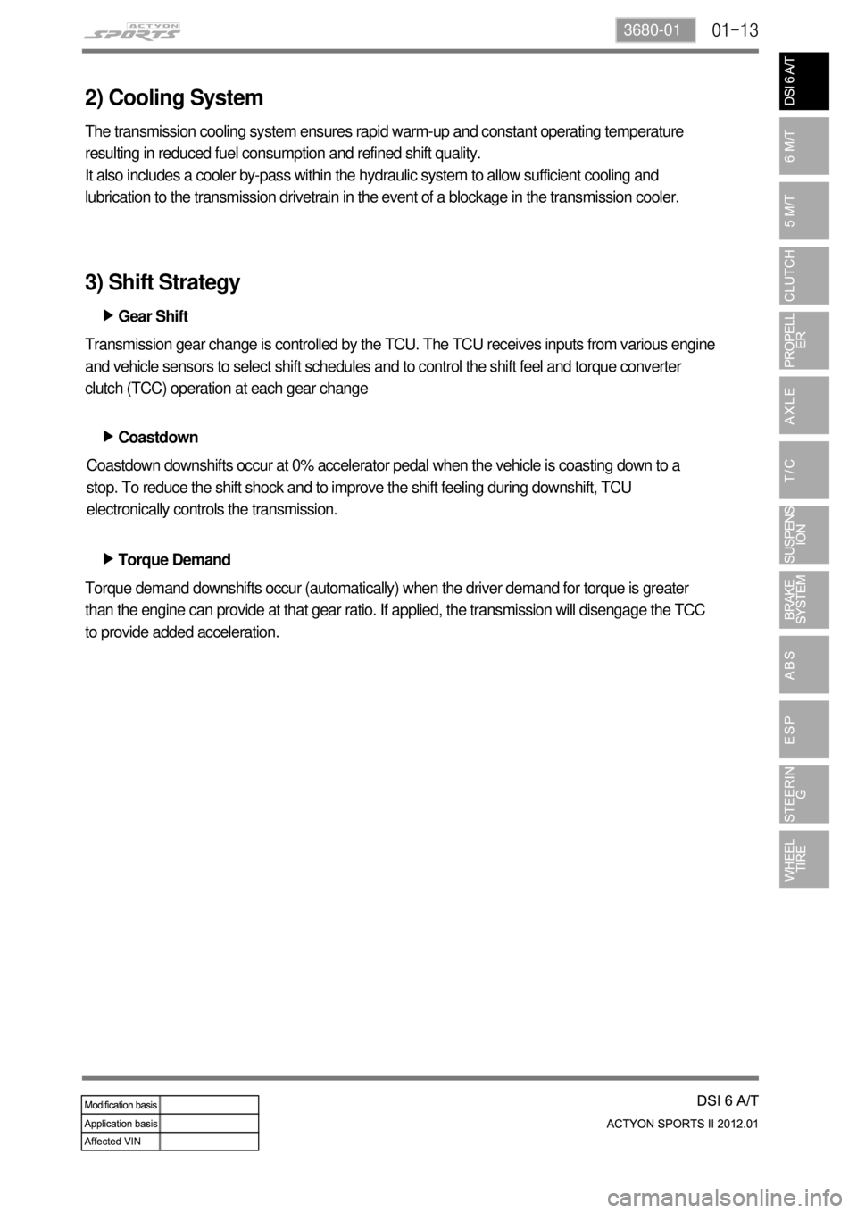
2) Cooling System
The transmission cooling system ensures rapid warm-up and constant operating temperature
resulting in reduced fuel consumption and refined shift quality.
It also includes a cooler by-pass within the hydraulic system to allow sufficient cooling and
lubrication to the transmission drivetrain in the event of a blockage in the transmission cooler.
Gear Shift ▶
Coastdown ▶
Torque Demand ▶ Transmission gear change is controlled by the TCU. The TCU receives inputs from various engine
and vehicle sensors to select shift schedules and to control the shift feel and torque converter
clutch (TCC) operation at each gear change
Coastdown downshifts occur at 0% accelerator pedal when the vehicle is coasting down to a
stop. To reduce the shift shock and to improve the shift feeling during downshift, TCU
electronically controls the transmission.
Torque demand downshifts occur (automatically) when the driver demand for torque is greater
than the engine can provide at that gear ratio. If applied, the transmission will disengage the TCC
to provide added acceleration.
3) Shift Strategy
Page 561 of 828

01-173680-01
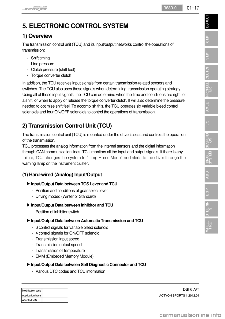
5. ELECTRONIC CONTROL SYSTEM
1) Overview
The transmission control unit (TCU) and its input/output networks control the operations of
transmission:
Shift timing
Line pressure
Clutch pressure (shift feel)
Torque converter clutch -
-
-
-
In addition, the TCU receives input signals from certain transmission-related sensors and
switches. The TCU also uses these signals when determining transmission operating strategy.
Using all of these input signals, the TCU can determine when the time and conditions are right for
a shift, or when to apply or release the torque converter clutch. It will also determine the pressure
needed to optimise shift feel. To accomplish this, the TCU operates six variable bleed control
solenoids and four ON/OFF solenoids to control the operations of transmission.
2) Transmission Control Unit (TCU)
The transmission control unit (TCU) is mounted under the driver's seat and controls the operation
of the transmission.
TCU processes the analog information from the internal sensors and the digital information
through CAN communication lines. TCU monitors all the input and output signals. If there is any
<008d008800900093009c0099008c00530047007b006a007c0047008a008f00880095008e008c009a0047009b008f008c0047009a00a0009a009b008c00940047009b0096004702c800730090009400970047006f00960094008c004700740096008b008c02
c9004700880095008b004700880093008c0099009b009a0047>to the driver through the
warning lamp on the instrument cluster.
(1) Hard-wired (Analog) Input/Output
Input/Output Data between TGS Lever and TCU ▶
Position and conditions of gear select lever
Driving moded (Winter or Standard) -
-
Position of inhibitor switch - Input/Output Data between Inhibitor and TCU ▶
6 control signals for variable bleed solenoid
4 control signals for ON/OFF solenoid
Transmission input speed
Transmission output speed
Transmission oil temperature
EMM (Embeded Memory Module) -
-
-
-
-
- Input/Output Data between Automatic Transmission and TCU ▶
Input/Output Data between Self Diagnostic Connector and TCU ▶
Various DTC codes and TCU information -
Page 615 of 828

03-73170-01
2) Function of N Switch
(1) Aids a smooth start of the vehicle by raising the RPM during the gear
shifting when the engine is cold.
When the vehicle is trying to start from the stopped state (vehicle speed below 3 km/h), the N
switch determines the shifting timing by using the clutch switch and the N switch. It raises the
engine RPM (100 ~ 200 rpm). Operation conditions are as follows.
The vehicle speed is at the stopped state (Vehicle speed below 3km/h detection).
While depressing the clutch (Clutch switch detection).
The gear lever is at a position other than neutral (N switch detection).
Start the vehicle while depressing the clutch pedal (Clutch switch detection).
The RPM increases in accordance with the temperature of the engine coolant
(Engine coolant temperature sensor detection). -
-
-
-
-
appx. 100 rpm increase
appx. 100 ~ 170 rpm increase
<008800970097009f00550047005f005700b6006a0047004f0095009600990094008800930047009b008c00940097008c00990088009b009c0099008c00470096008d0047009b008f008c0047008c0095008e00900095008c0047008a009600960093008800
95009b005000610047008800990096009c0095008b00470059>00 rpm ·
·
·
When the gear has been smoothly shifted and the vehicle speed exceeds 3km/h, it returns to
the previous operation interval of the engine RPM. -
In case of Actyon, the N switch signal is transmitted to the instrument panel, and then the
instrument panel transmits it to the engine ECU through the CAN communication.
Vehicle Made After 04.09.15 Actyon
Page 651 of 828

09-34850-01
1. SPECIFICATION
Unit Description Specification
Front brake Type Ventilated disc
Outer diameter of discØ294 mm
Inner diameter of caliper cylinderØ43.0 x 2 mm
Thickness of disc 28 mm (wear limit: 25.4 mm)
Area of brake pad Above 60 cm2
Pad wear indicator Mechanical type
Rear brake Type Solid disc
Outer diameter of discØ299 m
Thickness of disc 10.4 mm (wear limit: 8.5 mm)
Area of brake pad Above 28.8 cm2
Pad wear indicator Mechanical type
Brake booster Type Vacuum assist type
Size8” + 9” (Tandem)
Master cylinder Type Tandem type(integrated level sensor)
Inner diameter of cylinderØ26.99 mm
Brake pedal Maximum operating stroke 150 mm
Pedal ratio 4 : 1
Free play 3 to 10 mm
Parking brake Type Mechanically expanded rear lining
Operating type Hand operated type
Inner diameter of drumØ190 mm
Brake oil Specification DOT 4
Capacity 0.7 to 0.8 liters
Service Interval: Change the brake oil at every 2 years
DOT?
It is the quality grade of brake fluid established by US Department of Transportation.