Page 100 of 1082
01-4
2. MAJOR COMPONENTS
Front View ▶
Vacuum pump
Oil filter assembly
Camshaft position sensor
Power steering pump pulley
Water pump pulley
Alternator pulley
Idler pulley No. 1
A/C compressor pulley
Auto tensioner
Idler pulley No. 2
Isolation damper
Rear View ▶
E-EGR valve
Fuel temperature sensor
Fuel HP pump assemblyE-VGT actuator
Coolant temperature sensor
IMV valve
Magnetic triggering
Crankshaft position sensor
Page 113 of 1082
02-6
품명 규격 볼트
수량규정토오크(Nm) 비고
(총 토오크)
Oil gauge tubeM6×16110 ± 1Nm-
Oil filter cap 125 ± 2.5Nm-
Fuel railM8×35225 ± 2.5Nm-
Injector clamp boltM6×6029 ± 1.0Nm
130˚ + 10˚-
High pressure pipe
(between HP pump and
fuel rail)M17 130 ± 3Nm
-
High pressure pipe
(between fuel rail and
injector)M17 430 ± 3Nm
-
Crank position sensor
M5×1418 ± 0.4Nm
-
Main wiringM6×16510 ± 1Nm-
Intake duct M8x25 325 ± 2.5Nm-
Power steering pumpM8×100325 ± 2.5Nm-
Mass balance shaft
(MBU)M8×45630 ± 3Nm-
Cylinder head front cove
rM6×10510 ± 1Nm-
품명 규격볼트
수량규정토오크(Nm)비고
(총 토오크)
Timing gear case coverM6×40710 ± 1Nm-
M6×45110 ± 1Nm-
M6×50310 ± 1Nm-
Cylinder head coverM6×352110 ± 1Nm-
Component Size
QuantityTightening torque
(Nm)Remark
(Total torque)
Idle pulley/Tensioner
pulley145 ± 4.5Nm
-
Glow plug M5 420 ± 2Nm-
Vacuum pumpM8×25310 ± 1Nm-
Page 138 of 1082
03-30000-00
1. SPECIFICATION
Description Specification
Fuel Diesel
Fuel filterTypeFuel heater + priming pump + water separator
integrated type
Filter type Changeable filter element type
every 40,000 km
every 45,000 km
Water accumulating capacity 200 cc
Heater capacity 250W 13.5V
Injector System pressure 1800 bar
High pressure fuel
pumpType Eccentric cam/Plunger type
Operating type Gear driven type
Normal operating temperature-40 ~ 125℃
Operating pressure 1800 bar
Operating temperature-30℃ ~ 120℃
Low pressure fuel
pumpType Vane type
Gear ratio (pump/engine) 0.5 : 1
Pressure 6 bar
Fuel tankCapacity 60 L
Material Plastic
Fuel sender Dual sender type
Change intervalEU
GEN
Page 140 of 1082

03-50000-00
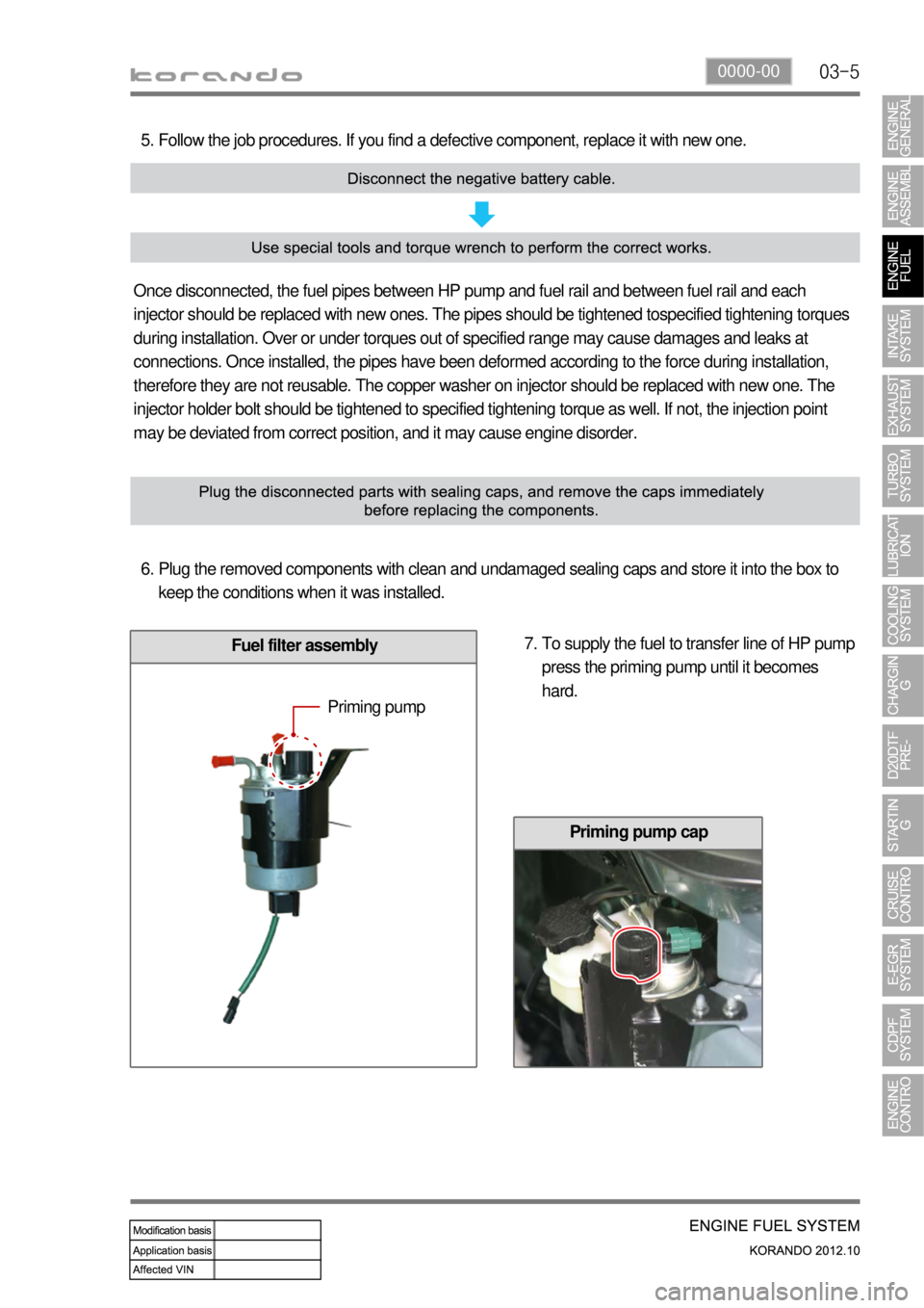
Fuel filter assembly
Follow the job procedures. If you find a defective component, replace it with new one. 5.
Once disconnected, the fuel pipes between HP pump and fuel rail and between fuel rail and each
injector should be replaced with new ones. The pipes should be tightened tospecified tightening torques
during installation. Over or under torques out of specified range may cause damages and leaks at
connections. Once installed, the pipes have been deformed according to the force during installation,
therefore they are not reusable. The copper washer on injector should be replaced with new one. The
injector holder bolt should be tightened to specified tightening torque as well. If not, the injection point
may be deviated from correct position, and it may cause engine disorder.
Plug the removed components with clean and undamaged sealing caps and store it into the box to
keep the conditions when it was installed. 6.
To supply the fuel to transfer line of HP pump
press the priming pump until it becomes
hard. 7.
Priming pump
Priming pump cap
Page 145 of 1082
03-10
3) Pressure Test for Fuel System in DI Engine
(1) Test device (Tool kit)
Tool kit for high pressure line
Tool kit for low pressure line
(2) Pre-inspection
Connections in fuel supply line
Fuel level in fuel tank
Air in fuel supply line (air bubbles in fuel supply line or fuel)
Fuel leaks from fuel supply line (low/high pressure line)
Used the specified
Fuel filter contamination -
-
-
-
-
-
Page 146 of 1082
03-110000-00
(3) DTC Check
If several DTCs are output simultaneously, check the electric wiring for open or short circuit.
Check the low pressure fuel system and fuel filter and confirm that there are no abnormalities. Carry
out the high pressure fuel system check.
Page 150 of 1082
03-150000-00
(6) Low Pressure System Pressure Test
Inspection procedure ▶
All wirings/connectors and fuel lines should be
connected and the engine should work
properly.
Prepare a special tool for low pressure test
and clean it thoroughly to prevent foreign
materials from entering. 1.
2.
Disconnect the key connector for fuel filter connection, and connect both connectors to the fuel filter
and hose. 3.
Start the engine and check visually for clogged low pressure fuel system, excessive air or air entry.
If the fuel flow is not sufficient or air is in the fuel, repair the leak area. 4.
5.
Page 155 of 1082

03-20
3. CAUTIONS FOR DI ENGINE
1) Cautions for DI Engine
This chapter describes the cautions for DI engine equipped vehicle. This includes the water separation
from engine, warning lights, symptoms when engine malfunctioning, causes and actions.
DI Engine 1.
Comparatively conventional diesel engines, DI engine controls the fuel injection and timing electrically,
delivers high power and reduces less emission.
System Safety Mode 2.
When a severe failure has been occurred in a vehicle, the system safety mode is activated to protect the
system. It reduces the driving force, restricts the engine speed (rpm) and stops engine operation. Refer
to "Diagnosis" section in this manual.
Engine CHECK Warning Lamp 3.
The Engine CHECK warning lamp on the instrument cluster comes on when the fuel or
major electronic systems of the engine are not working properly. As a result, the
<008c0095008e00900095008c02c5009a004700970096009e008c009900470096009c009b0097009c009b00470094008800a00047008b008c008a0099008c0088009a008c0047009600990047009b008f008c0047008c0095008e00900095008c0047009400
8800a00047009a009b0088009300930055>
Water Separator Warning Lamp 4.
When the water level inside water separator in fuel filter exceeds a certain level (approx.
45 cc), this warning light comes on and buzzer sounds.
Also, the driving force of the vehicle decreases (torque reduction). If these conditions
occur, immediately drain the water from fuel filter.