2012 SSANGYONG KORANDO air conditioning
[x] Cancel search: air conditioningPage 290 of 1082

15-14
3. Idle Speed Controller
The idle speed controller consists of 2 principal modules:
The first module determines the required idle speed according to:
* The operating conditions of the engine (coolant temperature, gear engaged)
* Any activation of the electrical consumers (power steering, air conditioning, others)
* The battery voltage
* The presence of any faults liable to interface with the rail pressure control or the injection control. In
this case, increase the idle speed to prevent the engine from stalling.
The second module is responsible for providing closed loop control of the engine's idle speed by
adapting the minimum fuel according to the difference between the required idle speed and the
engine speed. -
-
4. Flow Limitation
The flow limitation strategy is based on the following strategies:
The flow limitation depending on the filling of the engine with air is determined according to the
engine speed and the air flow. This limitation allows smoke emissions to be reduced during
stabilized running.
The flow limitation depending on the atmospheric pressure is determined according to the engine
speed and the atmospheric pressure. It allows smoke emissions to be reduced when driving at
altitude.
The full load flow curve is determined according to the gear engaged and the engine speed. It
allows the maximum torque delivered by the engine to be limited.
A performance limitation is introduced if faults liable to upset the rail pressure control or the
injection control are detected by the system. In this case, and depending on the gravity of the fault,
the system activates: -
-
-
-
Reduced fuel logic 1: Guarantees 75 % of the performance without limiting the engine speed.
Reduced fuel logic 2: Guarantees 50 % of the performance with the engine speed limited to 3,000 rpm.
Reduce fuel logic 3: Limits the engine speed to 2,000 rpm.
The system chooses the lowest of all values.
A correction depending on the coolant temperature is added to the flow limitation. This correction makes
it possible to reduce the mechanical stresses while the engine is warming up. The correction is
determined according to the coolant temperature, the engine speed and the time which has passed
since starting.
Superchager Flow Demand
The supercharge flow is calculated according to the engine speed and the coolant temperature. A
correction depending on the air temperature and the atmospheric pressure is made in order to increase
the supercharge flow during cold starts. It is possible to alter the supercharge flow value by adding a flow
offset with the aid of the diagnostic tool.
Page 310 of 1082

15-34
Coolant temp.
sensor
(8) Cooling fan control
a. Overview of cooling fan and A/C compressor
The cooling system maintains the engine temperature at an efficient level during all engine operating
conditions. The water pump draws the coolant from the radiator. The coolant then circulates through
water jackets in the engine block, the intake manifold, and the cylinder head. When the coolant reaches
the operating temperature of the thermostat, the thermostat opens. The coolant then goes back to the
radiator where it cools. The heat from automatic transaxle is also cooled down through the radiator by
circulating the oil through the oil pump.
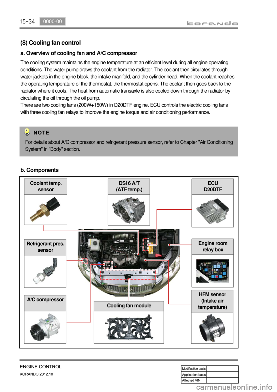
There are two cooling fans (200W+150W) in D20DTF engine. ECU controls the electric cooling fans
with three cooling fan relays to improve the engine torque and air conditioning performance.
For details about A/C compressor and refrigerant pressure sensor, refer to Chapter "Air Conditioning
System" in "Body" section.
b. Components
Refrigerant pres.
sensor
A/C compressor
ECU
D20DTF DSI 6 A/T
(ATF temp.)
Cooling fan module
HFM sensor
(Intake air
temperature)
Engine room
relay box
Page 483 of 1082

15-18
6) Cooling Fan Control
(1) Overview of Cooling Fan and A/C Compressor
The cooling system maintains the engine temperature at an efficient level during all engine operating
conditions. The water pump draws the coolant from the radiator. The coolant then circulates through
water jackets in the engine block, the intake manifold, and the cylinder head. When the coolant reaches
the operating temperature of the thermostat, the thermostat opens. The coolant then goes back to the
radiator where it cools. The heat from automatic transaxle is also cooled down through the radiator by
circulating the oil through the oil pump. There are two cooling fans (180W+120W) in G20DF engine. ECU
controls the electric cooling fans with three cooling fan relays to improve the engine torque and air
conditioning performance.
(2) Components
Refrigerant pressure
sensorCoolant temperature
sensorG20DF Engine
ECURelay box in engine
compartment
A/C compressorCooling fan moduleT-MAP sensor
Page 1014 of 1082

01-136810-00
The refrigerant is converted from liquid to gas in the evaporator.
(The refrigerant in the form of fog in the evaporator is vaporized actively)
At this time the refrigerant, in the form of liquid, absorbs the heat in the air which is need for
evaporation (latent heat) and is cooled down. Then the blower blows the cooled air inside the vehicle
to lower the temperature.
There are liquid refrigerant from the expansion valve and evaporated refrigerant in the evaporator.
The evaporation temperature can be predicted from the evaporation pressure (i.e. relationship
between saturation pressure and saturation temperature).
It is important to keep the pressure inside the evaporator low, so that the refrigerant is evaporated at
low temperature to make sure the completely evaporated refrigerant is entered into the compressor. -
-
-
-
- (4) Evaporator (3) Expansion (2) Condensation
The liquid refrigerant lowers the pressure making its evaporation easily accomplished.
This process (lowering the pressure to the level at which evaporation easily takes place before the
liquid refrigerant is sent to the evaporator) is called
"Adiabatic Expansion".
During adiabatic expansion, the expansion valve lowers the pressure of the refrigerant and
determines the correct amount of refrigerant going into the air conditioning evaporator.
That is, the amount of heat, which is needed to stop the evaporation, is determined according to the
cooling load.
The expansion valve detects this and regulates the amount of the refrigerant exactly. -
-
-
-
-The high pressure and high temperature gas (refrigerant) from the compressor is cooled down by
the fresh air entered into the condenser. Then, this gas is converted to liquid and collected in the
receiver drier.
The heat generated from the high pressure refrigerant is dissipated to the ambient air, and it is called
"heat of condensation".
The heat of condensation is the summation of the heat of vaporization (heat that the refrigerant
absorbs from the inside of the vehicle) and the calorific value converted from the amount of work
which is needed to compress. -
- 3) Description for Each Cycle
(1) Compression
The evaporated refrigerant in the evaporator enters to the compressor. And the refrigerant gas is
compressed until it can be liquefied at ambient temperature.
Thus, the low refrigerant pressure is maintained so that the liquid refrigerant can be evaporated
actively at low temperature (around 0℃). -
-