Page 830 of 1082
01-20
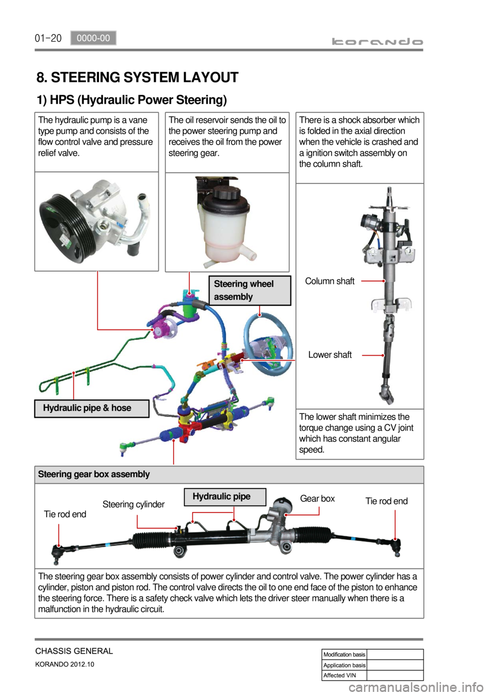
Steering gear box assembly
The steering gear box assembly consists of power cylinder and control valve. The power cylinder has a
cylinder, piston and piston rod. The control valve directs the oil to one end face of the piston to enhance
the steering force. There is a safety check valve which lets the driver steer manually when there is a
malfunction in the hydraulic circuit.
8. STEERING SYSTEM LAYOUT
1) HPS (Hydraulic Power Steering)
The hydraulic pump is a vane
type pump and consists of the
flow control valve and pressure
relief valve.The oil reservoir sends the oil to
the power steering pump and
receives the oil from the power
steering gear.There is a shock absorber which
is folded in the axial direction
when the vehicle is crashed and
a ignition switch assembly on
the column shaft.
The lower shaft minimizes the
torque change using a CV joint
which has constant angular
speed.
Tie rod endSteering cylinderGear box
Tie rod end
Hydraulic pipeColumn shaft
Lower shaft
Steering wheel
assembly
Hydraulic pipe & hose
Page 842 of 1082
02-8
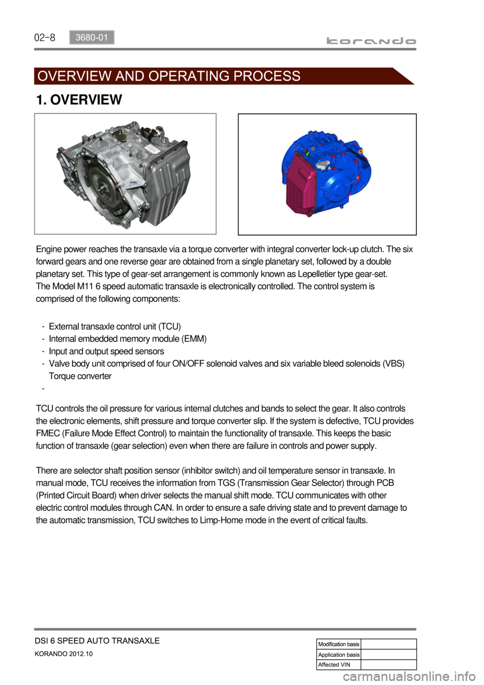
1. OVERVIEW
Engine power reaches the transaxle via a torque converter with integral converter lock-up clutch. The six
forward gears and one reverse gear are obtained from a single planetary set, followed by a double
planetary set. This type of gear-set arrangement is commonly known as Lepelletier type gear-set.
The Model M11 6 speed automatic transaxle is electronically controlled. The control system is
comprised of the following components:
External transaxle control unit (TCU)
Internal embedded memory module (EMM)
Input and output speed sensors
Valve body unit comprised of four ON/OFF solenoid valves and six variable bleed solenoids (VBS)
Torque converter -
-
-
-
-
TCU controls the oil pressure for various internal clutches and bands to select the gear. It also controls
the electronic elements, shift pressure and torque converter slip. If the system is defective, TCU provides
FMEC (Failure Mode Effect Control) to maintain the functionality of transaxle. This keeps the basic
function of transaxle (gear selection) even when there are failure in controls and power supply.
There are selector shaft position sensor (inhibitor switch) and oil temperature sensor in transaxle. In
manual mode, TCU receives the information from TGS (Transmission Gear Selector) through PCB
(Printed Circuit Board) when driver selects the manual shift mode. TCU communicates with other
electric control modules through CAN. In order to ensure a safe driving state and to prevent damage to
the automatic transmission, TCU switches to Limp-Home mode in the event of critical faults.
Page 848 of 1082
02-14
5. TRANSAXLE ELECTRONIC CONTROL SYSTEM
1) General Information
The transmission control unit (TCU) and its input/output network control the following transmission
operations:
Shift timing
Line pressure
Clutch pressure (shift feel)
Torque converter clutch -
-
-
-
also uses these signals when determining transaxle operating strategy. Using all of these input signals,
the TCU can determine when the time and conditions are right for a shift, or when to apply or release the
torque converter clutch. It will also determine the pressure needed to optimise shift feel. To accomplish
this, the TCU operates six variable bleed control solenoids and four on/off solenoids to control transaxle
operation.
2) TCU (Transmission Control Unit)
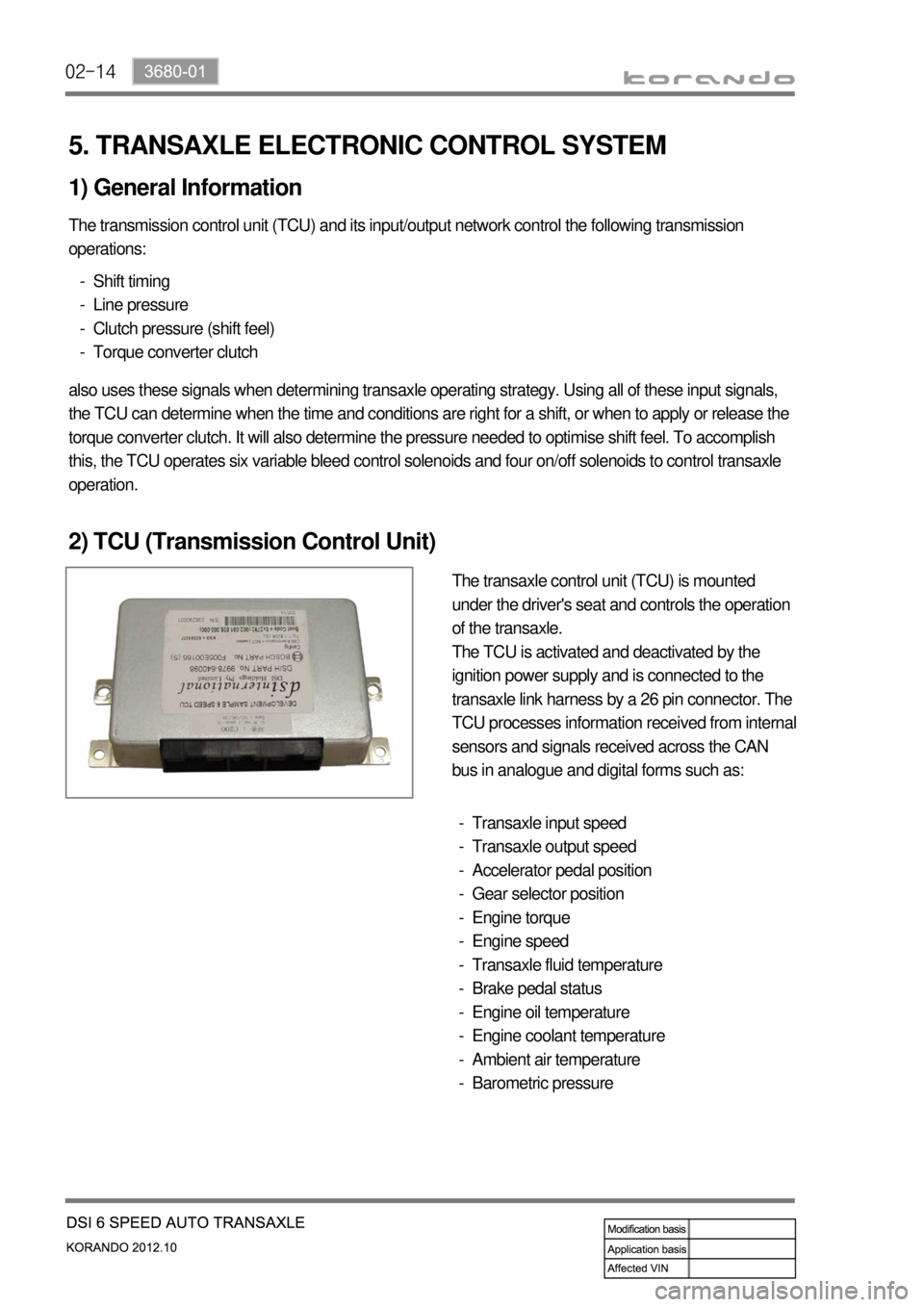
The transaxle control unit (TCU) is mounted
under the driver's seat and controls the operation
of the transaxle.
The TCU is activated and deactivated by the
ignition power supply and is connected to the
transaxle link harness by a 26 pin connector. The
TCU processes information received from internal
sensors and signals received across the CAN
bus in analogue and digital forms such as:
Transaxle input speed
Transaxle output speed
Accelerator pedal position
Gear selector position
Engine torque
Engine speed
Transaxle fluid temperature
Brake pedal status
Engine oil temperature
Engine coolant temperature
Ambient air temperature
Barometric pressure -
-
-
-
-
-
-
-
-
-
-
-
Page 871 of 1082
03-113660-01
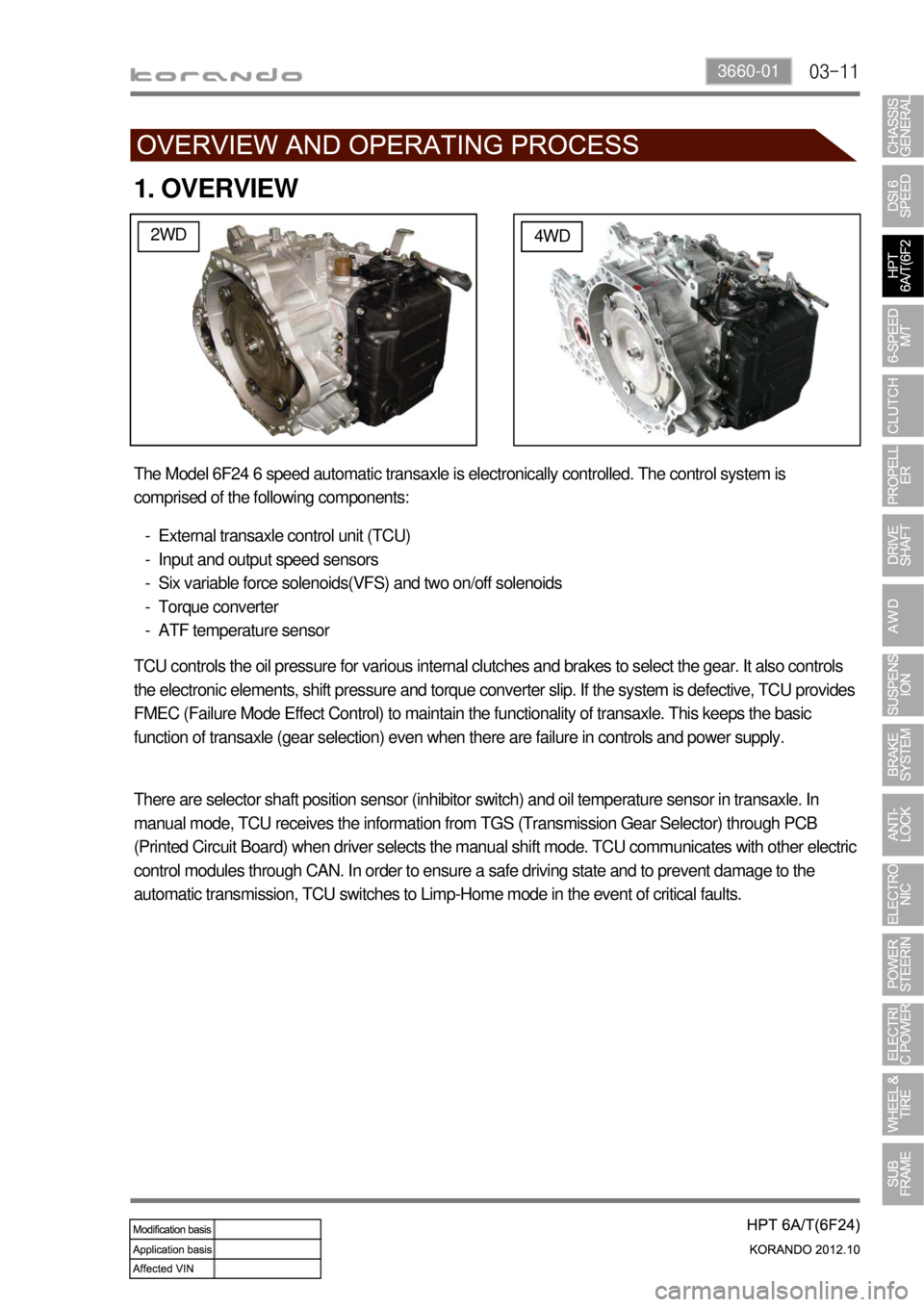
1. OVERVIEW
2WD4WD
The Model 6F24 6 speed automatic transaxle is electronically controlled. The control system is
comprised of the following components:
External transaxle control unit (TCU)
Input and output speed sensors
Six variable force solenoids(VFS) and two on/off solenoids
Torque converter
ATF temperature sensor -
-
-
-
-
TCU controls the oil pressure for various internal clutches and brakes to select the gear. It also controls
the electronic elements, shift pressure and torque converter slip. If the system is defective, TCU provides
FMEC (Failure Mode Effect Control) to maintain the functionality of transaxle. This keeps the basic
function of transaxle (gear selection) even when there are failure in controls and power supply.
There are selector shaft position sensor (inhibitor switch) and oil temperature sensor in transaxle. In
manual mode, TCU receives the information from TGS (Transmission Gear Selector) through PCB
(Printed Circuit Board) when driver selects the manual shift mode. TCU communicates with other electric
control modules through CAN. In order to ensure a safe driving state and to prevent damage to the
automatic transmission, TCU switches to Limp-Home mode in the event of critical faults.
Page 877 of 1082
03-173660-01
5. TRANSAXLE ELECTRONIC CONTROL SYSTEM
1) General Information
The transmission control unit (TCU) and its input/output network control the following transmission
operations:
Shift timing
Line pressure
Clutch pressure (shift feel)
Torque converter clutch -
-
-
-
also uses these signals when determining transaxle operating strategy. Using all of these input signals,
the TCU can determine when the time and conditions are right for a shift, or when to apply or release the
torque converter clutch. It will also determine the pressure needed to optimise shift feel.
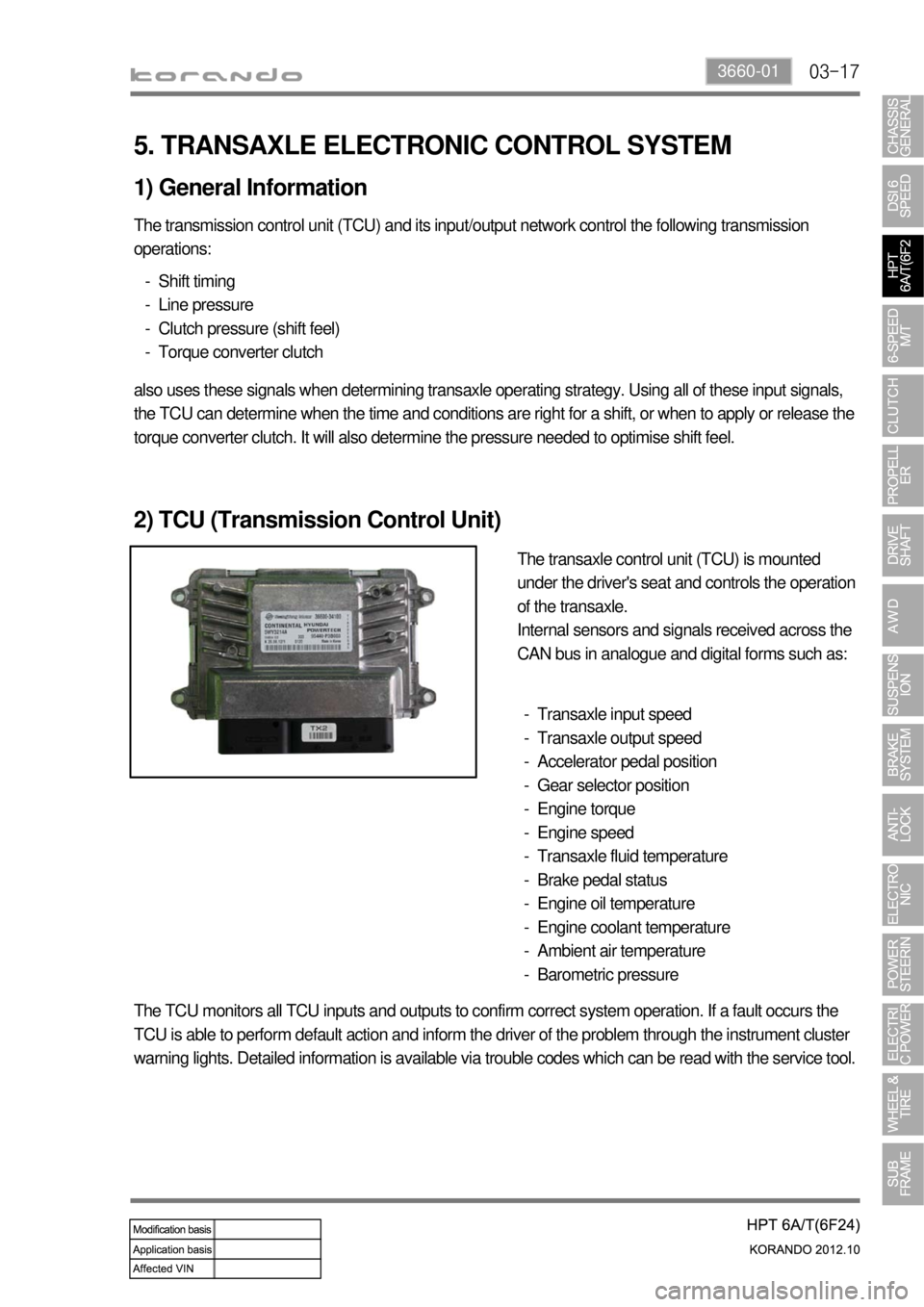
2) TCU (Transmission Control Unit)
The transaxle control unit (TCU) is mounted
under the driver's seat and controls the operation
of the transaxle.
Internal sensors and signals received across the
CAN bus in analogue and digital forms such as:
Transaxle input speed
Transaxle output speed
Accelerator pedal position
Gear selector position
Engine torque
Engine speed
Transaxle fluid temperature
Brake pedal status
Engine oil temperature
Engine coolant temperature
Ambient air temperature
Barometric pressure -
-
-
-
-
-
-
-
-
-
-
-
The TCU monitors all TCU inputs and outputs to confirm correct system operation. If a fault occurs the
TCU is able to perform default action and inform the driver of the problem through the instrument cluster
warning lights. Detailed information is available via trouble codes which can be read with the service tool.
Page 900 of 1082
04-4
2. TIGHTENING TORQUE
DescriptionTightening torque
Amount
Clutch housing boltUpper (17 mm) 85.0 to 100 Nm 2
Front (14 mm)54.0 Nm + 20°1
Rear (14 mm) 51.3 to 56.7 Nm 2
Lower (14 mm) 56.0 to 62.0 Nm 4
Pressure plate assembly bolt (Hexagon 6 mm) 21.0 to 27.0 Nm 6
Concentric slave cylinder bolt (Hexagon 5 mm) 10 to 16 Nm 3
Concentric slave cylinder oil pipe nut 24.5 to 28.4 Nm Remove the nut if it is
necessary. (Once
removed, apply the
Loctite on the thread
before installation.)
Master cylinder nut (12 mm) 7.8 to 17.6 Nm
Master cylinder oil pipe nut (10 mm) 14.7 to 17.6 Nm
Master cylinder push rod lock nut 8.8 to 13.7 Nm
Clutch oil chamber screw and bolt (10 mm) 3.9 to 7.8 Nm
Oil pipe nut (10 mm) 14.7 to 17.6 Nm
Clutch pedal mounting nut (12 mm) 7.8 to 17.6 Nm
Stopper bolt 16 to 22 Nm
Page 951 of 1082
10-20
2) DUMP (ABS is working) Mode
Even when the hydraulic pressure on each circuit is constant, the wheel can be locked as the wheel
speed decreases. This is when the ABS HECU detects the wheel speed and the vehicle speed and
gives the optimized braking without locking the wheels. In order to prevent the hydraulic pressure from
increasing, the inlet valve will be closed, the outlet valve will be opened and the oil will flow into the low
pressure chamber. In addition, the ABS HECU operates the pump to circulate the oil in the low pressure
chamber to the master cylinder. This may make the driver to feel the brake pedal vibration and some
noises.
Solenoid valve Valve Open/Close Pump motor
Inlet valve - Normal open (NO) valve Close
ON
Outlet valve - Normal close (NC) valve Open
Page 953 of 1082
10-22
4) RISE (ABS is working) Mode
As the wheel speed increases, the inlet valve opens and the wheel's pressure increases due to the
master cylinder pressure. In addition, the pump circulates the oil in the low pressure chamber to the
wheel. As the hydraulic pressure to the wheel increases, the wheel speed will reduce. This operation
continues repetitively until there are no signs that the ABS HECU tends to lock the wheels. Since the
ABS hydraulic pressure control process takes place repeatedly for a short time, there may be some
vibration and noises at the brake pedal.
Solenoid valve Valve Open/Close Pump motor
Inlet valve - Normal open (NO) valve Open
ON
Outlet valve - Normal close (NC) valve Close