Page 871 of 1082

03-113660-01
1. OVERVIEW
2WD4WD
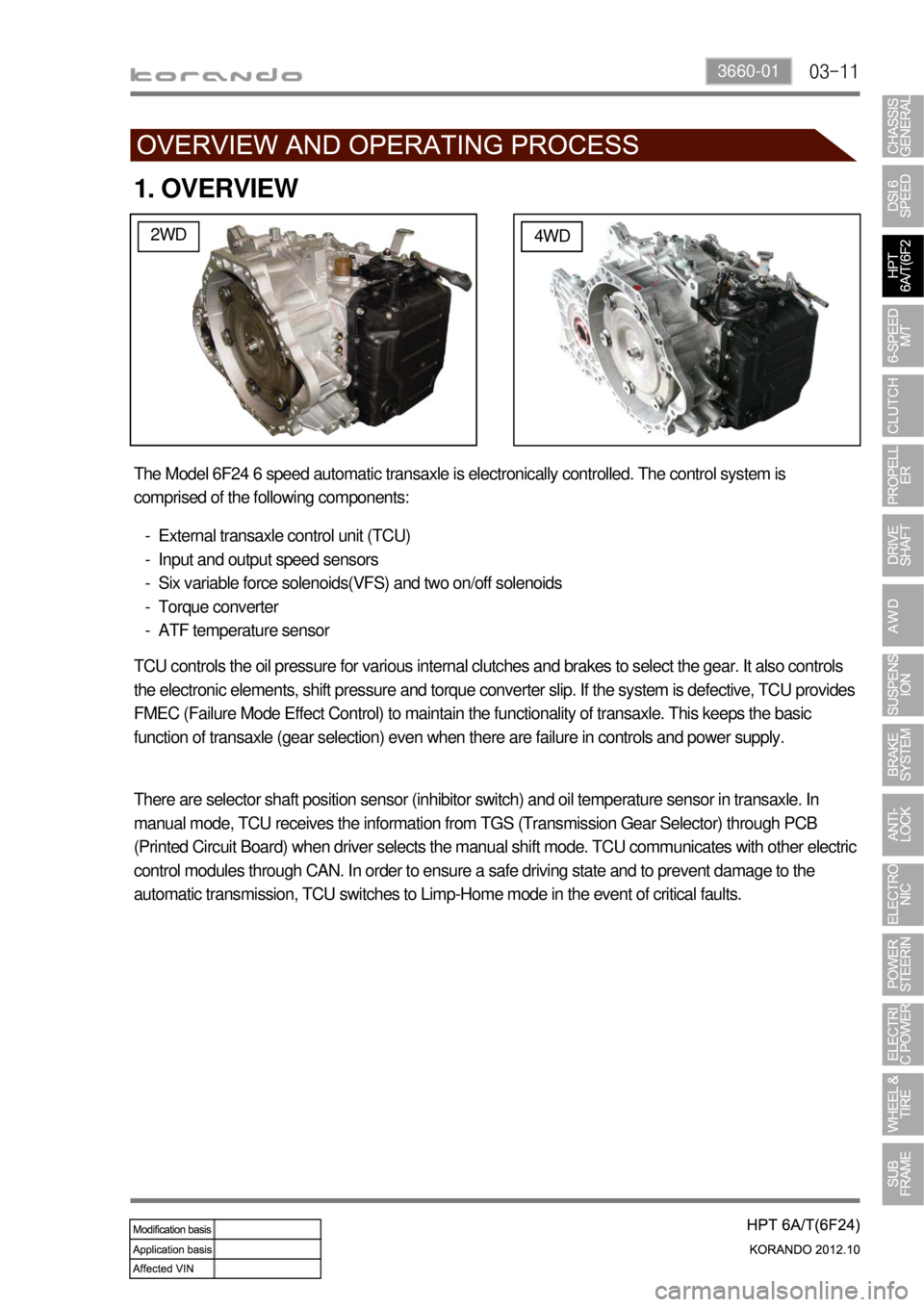
The Model 6F24 6 speed automatic transaxle is electronically controlled. The control system is
comprised of the following components:
External transaxle control unit (TCU)
Input and output speed sensors
Six variable force solenoids(VFS) and two on/off solenoids
Torque converter
ATF temperature sensor -
-
-
-
-
TCU controls the oil pressure for various internal clutches and brakes to select the gear. It also controls
the electronic elements, shift pressure and torque converter slip. If the system is defective, TCU provides
FMEC (Failure Mode Effect Control) to maintain the functionality of transaxle. This keeps the basic
function of transaxle (gear selection) even when there are failure in controls and power supply.
There are selector shaft position sensor (inhibitor switch) and oil temperature sensor in transaxle. In
manual mode, TCU receives the information from TGS (Transmission Gear Selector) through PCB
(Printed Circuit Board) when driver selects the manual shift mode. TCU communicates with other electric
control modules through CAN. In order to ensure a safe driving state and to prevent damage to the
automatic transmission, TCU switches to Limp-Home mode in the event of critical faults.
Page 877 of 1082

03-173660-01
5. TRANSAXLE ELECTRONIC CONTROL SYSTEM
1) General Information
The transmission control unit (TCU) and its input/output network control the following transmission
operations:
Shift timing
Line pressure
Clutch pressure (shift feel)
Torque converter clutch -
-
-
-
also uses these signals when determining transaxle operating strategy. Using all of these input signals,
the TCU can determine when the time and conditions are right for a shift, or when to apply or release the
torque converter clutch. It will also determine the pressure needed to optimise shift feel.
2) TCU (Transmission Control Unit)
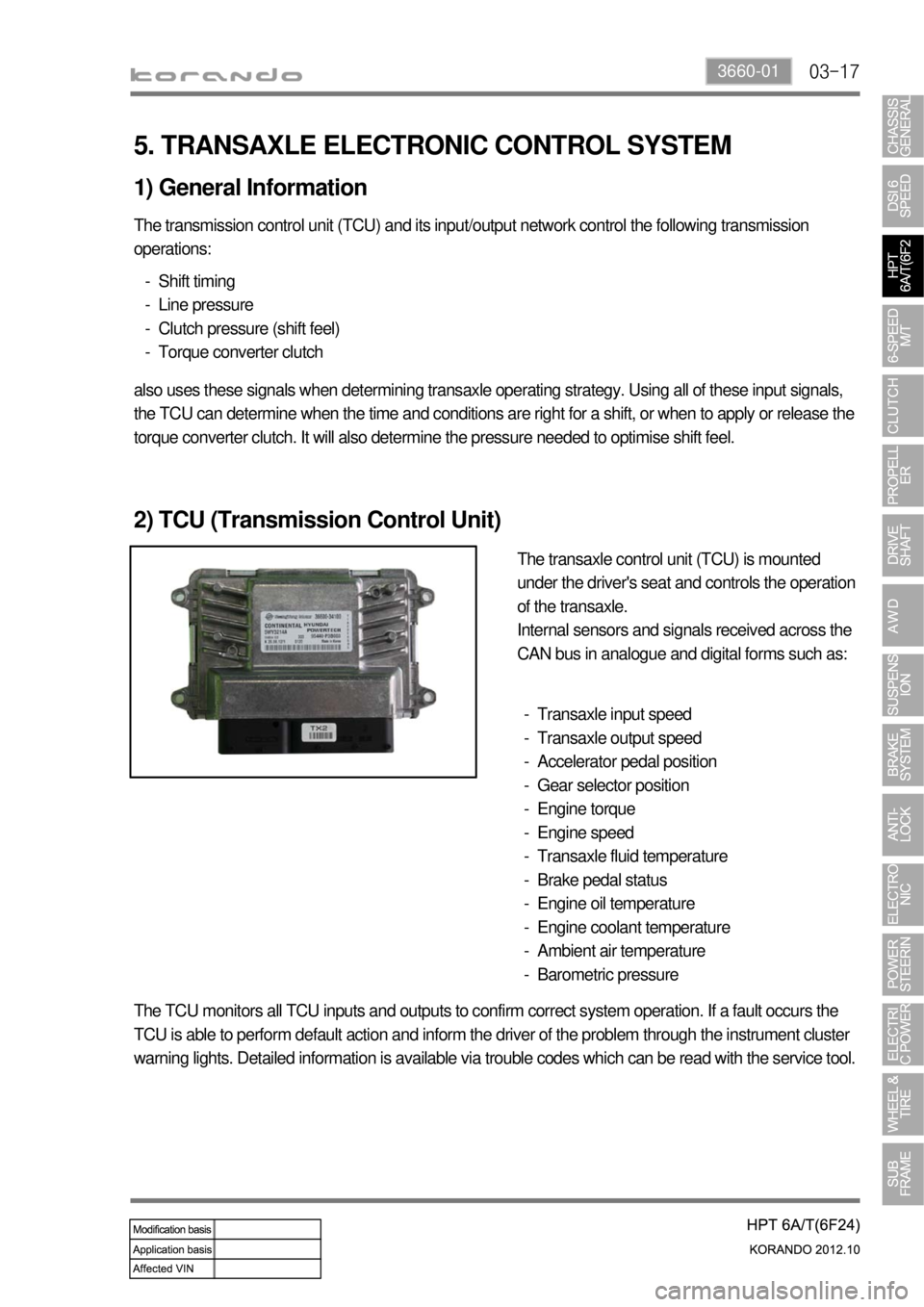
The transaxle control unit (TCU) is mounted
under the driver's seat and controls the operation
of the transaxle.
Internal sensors and signals received across the
CAN bus in analogue and digital forms such as:
Transaxle input speed
Transaxle output speed
Accelerator pedal position
Gear selector position
Engine torque
Engine speed
Transaxle fluid temperature
Brake pedal status
Engine oil temperature
Engine coolant temperature
Ambient air temperature
Barometric pressure -
-
-
-
-
-
-
-
-
-
-
-
The TCU monitors all TCU inputs and outputs to confirm correct system operation. If a fault occurs the
TCU is able to perform default action and inform the driver of the problem through the instrument cluster
warning lights. Detailed information is available via trouble codes which can be read with the service tool.
Page 888 of 1082
03-33190-01
1. SPECIFICATION
DG20DD
Model name WM6F1
Overall length 370 mm
Distance between shafts 205 mm / 70 mm
Weight (except transmission fluid) 62 kgf (2WD) / 63 kgf (4WD)
Gear ratio 1st 3.538 3.385 3.616
2nd 1.909 1.708 1.957
3rd 1.179 1.033 1.207
4th 0.814 0.786 0.905
5th 0.734 0.730 0.842
6th 0.628 0.595 0.714
Reverse 3.910 3.747 3.747
Synchronizer ring
type1st T: Triple-cone
2nd T: Triple-cone
3rd T: Triple-cone
4th D: Double-cone
5th D: Double-cone
6th S: Single-cone
Reverse T: Triple-cone
Shifting Type Remote (Cable type)
Gear selector lever
positionReversing:
Reverse ring
pull type
ItemSpecification
Remark
D20DTFD20DTF +
Low CO₂G20DF
Page 889 of 1082
03-4
Item Specification Remark
Transmission
fluidTransmission fluid SAE 75W / 85, API GL-4
Capacity 1.65 L
Replacement interval EU Inspect and replenish every 60000 km
(or 3 years)
Normal driving condition: Fill for Life
(Severe driving condition: Change every
120000 km)
GEN Inspect and replenish every 60000 km
(or 4 years)
Normal driving condition: Fill for Life
(Severe driving condition: Change every
120000 km)
Replacement
interval DSL EU
GEN
GSL Inspect and replenish every 60000 km
(or 4 years)
Normal driving condition: Fill for Life
(Severe driving condition: Change every
120000 km)
Page 890 of 1082
03-53190-01
2. TIGHTENING TORQUE
Part name Tightening torque Remark
1. Drive gear mounting bolt of differential carrier 166.6 to 176.4 Nm 10 EA
2. Reverse shaft mounting bolt 74.5 to 89.2 Nm
3. Transmission case mounting bolt 19.6 to 26.5 Nm 22 EA
4. Concentric slave cylinder mounting bolt 11.8 to 14.7 Nm 3 EA
5. Backup lamp switch 29.4 to 34.3 Nm
6. Neutral switch 29.4 to 34.3 Nm
7. Oil filler plug 58.8 to 78.4 Nm
8. Oil drain plug 58.8 to 78.4 Nm
9. Oil plug 58.8 to 78.4 Nm
10. Shift lever mounting nut 42.2 to 53.9 Nm
11. Selector lever mounting nut 42.2 to 53.9 Nm
12. Control shaft assembly mounting bolt 9.8 to 11.8 Nm 7 EA
13. Guide bolt 42.2 to 53.9 Nm
Page 892 of 1082
03-73190-01
Front view Rear view
1. OVERVIEW
This vehicle is equipped with WM6F1 M/T (Manual Transmission). This transmission is integrated with an
axle and designed to maximize the driving performance by optimizing the gear ratio according to the
engine torque.
WM6F1 M/T assembly
Page 893 of 1082
03-8
1) Characteristics of WM6F1 M/T
Both Forward and Reverse gears use the helical gear and are made of high-strength material.
Drives the clutch with a concentric slave cylinder mounting bolt.
Shifting the transmission gears is performed through the remote control cable.
A pull type clutch is used for Reverse gear shifting.
Features triple/double/single synchronization. -
-
-
-
-
Clutch housing
Transmission case
Input shaft
Concentric slave cylinder
Shift lever
Selector lever
Wiring bracket
Neutral switch
Backup lamp switch
Reverse idle shaft mounting bolt 1.
2.
3.
4.
5.
6.
7.
8.
9.
10.Control guide bolt
Oil filler plug (for servicing)
Oil drain plug
Oil filler plug (for manufacturing)
Air breather
Detent pin (for securing shift fork)
Oil seal (RH)
Oil seal (LH)
Control housing 11.
12.
13.
14.
15.
16.
17.
18.
19.
Page 903 of 1082

04-70000-00
Operating Elements ▶
The clutch "release" system consists of the clutch pedal and clutch release cylinder.
This system directly releases the clutch by using hydraulic pressure while the conventional clutch system
releases the clutch by using release lever and release fork. This system provides higher efficiency than
conventional clutch system, and its durability is superior.
Clutch master cylinder (mounted on clutch pedal)
Concentric slave cylinder pipe (mounted inside of transmission) -
-Driving elements ▶
The driving elements consist of two flat surfaces machined to a smooth finish.
One of these is the rear face of the engine flywheel and the other is the clutch pressure plate. The clutch
pressure plate is fitted into a clutch steel cover, which is bolted to the flywheel.
Driven elements ▶
The driven element is the clutch disc with a splined hub which is free to slide lengthwise along the splines
of the input shaft.
The driving and driven elements are held in contact by spring pressure. This pressure is exerted by a
diaphragm spring in the clutch cover pressure plate assembly.
2) Overview