2012 SSANGYONG KORANDO reset
[x] Cancel search: resetPage 736 of 1082

06-258510-00
SVC class instrument cluster
TRIP A TRIP B
(3) Trip switch
Whenever pressing this button, the information is displayed in the following order: Odometer, Trip A, Trip
B, Distance to empty, Average fuel consumption, Instant fuel consumption, Illumination level, Ambient air
temperature (for STD); Trip A, Trip B, Distance to empty, Average fuel consumption, Instant fuel
consumption, Illumination level, Ambient air temperature (for SVC). Press and hold (for more than 1 sec)
this button to initialize (reset) Trip A/Trip B and average fuel consumption, adjust illumination level or
change the unit of temperature.
Description ▶
The factory setting is DTE mode. ※ Display
Mode
SwitchDetecting
timeFunction
Briefly
and holdBelow 1
second
(60 to
980 ms)STD- Mode change
(Odo→Trip A→Trip B→DTE
<00470047004702e70068009d008c00990088008e008c0047008d009c008c00930047008a00960095009a009c00940097009b00900096009502e700700095009a009b00880095009b0047008d009c008c00930047008a00960095009a009c00940097009b00
9000960095>
→Illumination level→Ambient air temperature)
SVC- Mode change
(Trip A→Trip B→DTE→Average fuel consumption
→Instant fuel consumption→Illumination level
→Ambient air temperature)
Press
and holdOver 1
seconds- Reset
(Trip A, B, average fuel consumption)
- Change
<004700470047004f007000930093009c0094009000950088009b00900096009500470093008c009d008c00930047004f005d0047009b009600470058005000530047009b008c00940097008c00990088009b009c0099008c0047009c00950090009b004700
4f0b4502e90d9100500050>
Not
pressOver 3
seconds- Mode change
<004700470047004f007000930093009c0094009000950088009b00900096009500470093008c009d008c009302e70068009400890090008c0095009b00470088009000990047009b008c00940097008c00990088009b009c0099008c02e70076008b009600
50>
STD class instrument cluster
TRIP A TRIP B
Page 746 of 1082

06-358510-00
3) Cruise Control Switch
Cruise control switch
The cruise control is an automatic speed control system that maintains a desired driving speed without
using the accelerator pedal. The cruise control switch is fitted to the bottom right section of the steering
wheel. When this switch is operated, the AUTO CRUISE or ECO lamp on the instrument cluster comes
on.
The cruise control switch has a fivefold switch in it. The engine ECU can determine the current driving
condition since the resistance varies depending on the operation of the switch.
The cruise control system is operated at vehicle speed of between 38 km/h and 150 km/h. The manual
transmission is operated in the range of 3rd gear or higher.
This function can be used at the following traffic condition. (It is important to be careful for using this
function)
Cruise control (ON)
Cruise control (OFF)
Cruise control (Acceleration)Cruise control (Deceleration)
Cruise control (Reset)
Page 767 of 1082

07-14
2) Operation
(1) Front room lamp/Center room lamp
Front room lamp Center room lamp
Operating the front room lamp and center room lamp switches illuminates the driver/passenger side
lamps and center room lamp.
Room lamp control by door coupled room lamp operation ▶
If a door except the tailgate is opened after the ignition is turned off, provided that door coupled front
room lamp switch is pressed, the front room lamp and center room lamp are illuminated for 2 sec.
and then fade out for 3 sec.
If a door except the tailgate is opened and then closed while the room lamp is fading out, the room
lamp is illuminated for 2 sec. and then fades out for 3 sec. If the ignition is turned on, the room lamp
goes off immediately.
The front room lamp and center room lamp are illuminated for 30 sec. when the door is unlocked by
the REKES or passive door UNLOCK function with IGN OFF and the ignition key removed. If the
REKES or passive door UNLOCK signal is received again, the room lamps are illuminated for
another 30 sec.
The room lamp goes off immediately when the REKES or passive door LOCK signal is received or
the ignition switch is turned to ON position.
If the room lamp is turned on after the ignition key is removed (door open or room lamp switch is
pressed), it is turned off after 10 minutes by the BCM.
When the door open state is changed or the ignition is turned on after the room lamp has been turned
off automatically, the battery saver feature is reset. 1.
2.
3.
4.
5.
Page 812 of 1082
![SSANGYONG KORANDO 2012 Service Manual 10-10
If your vehicle has this feature, some audio controls can be adjusted at the steering wheel.
They include the following:
Steering wheel audio switch
MUTE [ ]
Press: to turn the system o SSANGYONG KORANDO 2012 Service Manual 10-10
If your vehicle has this feature, some audio controls can be adjusted at the steering wheel.
They include the following:
Steering wheel audio switch
MUTE [ ]
Press: to turn the system o](/manual-img/67/57504/w960_57504-811.png)
10-10
If your vehicle has this feature, some audio controls can be adjusted at the steering wheel.
They include the following:
Steering wheel audio switch
MUTE [ ]
Press: to turn the system on, to mute on/off
Press and hold: to turn the system off
MODE
<00770099008c009a009a00610047009b00960047009a008c0093008c008a009b0047009b008f008c0047008d009c0095008a009b009000960095009a0047004f006a006b004702e70047007c007a0069004702e700470068007c007f004702e70047007900
68006b007000760050>
<00770099008c009a009a004700880095008b0047008f00960093008b00610047009b00960047009a008c0093008c008a009b0047009b008f008c0047008900880095008b009a0047004f006d0074005802e70047006d00740059004702e700470074007e00
4702e700470073007e0050>
▲VOLUME▼
Press to increase/decrease the volume.
▲SEEK▼
When listening to a station:
Press: to go to the next/previous preset station
Press and hold: to search the next/previous radio station (The radio seeks stations only with a strong
signal that are in the selected band).
When playing a CD or USB:
Press: to go to the next/previous track:
Press and hold to fast forward/backward through the tracks. ▶
▶
▶
▶
PHONE [ ]
During the standby:
Press: to make a call via voice-activated dialing function
Press and hold: to make a call via last call dialing function
When a call comes in:
Press: to receive the incoming a call
Press and hold: to reject the incoming a call
During a call
Press/Press and hold: to end a call ▶
2) Steering Wheel Audio Switch
Page 876 of 1082

03-16
4. LIMP HOME MODE
When the transaxle is defective ▶
In the event of a system fault, the TCU also provides for failure mode effect control (FMEC) to maintain
maximum functional operation of the transaxle. (There are 3 FMEC modes, mechanical limp-home
mode, electrical limp-home mode, limp-home mode C.)
In the event of a total loss of control or electrical power, the basic transaxle functions (Park, Reverse,
Neutral and Drive) are retained. The 4th and reverse gear ratios with the torque converter clutch in the
unlocked state are the retained gear states the hydraulic system supports without any electrical
assistance. (Mechanical limp-home)
If the speed sensor circuit is failed, the gear is fixed to 4th gear, but manual shifting
<004f00590095008b02e9005a0099008b02e9005b009b008f005000470090009a00470088009d008800900093008800890093008c0055004f006c0093008c008a009b00990090008a00880093004700930090009400970047008f00960094008c0047009400
96008b008c0050>
If the inhibitor switch signals are invalid, shifting to1st and 2nd gear is forbidden. (Limp-home C)
The TCU communicates with other vehicle electronic control modules by the controller area network
(CAN). If a major fault is developed, the transaxle may not accomplish the intelligent shift control. The
TCU controls the transaxle with preset values.
The TCU also provides for transaxle diagnostics, which meet the requirements of OBD II regulation,
monitoring all components which may effect vehicle emissions. 1.
2.
3.
4.
5.
6.
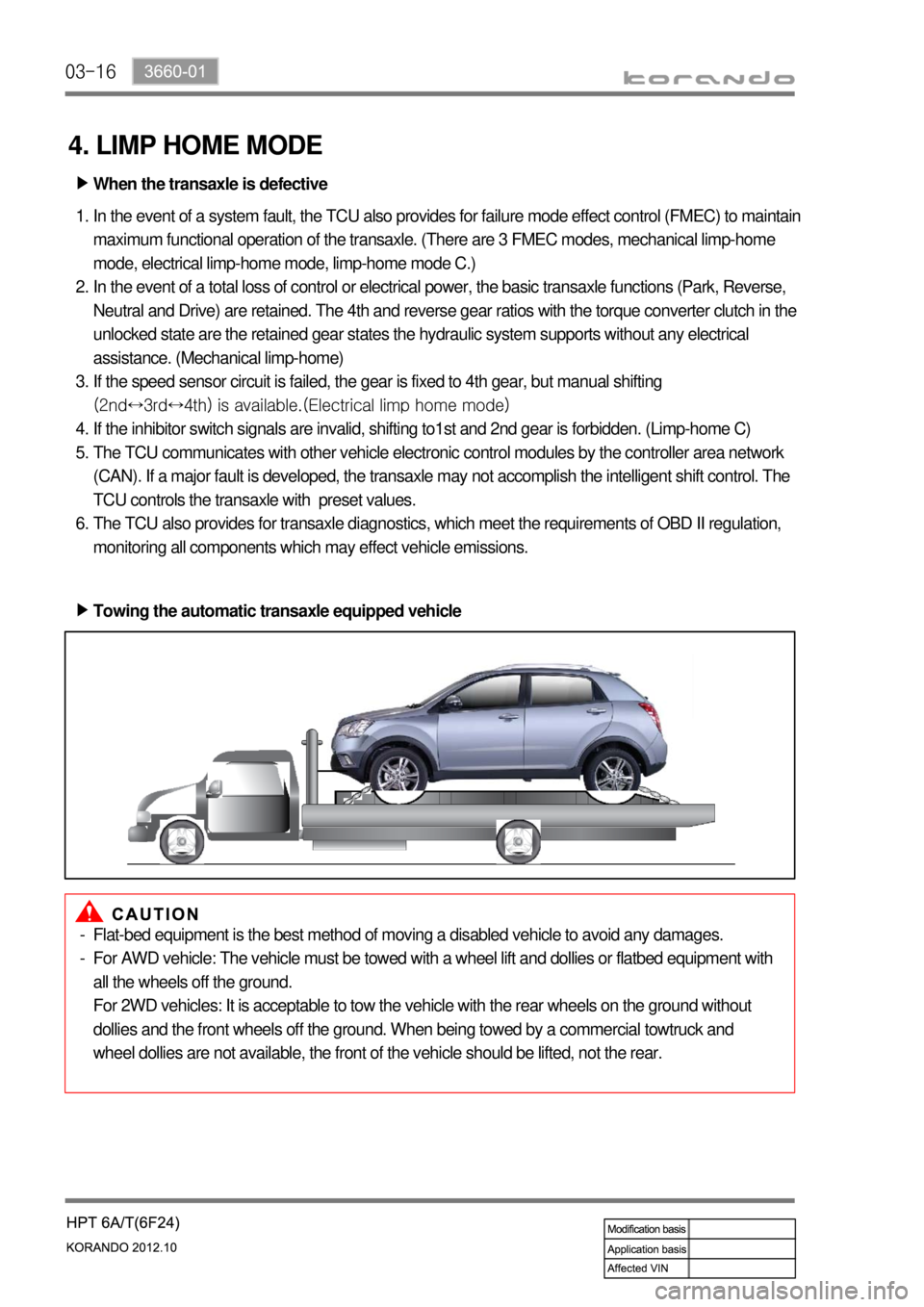
Towing the automatic transaxle equipped vehicle ▶
Flat-bed equipment is the best method of moving a disabled vehicle to avoid any damages.
For AWD vehicle: The vehicle must be towed with a wheel lift and dollies or flatbed equipment with
all the wheels off the ground.
For 2WD vehicles: It is acceptable to tow the vehicle with the rear wheels on the ground without
dollies and the front wheels off the ground. When being towed by a commercial towtruck and
wheel dollies are not available, the front of the vehicle should be lifted, not the rear. -
-
Page 1032 of 1082

02-16
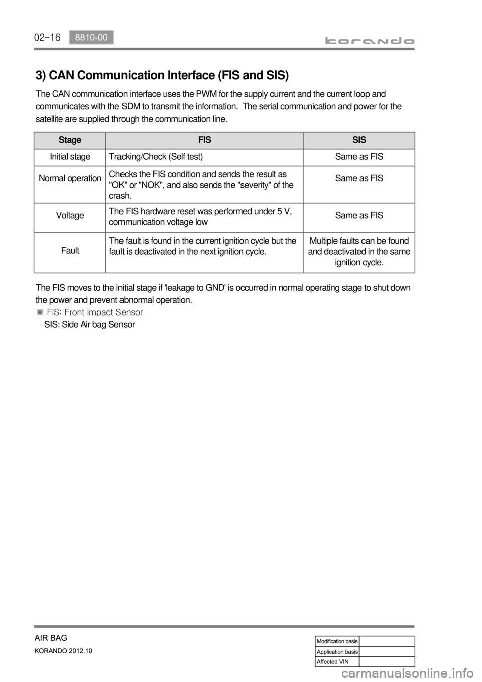
3) CAN Communication Interface (FIS and SIS)
The CAN communication interface uses the PWM for the supply current and the current loop and
communicates with the SDM to transmit the information. The serial communication and power for the
satellite are supplied through the communication line.
Stage FIS SIS
Initial stage Tracking/Check (Self test) Same as FIS
Normal operation Checks the FIS condition and sends the result as
"OK" or "NOK", and also sends the "severity" of the
crash. Same as FIS
Voltage The FIS hardware reset was performed under 5 V,
communication voltage low Same as FIS
Fault The fault is found in the current ignition cycle but the
fault is deactivated in the next ignition cycle. Multiple faults can be found
and deactivated in the same
ignition cycle.
The FIS moves to the initial stage if 'leakage to GND' is occurred in normal operating stage to shut down
the power and prevent abnormal operation.
※ FIS: Front Impact Sensor
SIS: Side Air bag Sensor
Page 1040 of 1082

04-37340-00
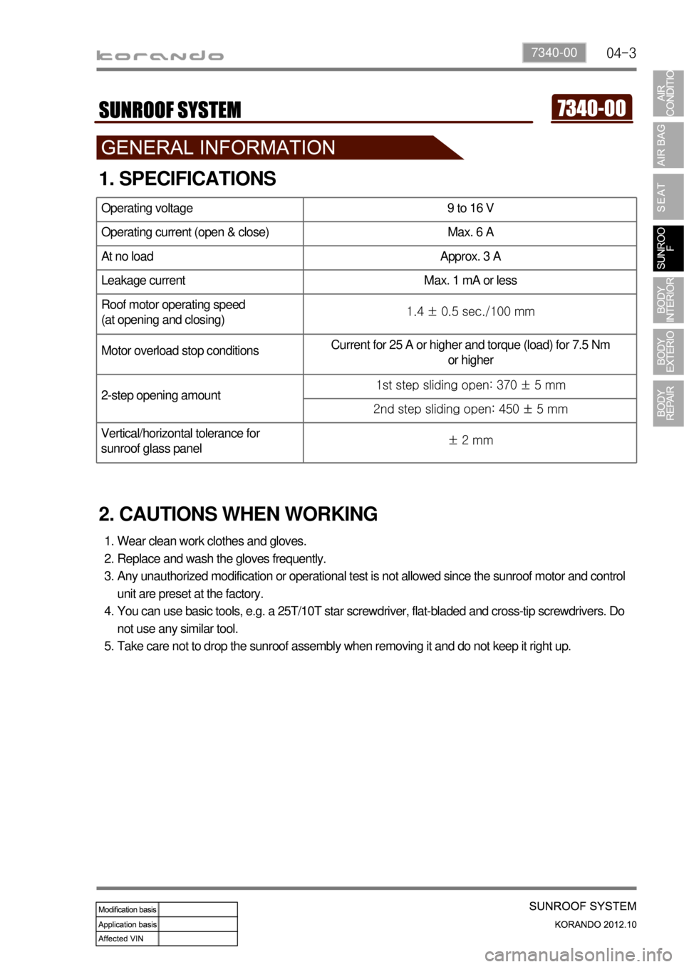
1. SPECIFICATIONS
2. CAUTIONS WHEN WORKING
Wear clean work clothes and gloves.
Replace and wash the gloves frequently.
Any unauthorized modification or operational test is not allowed since the sunroof motor and control
unit are preset at the factory.
You can use basic tools, e.g. a 25T/10T star screwdriver, flat-bladed and cross-tip screwdrivers. Do
not use any similar tool.
Take care not to drop the sunroof assembly when removing it and do not keep it right up. 1.
2.
3.
4.
5.
Operating voltage 9 to 16 V
Operating current (open & close) Max. 6 A
At no load Approx. 3 A
Leakage current Max. 1 mA or less
Roof motor operating speed
(at opening and closing)1.4 ± 0.5 sec./100 mm
Motor overload stop conditionsCurrent for 25 A or higher and torque (load) for 7.5 Nm
or higher
2-step opening amount1st step sliding open: 370 ± 5 mm
2nd step sliding open: 450 ± 5 mm
Vertical/horizontal tolerance for
sunroof glass panel± 2 mm
Page 1047 of 1082

04-10
4. ZERO POINT SETTING
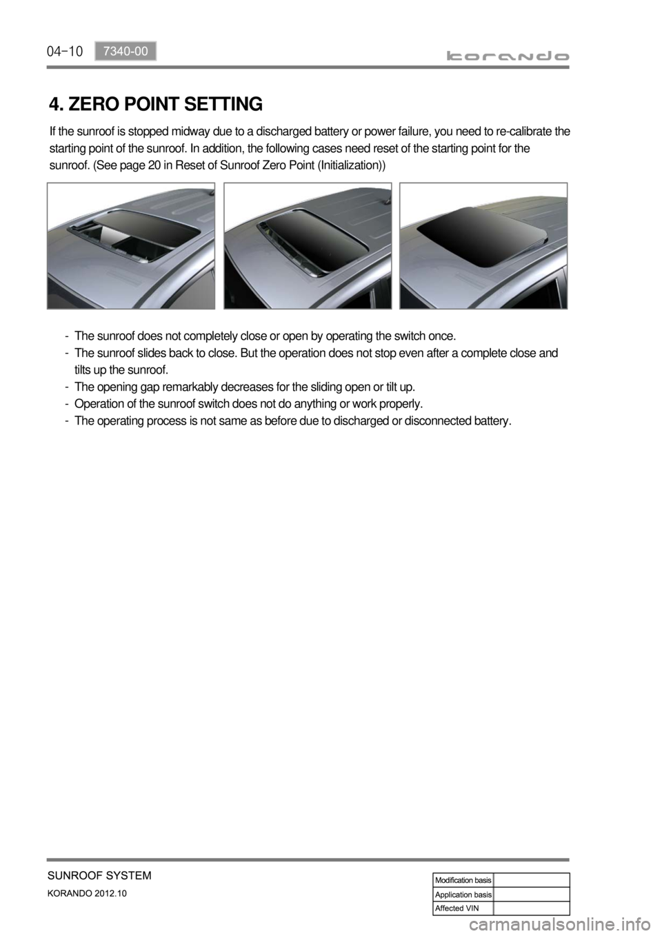
If the sunroof is stopped midway due to a discharged battery or power failure, you need to re-calibrate the
starting point of the sunroof. In addition, the following cases need reset of the starting point for the
sunroof. (See page 20 in Reset of Sunroof Zero Point (Initialization))
The sunroof does not completely close or open by operating the switch once.
The sunroof slides back to close. But the operation does not stop even after a complete close and
tilts up the sunroof.
The opening gap remarkably decreases for the sliding open or tilt up.
Operation of the sunroof switch does not do anything or work properly.
The operating process is not same as before due to discharged or disconnected battery. -
-
-
-
-