Page 759 of 1082

07-6
(1) Headlamp
2) Operation
High-beam/low-beam
Most of the functions of the headlamp is controlled by the multifunction switch. The functions performed by
REKES or SMART key are controlled by the BCM.
The BCM controls the headlamp and tail lamp by using the data sent through the LIN communication from
the automatic light sensor when the multifunction switch is in AUTO position.
Control by BCM ▶
Coming home lighting control 1.
The headlamp is illuminated for 30 sec. when the ignition switch is turned on and then off with the
multifunction switch in ON or AUTO.
The headlamp is turned off right after the ignition is turned on. And when all the doors (including
tailgate) are closed the headlamp is illuminated for 30 sec.; and all the doors are open, the headlamp
is illuminated for 3 minutes.
This function can be deactivated or activated with a diagnostic equipment. -
-
-
DRL (Day Time Running Light) ▶
DRL is the function to turn on the high beam and tail lamp without any intervention from the light
switch. DRL turns off the lamps when turning off the light switch. This is an additional safety device to
prevent the accident.
Page 773 of 1082
08-77810-00
2. RAIN SENSING SYSTEM
In the rain sensing wiper operation system, the rain sensing unit only sends the information about the
amount of rain drops to the BCM, and it does not operate the wiper directly. The wiper and washer are
controlled by the BCM according to the driver's choice.
Rain sensing unitMultifunction wiper switch
AUTO and sensitivity control
This sensor emits infrared rays through LED
and then detects the amount of rain drops
by receiving the rays reflected off the
sensing section (rain sensor mounting
section on the windshield) with photodiode.AUTO: Wiper operates automatically by rain
sensor
FAST <-------> SLOW:
Auto delay/auto speed control.
A position that can control the sensitivity for
the amount of rains on the windshield and
transmit the wiping request signal
accordingly.
Rain sensor emitter lens
Auto light sensor sensing
portion
Page 850 of 1082

02-16
3) Shift Map Selection
The driver can manually select between normal (S) and winter modes (W) via the mode switch.
Depending on the transaxle temperature, uphill and downhill grades and altitude, shift maps will be
selected by the TCU to suit the driving conditions. The following maps are available.
Standard (Normal) Mode ▶
Normal Mode is selected when the lever is in the D position with the mode switch in the normal (S)
position and the transaxle is within normal temperature ranges. Shift schedule points are optimised for
fuel efficiency and general driving conditions.
Uphill and Downhill Mode ▶
In this mode, depending on the load of the vehicle, adaptive shift maps are selected to progressively
adjust the shift points and torque converter lock points.
Altitude Mode ▶
Shift points are automatically adjusted at higher altitudes to compensate for changes in engine torque
where the torque produced by the engine is greatly reduced by the effects of reduced barometric
pressure and temperature.
Winter (W) Mode ▶
When winter mode is selected, starting in second gear is facilitated and the WINTER mode indicator
light is switched ON. To prevent wheel spin on slippery surfaces, the transmission will not allow first gear
unless manually overridden.
Warm up Schedule ▶
<007c009a008c008b0047009b00a000970090008a00880093009300a00047009e008f008c00950047009b009900880095009a0088009f0093008c0047008d0093009c0090008b0047009b008c00940097008c00990088009b009c0099008c00470090009a00
470089008c00930096009e00470059005700b6006a0055>
The torque converter will not lock-up below 20°C to assist in transaxle warm-up.
Hot Mode ▶
<007b008f008c0047008f0096009b004700940096008b008c00470090009a0047009700990096008e0099008c009a009a0090009d008c009300a0004700880097009700930090008c008b00470089008c009b009e008c008c00950047009b008c0094009700
8c00990088009b009c0099008c009a00470096008d00470058>10° ~ 200°C. The torque
converter lock-up is increased to prevent heat generation by the torque converter.
Activation of the hot mode inhibits other transmission performance features including uphill and downhill
compensation and altitude compensation. Some degradation in shift feel may be experienced as the
torque converter is not unlocked during shifting.
Cruise Control Mode ▶
When cruise control is activated the engine ECU may request the transaxle to downshift under trailing
throttle conditions to increase engine braking.
Above 110℃the electrical radiator fans are switch ON
Above 130℃the engine torque will be reduced and the W light on the instrument cluster will flash
Above 200℃the transaxle will neutralise until the fluid tem
perature falls below 200°C as a final
protection.
Page 877 of 1082

03-173660-01
5. TRANSAXLE ELECTRONIC CONTROL SYSTEM
1) General Information
The transmission control unit (TCU) and its input/output network control the following transmission
operations:
Shift timing
Line pressure
Clutch pressure (shift feel)
Torque converter clutch -
-
-
-
also uses these signals when determining transaxle operating strategy. Using all of these input signals,
the TCU can determine when the time and conditions are right for a shift, or when to apply or release the
torque converter clutch. It will also determine the pressure needed to optimise shift feel.
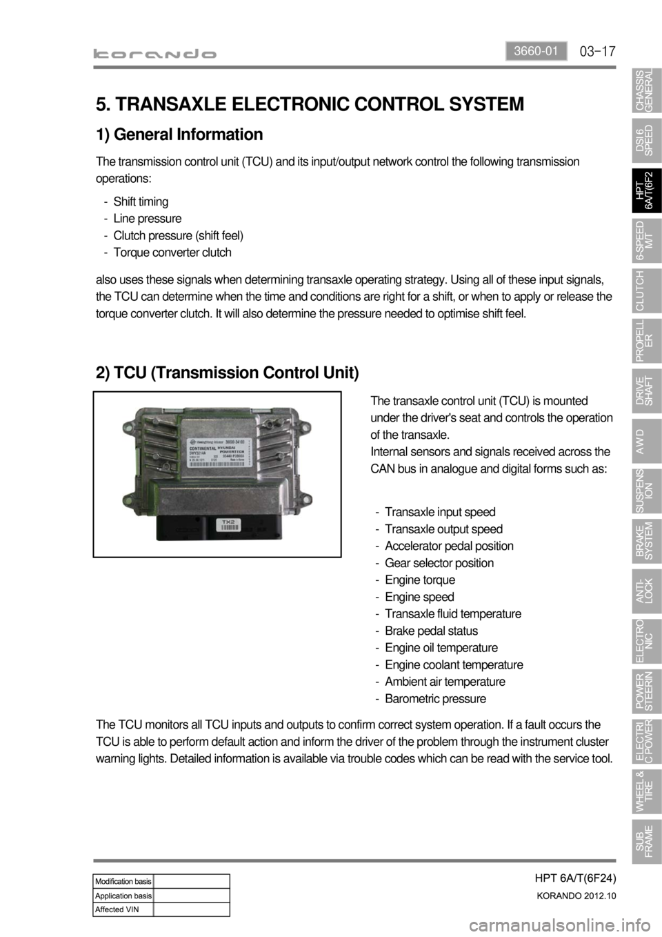
2) TCU (Transmission Control Unit)
The transaxle control unit (TCU) is mounted
under the driver's seat and controls the operation
of the transaxle.
Internal sensors and signals received across the
CAN bus in analogue and digital forms such as:
Transaxle input speed
Transaxle output speed
Accelerator pedal position
Gear selector position
Engine torque
Engine speed
Transaxle fluid temperature
Brake pedal status
Engine oil temperature
Engine coolant temperature
Ambient air temperature
Barometric pressure -
-
-
-
-
-
-
-
-
-
-
-
The TCU monitors all TCU inputs and outputs to confirm correct system operation. If a fault occurs the
TCU is able to perform default action and inform the driver of the problem through the instrument cluster
warning lights. Detailed information is available via trouble codes which can be read with the service tool.
Page:
< prev 1-8 9-16 17-24