Page 841 of 1082

02-73680-01
3. TIGHTENING TORQUE
DescriptionsSize x
NumbersTightening torque
(Nm)
Automatic transaxleEngine side mounting bolt 17 mm X 4 85.0 to 100
Oil pan and engine side mounting
bolt14 mm X 4 56.0 to 62.0
Oil filler plug 16 mm 25.0 to 30.0
Oil drain plug Hexagon 5 mm 25.0 to 30.0
Valve bodyAssembly mounting screw T30 mm X 9 16.0
Oil pan bolt 10 mm X 15 7.0 to 8.0
VBS screw T30 mm 4.0
Valve body screw T30 mm X 25 16.0
Torque converter Mounting bolt 13 mm X 6 40.0 to 42.0
CableLink nut (switch side) 13 mm X 1 13.7 to 19.6
Link nut (cable side) 12 mm X 1 14.7 to 22.5
Mounting nut (floor side) 12 mm X 1 17.6 to 21.6
Mounting nut (dash panel side) 12 mm X 2 17.6 to 21.6
TGS lever Mounting nut 12 mm X 4 17.6 to 21.6
TCU Mounting nut 8 mm X 2 5.0 to 6.0
Inhibitor switch Mounting nut 12 mm X 2 3.9 to 7.8
Transaxle bracketLeft bracket 17 mm X 3 85.0 to 100
Right bracket 17 mm X 4 85.0 to 100
Upper bracket 17 mm X 4 85.0 to 100
Oil cooler pipeMounting bolt 10 mm X 2 Max.: 13.0
Bracket mounting bolt 10 mm X 1 13.0
Page 842 of 1082

02-8
1. OVERVIEW
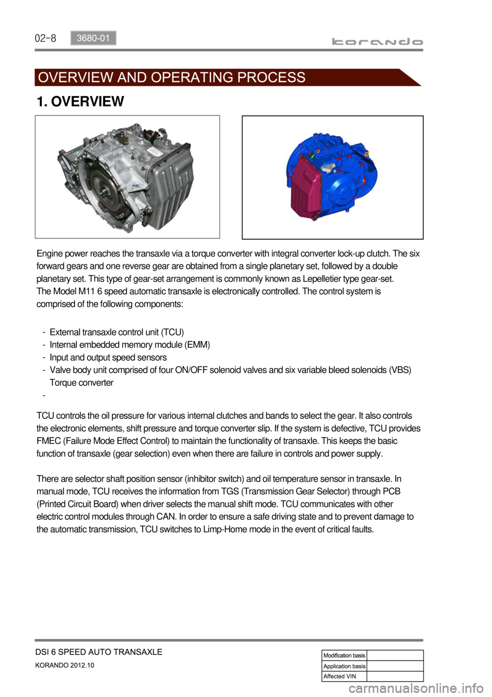
Engine power reaches the transaxle via a torque converter with integral converter lock-up clutch. The six
forward gears and one reverse gear are obtained from a single planetary set, followed by a double
planetary set. This type of gear-set arrangement is commonly known as Lepelletier type gear-set.
The Model M11 6 speed automatic transaxle is electronically controlled. The control system is
comprised of the following components:
External transaxle control unit (TCU)
Internal embedded memory module (EMM)
Input and output speed sensors
Valve body unit comprised of four ON/OFF solenoid valves and six variable bleed solenoids (VBS)
Torque converter -
-
-
-
-
TCU controls the oil pressure for various internal clutches and bands to select the gear. It also controls
the electronic elements, shift pressure and torque converter slip. If the system is defective, TCU provides
FMEC (Failure Mode Effect Control) to maintain the functionality of transaxle. This keeps the basic
function of transaxle (gear selection) even when there are failure in controls and power supply.
There are selector shaft position sensor (inhibitor switch) and oil temperature sensor in transaxle. In
manual mode, TCU receives the information from TGS (Transmission Gear Selector) through PCB
(Printed Circuit Board) when driver selects the manual shift mode. TCU communicates with other
electric control modules through CAN. In order to ensure a safe driving state and to prevent damage to
the automatic transmission, TCU switches to Limp-Home mode in the event of critical faults.
Page 843 of 1082

02-93680-01
2. FEATURES
1) Advantages
Early Downshift with Hard Braking and Skip Shifts ▶
When heavy braking is detected, the transaxle downshifts early and skips gears to provide increased
engine braking to provide gear selection for tip-in.
Gear Hold going Uphill/Downhill ▶
If the accelerator pedal is released when traveling uphill, upshifts are prevented to reduce busyness on
grades. If the accelerator pedal is released when traveling downhill, upshifts are prevented to enhance
engine braking.
Drive and Reverse Engagement ▶
A soft engagement feature avoids harsh take up of drive when selecting Drive or Reverse. This is
achieved by limiting engine speed and engine torque which results in a rapid, but progressive
engagement of either Drive or Reverse when moving from the Park or Neutral positions. Drive and
Reverse engagements from either Park or Neutral are performed in less than 2.2 seconds. There is no
drive engagement prevention strategy implemented on the transaxle system as there is sufficient engine
strategy to protect the system. However, reverse engagement is prevented until engine speed is less
than 1,400 rpm and the accelerator pedal position is less than 12% and vehicle speed is less than 10
km/h.
Converter Clutch Lock-Up In All Gears ▶
The transaxle features converter clutch lock-up in all gears. This feature provides improved fuel economy
and vehicle performance. It also improves transaxle cooling efficiency when towing heavy loads at low
speeds, e.g. in city driving or hill terrain.
Embedded Memory Module (EMM) ▶
The embedded memory module (EMM) is
matched to the transaxle’s valve bodies during
transaxle assembly to ensure refined shift quality.
The EMM is used to store data such as valve body
calibration data and valve body serial number.
Upon installation, the TCU will download the data
from the EMM and utilize this data in the operation
of the transaxle.
Page 867 of 1082
03-73660-01
4. COMPONENTS
HPT 6A/T (6F24)
One-way clutchTorque converter
(with slip lockup)
Oil pumpHarness
Valve bodySide gearDriven gear
Page 868 of 1082

03-8
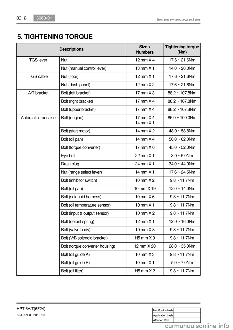
Automatic transaxle Bolt (engine) 17 mm X 4
14 mm X 1 85.0 ~ 100.0Nm
Bolt (start motor) 14 mm X 2 48.0 ~ 58.8Nm
Bolt (oil pan) 14 mm X 4 56.0 ~ 62.0Nm
Bolt (torque converter) 17 mm X 6 45.0 ~ 52.0Nm
Eye bolt 22 mm X 1 3.0 ~ 5.0Nm
Drain plug 24 mm X 1 34.0 ~ 44.0Nm
Nut (range select lever) 14 mm X 1 17.6 ~ 24.5Nm
Bolt (inhibitor switch) 10 mm X 2 9.8 ~ 11.7Nm
Bolt (oil pan) 10 mm X 19 12.0 ~ 14.0Nm
Bolt (solenoid harness) 10 mm X 6 9.8 ~ 11.7Nm
Bolt (oil temperature sensor) 10 mm X 1 9.8 ~ 11.7Nm
Bolt (input & output sensor) 10 mm X 2 9.8 ~ 11.7Nm
Bolt (detent spring) 12 mm X 1 12.0 ~ 16.0Nm
Bolt (valve body) 10 mm X 8 9.8 ~ 11.7Nm
Bolt (V/B solenoid bracket) H5 mm X 9 9.8 ~ 11.7Nm
Bolt (torque converter housing) 12 mm X 20 28.0 ~ 35.0Nm
Bolt (oil guide A) 10 mm X 3 9.8 ~ 11.7Nm
Bolt (oil guide B) 10 mm X 1 5.0 ~ 7.0Nm
Bolt (oil filter) H5 mm X 2 9.8 ~ 11.7Nm
5. TIGHTENING TORQUE
DescriptionsSize x
NumbersTightening torque
(Nm)
TGS lever Nut 12 mm X 4 17.6 ~ 21.6Nm
Nut (manual control lever) 13 mm X 1 14.0 ~ 20.0Nm
Nut (floor) 12 mm X 1 17.6 ~ 21.6Nm
Nut (dash panel) 12 mm X 2 17.6 ~ 21.6Nm
A/T bracket Bolt (left bracket) 17 mm X 3 88.2 ~ 107.8Nm
Bolt (right bracket) 17 mm X 4 88.2 ~ 107.8Nm
Bolt (upper bracket) 17 mm X 4 88.2 ~ 107.8Nm
TGS lever
TGS cable
Page:
< prev 1-8 9-16 17-24