Page 871 of 1082

03-113660-01
1. OVERVIEW
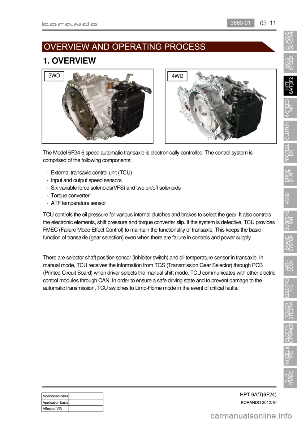
2WD4WD
The Model 6F24 6 speed automatic transaxle is electronically controlled. The control system is
comprised of the following components:
External transaxle control unit (TCU)
Input and output speed sensors
Six variable force solenoids(VFS) and two on/off solenoids
Torque converter
ATF temperature sensor -
-
-
-
-
TCU controls the oil pressure for various internal clutches and brakes to select the gear. It also controls
the electronic elements, shift pressure and torque converter slip. If the system is defective, TCU provides
FMEC (Failure Mode Effect Control) to maintain the functionality of transaxle. This keeps the basic
function of transaxle (gear selection) even when there are failure in controls and power supply.
There are selector shaft position sensor (inhibitor switch) and oil temperature sensor in transaxle. In
manual mode, TCU receives the information from TGS (Transmission Gear Selector) through PCB
(Printed Circuit Board) when driver selects the manual shift mode. TCU communicates with other electric
control modules through CAN. In order to ensure a safe driving state and to prevent damage to the
automatic transmission, TCU switches to Limp-Home mode in the event of critical faults.
Page 873 of 1082
03-133660-01
2) Transaxle Cooling
The transaxle cooling system ensures rapid warm-up and constant operating temperature resulting in
reduced fuel consumption and refined shift quality.
It also includes a cooler by-pass within the hydraulic system to allow sufficient lubrication to the transaxle
drivetrain in the event of a blockage in the transaxle cooler.
3) Shift Strategy
Gear Change ▶
Transaxle gear change is controlled by the
TCU. The TCU receives inputs from various
engine and vehicle sensors to select shift
schedules and to control the shift feel and
torque converter clutch (TCC) operation at each
gear change.
Coast down ▶
Coast down down shifts occur at 0% pedal
when the vehicle is coasting down to a stop.
Torque Demand ▶
Torque demand down shifts occur
(automatically) when the driver demand for
torque is greater than the engine can provide at
that gear ratio. If applied, the transaxle will
disengage the TCC to provide added
acceleration.
Page 876 of 1082

03-16
4. LIMP HOME MODE
When the transaxle is defective ▶
In the event of a system fault, the TCU also provides for failure mode effect control (FMEC) to maintain
maximum functional operation of the transaxle. (There are 3 FMEC modes, mechanical limp-home
mode, electrical limp-home mode, limp-home mode C.)
In the event of a total loss of control or electrical power, the basic transaxle functions (Park, Reverse,
Neutral and Drive) are retained. The 4th and reverse gear ratios with the torque converter clutch in the
unlocked state are the retained gear states the hydraulic system supports without any electrical
assistance. (Mechanical limp-home)
If the speed sensor circuit is failed, the gear is fixed to 4th gear, but manual shifting
<004f00590095008b02e9005a0099008b02e9005b009b008f005000470090009a00470088009d008800900093008800890093008c0055004f006c0093008c008a009b00990090008a00880093004700930090009400970047008f00960094008c0047009400
96008b008c0050>
If the inhibitor switch signals are invalid, shifting to1st and 2nd gear is forbidden. (Limp-home C)
The TCU communicates with other vehicle electronic control modules by the controller area network
(CAN). If a major fault is developed, the transaxle may not accomplish the intelligent shift control. The
TCU controls the transaxle with preset values.
The TCU also provides for transaxle diagnostics, which meet the requirements of OBD II regulation,
monitoring all components which may effect vehicle emissions. 1.
2.
3.
4.
5.
6.
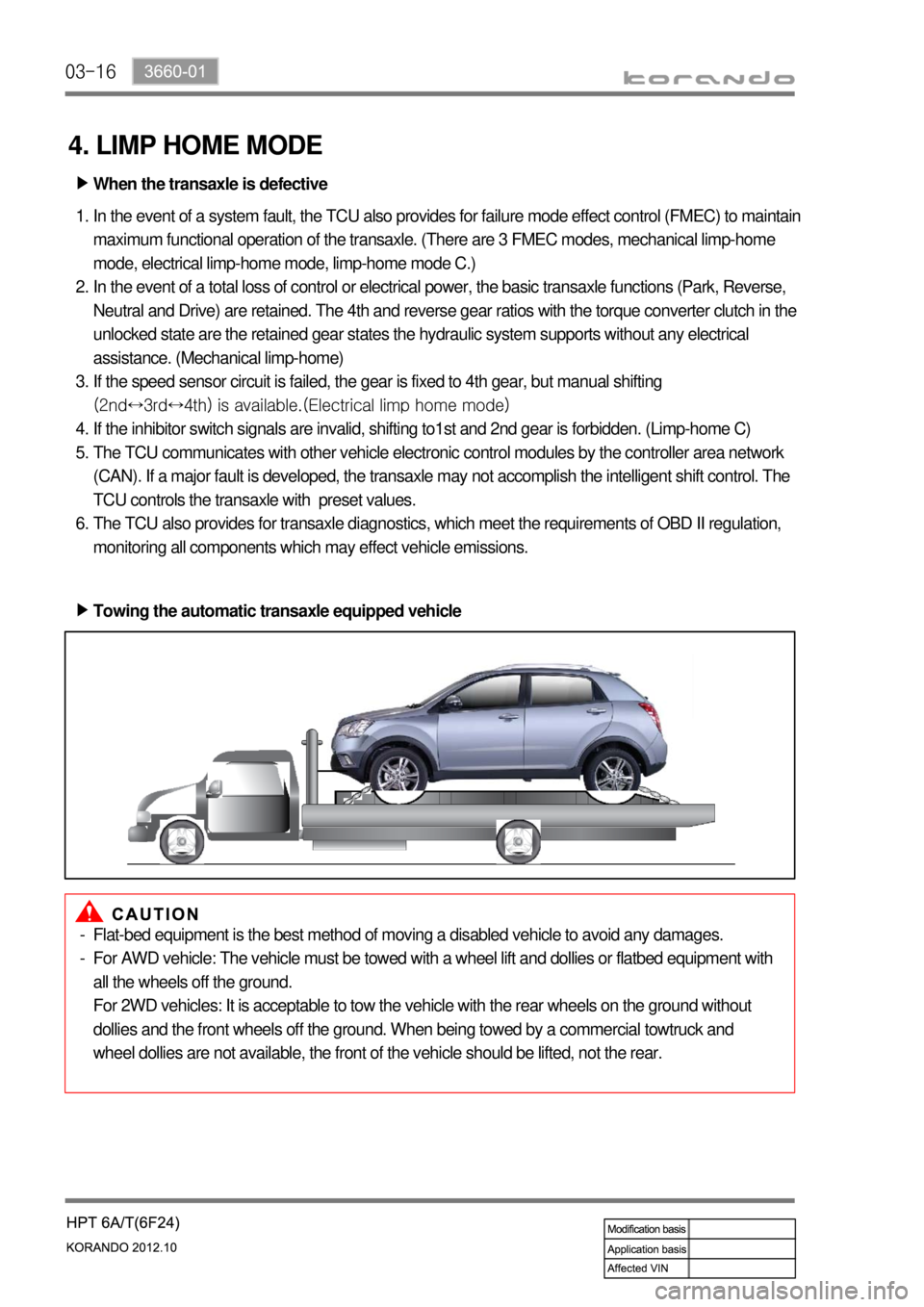
Towing the automatic transaxle equipped vehicle ▶
Flat-bed equipment is the best method of moving a disabled vehicle to avoid any damages.
For AWD vehicle: The vehicle must be towed with a wheel lift and dollies or flatbed equipment with
all the wheels off the ground.
For 2WD vehicles: It is acceptable to tow the vehicle with the rear wheels on the ground without
dollies and the front wheels off the ground. When being towed by a commercial towtruck and
wheel dollies are not available, the front of the vehicle should be lifted, not the rear. -
-
Page 877 of 1082

03-173660-01
5. TRANSAXLE ELECTRONIC CONTROL SYSTEM
1) General Information
The transmission control unit (TCU) and its input/output network control the following transmission
operations:
Shift timing
Line pressure
Clutch pressure (shift feel)
Torque converter clutch -
-
-
-
also uses these signals when determining transaxle operating strategy. Using all of these input signals,
the TCU can determine when the time and conditions are right for a shift, or when to apply or release the
torque converter clutch. It will also determine the pressure needed to optimise shift feel.
2) TCU (Transmission Control Unit)
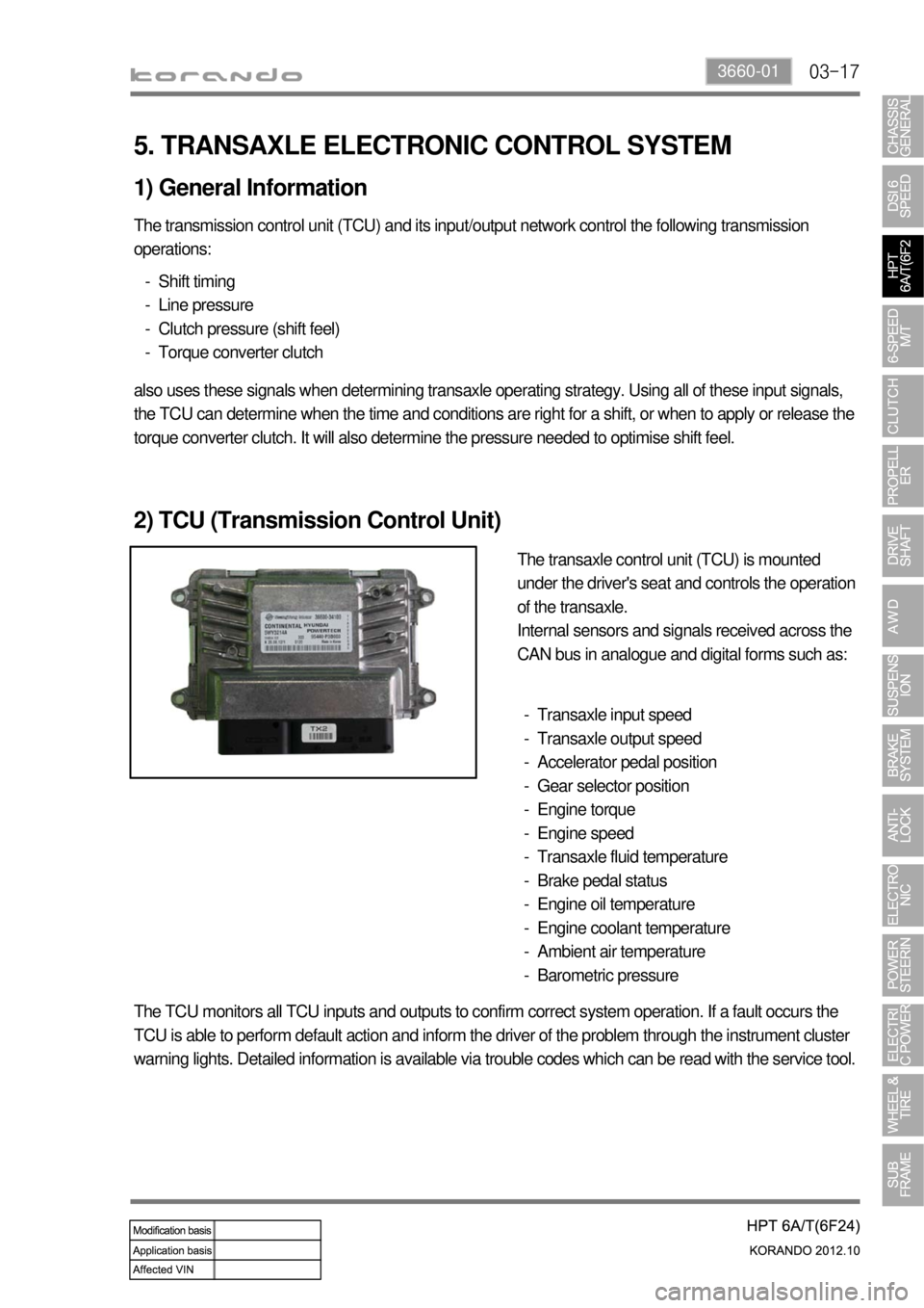
The transaxle control unit (TCU) is mounted
under the driver's seat and controls the operation
of the transaxle.
Internal sensors and signals received across the
CAN bus in analogue and digital forms such as:
Transaxle input speed
Transaxle output speed
Accelerator pedal position
Gear selector position
Engine torque
Engine speed
Transaxle fluid temperature
Brake pedal status
Engine oil temperature
Engine coolant temperature
Ambient air temperature
Barometric pressure -
-
-
-
-
-
-
-
-
-
-
-
The TCU monitors all TCU inputs and outputs to confirm correct system operation. If a fault occurs the
TCU is able to perform default action and inform the driver of the problem through the instrument cluster
warning lights. Detailed information is available via trouble codes which can be read with the service tool.
Page 924 of 1082
09-4
3) Parts Arrangement
Part nameVehicle with
CBSVehicle with ABS/EBDVehicle with
ESP
HECU
Not appliedAppliedApplied Front wheel speed sensor
Rear wheel speed sensor
ABS warning lamp
EBD indicator
Longitudinal G sensor 2WD: N/A, 4WD: Applied Not applied
Sensor cluster
(Yaw rate sensor,
lateral/longitudinal G sensor)
Not applied Applied
ESP indicator
ESP OFF switch and warning
lamp
Steering wheel angle sensor
Page 925 of 1082
09-54850-00
F. Front/rear wheel speed sensor
Front/rear-4WD Rear-2WDH. Parking brake
A. Meter cluster-ABS, EBD, ESP
indicator/warning lampB. Master cylinder and
boosterC. HECU
G. Brake pedal
4) Component
ABS warning lamp
ESP indicator
D. Front brake
assembly
E. Rear brake
assembly
Disc
Disc
Parking brake
warning lamp
Caliper
Caliper
Page 926 of 1082

09-6
2. SPECIFICATION (DSL ONLY)
Unit Description Specification
Front brake Type Ventilated disc
Outer diameter of discØ298 mm
Inner diameter of caliper cylinderØ43.0 x 2 mm
Thickness of disc 26 mm (wear limit: 24 mm)
Thickness of brake pad 10.5 mm (wear limit: 2 mm)
Pad wear indicator Mechanical type
Rear brake Type Solid disc
Outer diameter of disc2WD: Ø262 mm, 4WD: Ø284 mm
Thickness of disc 10 mm (wear limit: 8.4 mm)
Thickness of brake pad 10 mm (wear limit: 2 mm)
Pad wear indicator Mechanical type
Brake booster Type Vacuum assist type
Size8” + 9” (Tandem)
Master cylinder Type Tandem (level sensor installed)
Inner diameter of cylinderØ25.4 mm
Brake pedal Maximum operating stroke140 ± 3 mm
Pedal ratio 3.8 : 1
Free play 3 to 10 mm
Parking brake Type Mechanically expanded rear lining
Operating type Hand operated type
Inner diameter of drum2WD: Ø168 mm, 4WD: Ø190 mm
Brake oil Specification DOT 4
Capacity 0.7 to 0.8 liters
Service interval for brake fluid: Change every other year.
Page 934 of 1082
10-34890-00
1. SPECIFICATION
Unit DescriptionSpecification
ABS ESP
HECUClock frequency 32 MHz 50 MHz
Memory 128 KB 512 KB
Switch Orifice Orifice
Wheel speed
sensorABS / ESP CBS
Operating temperature- 40°C to 150°C - 40°C to 150°C
- 40°C to 115°C - 40°C to 115°C
Operating frequency 1 to 2,500 Hz 1 to 8,000 Hz
Operating voltage 4.5 to 16 V 3.3 to 18 V
G-sensor ABS CBS / ESP
Operating voltage 4.75 to 5.25 V N/A
Operating temperature- 30°C to 85°C
Operating range -1.5 to 1.5 g
Output voltage 0.5 to 4.5 V