Page 1006 of 1082
01-56810-00
2) Manual A/C Controller
Manual air conditioner controller
Previous Current
The driving circuit for the ambient temperature sensor is added to the manual air conditioner controller
for ambient temperature display on the instrument cluster.
Connector added
Pin No. Function
B1 -
B2 -
B3 -
B4 Water temp. signal
B5 -
B6 -
B7 -
B8 -
B9 -
B10 Sun-load sensor signal
B11 Ambient temp. sensor signal
B12 -
Page 1008 of 1082
01-76810-00
FATC Incar sensor
Refrigerant pressure
sensor
Ambient temperature
sensor
Sun-load sensor
Engine ECU
Page 1010 of 1082
01-96810-00
Incar sensor
This sensor detects the inside temperature and
installed in PCB.Face-Level
(vent mode)Face/Foot-Level
(bi-level mode)Foot-Level
(foot mode)
Foot/Defrost-level
(foot/defrost mode)
Defroster switch
Use this switch to remove for or
ice from the windshield. When
choosing this mode, the airflow
direction will be changed to the
windshield and side glasses, the
air conditioner operates
automatically, and fresh air
comes in. The air flow direction can be controlled by turning the dial. -
Airflow is changed
automatically according to the
setting temperature.
Fan speed dial
Manual control
Fan speed is manually controlled b
y
this dial. The increment is 1℃.
Auto control
Fan speed is automatically
controlled by temperature setting.
The blower motor operates in a
stepless mode. -
-
A/C switch
When pressing this switch,
the air conditioner operates
in manual mode and A/C
ON indicator comes on.
Fan speed dial ▶Mode dial ▶
Page 1019 of 1082
02-38810-00
1. SPECIFICATIONS
Operating voltage 9 to 16 V
System diagnosis and SDM self diagnosis voltage 9 to 16 V
Ignition voltage for side air bag and pretensioner 9 to 16 V
Communication voltage for front impact sensor 9 to 16 V
Communication voltage for side impact sensor 9 to 16 V
Operating temperature -40℃ ~ 85℃
Storage temperature -40℃ ~ 90℃
Ignition temperature -30℃ ~ 85℃
Overvoltage protection 24 V
2. MAJOR REPLACEMENT PARTS AFTER AIR BAG
DEPLOYMENT
A. In Case Of Front Air Bag Deployment
Air bag unit and its wirings (including connectors), seat belt pretensioner and its wirings (including
connectors), all front air bags, instrument panel, front impact sensor and other damaged components
B. In Case Of Curtain Air Bag Deployment
Deployed curtain air bag, air bag unit and its wiring (including connector), impact G sensor assembly for
curtain air bag, damaged trim, seat and roof headlining
Page 1020 of 1082

02-4
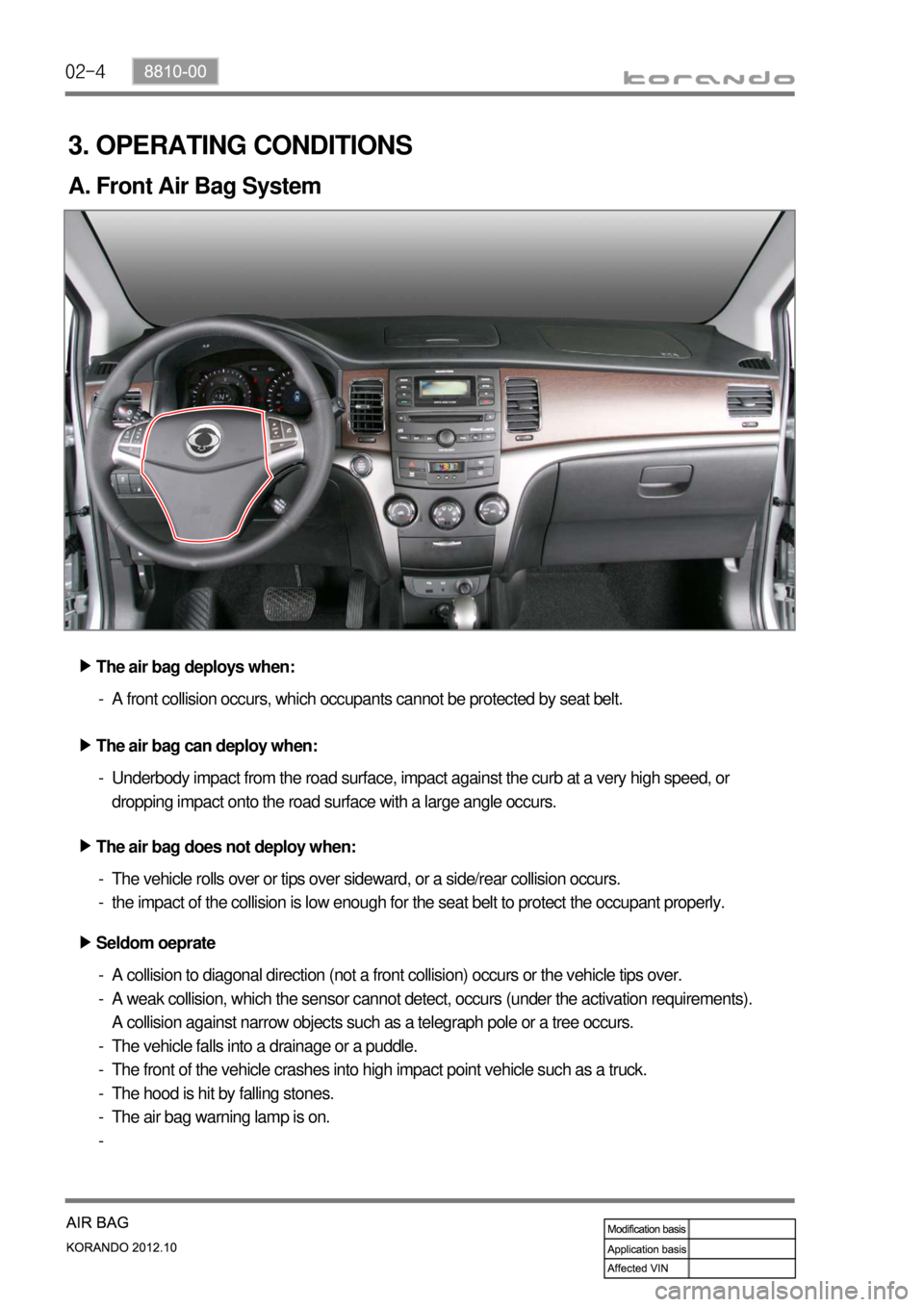
3. OPERATING CONDITIONS
A. Front Air Bag System
The air bag does not deploy when: ▶The air bag deploys when: ▶
The air bag can deploy when: ▶A front collision occurs, which occupants cannot be protected by seat belt. -
The vehicle rolls over or tips over sideward, or a side/rear collision occurs.
the impact of the collision is low enough for the seat belt to protect the occupant properly. -
-Underbody impact from the road surface, impact against the curb at a very high speed, or
dropping impact onto the road surface with a large angle occurs. -
Seldom oeprate ▶
A collision to diagonal direction (not a front collision) occurs or the vehicle tips over.
A weak collision, which the sensor cannot detect, occurs (under the activation requirements).
A collision against narrow objects such as a telegraph pole or a tree occurs.
The vehicle falls into a drainage or a puddle.
The front of the vehicle crashes into high impact point vehicle such as a truck.
The hood is hit by falling stones.
The air bag warning lamp is on. -
-
-
-
-
-
-
Page 1027 of 1082
02-118810-00
Inflatable curtain air bag module
Side air bag sensor
assembly
Front impact sensor
assembly
Air bag warning lamp
(IP)
Height adjuster
Page 1029 of 1082

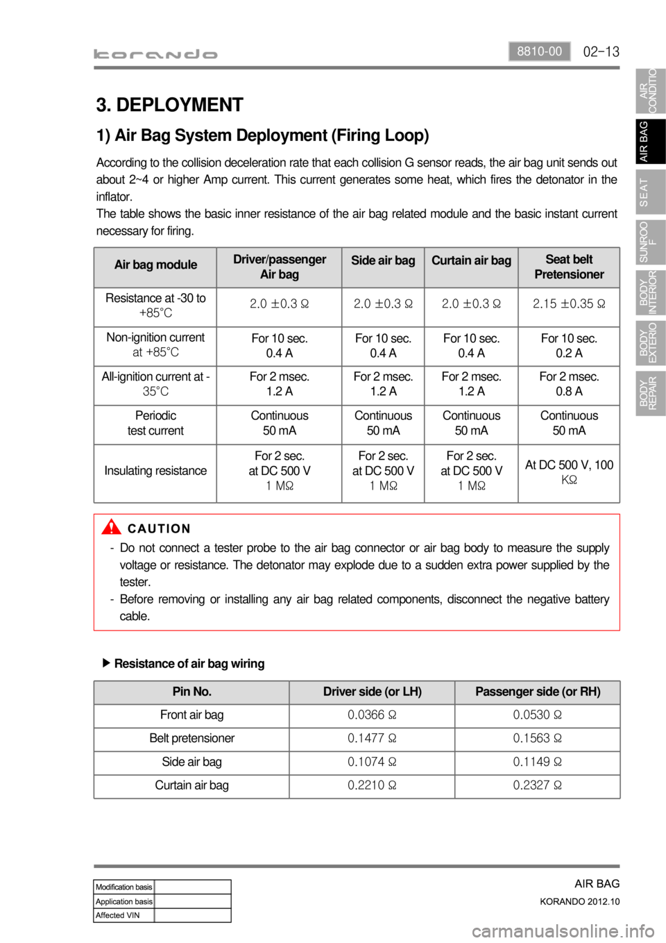
02-138810-00
Air bag moduleDriver/passenger
Air bagSide air bag Curtain air bagSeat belt
Pretensioner
Resistance at -30 to
+85°C2.0 ±0.3 Ω 2.0 ±0.3 Ω 2.0 ±0.3 Ω 2.15 ±0.35 Ω
Non-ignition current
at +85°CFor 10 sec.
0.4 A For 10 sec.
0.4 AFor 10 sec.
0.4 AFor 10 sec.
0.2 A
All-ignition current at -
35°CFor 2 msec.
1.2 AFor 2 msec.
1.2 AFor 2 msec.
1.2 AFor 2 msec.
0.8 A
Periodic
test currentContinuous
50 mAContinuous
50 mAContinuous
50 mAContinuous
50 mA
Insulating resistanceFor 2 sec.
at DC 500 V
1 MΩFor 2 sec.
at DC 500 V
1 MΩFor 2 sec.
at DC 500 V
1 MΩ
At DC 500 V, 100
KΩ
3. DEPLOYMENT
According to the collision deceleration rate that each collision G sensor reads, the air bag unit sends out
about 2~4 or higher Amp current. This current generates some heat, which fires the detonator in the
inflator.
The table shows the basic inner resistance of the air bag related module and the basic instant current
necessary for firing.
1) Air Bag System Deployment (Firing Loop)
Do not connect a tester probe to the air bag connector or air bag body to measure the supply
voltage or resistance. The detonator may explode due to a sudden extra power supplied by the
tester.
Before removing or installing any air bag related components, disconnect the negative battery
cable. -
-
Pin No. Driver side (or LH) Passenger side (or RH)
Front air bag 0.0366 Ω 0.0530 Ω
Belt pretensioner 0.1477 Ω 0.1563 Ω
Side air bag 0.1074 Ω 0.1149 Ω
Curtain air bag 0.2210 Ω 0.2327 Ω
Resistance of air bag wiring ▶
Page 1032 of 1082
02-16
3) CAN Communication Interface (FIS and SIS)
The CAN communication interface uses the PWM for the supply current and the current loop and
communicates with the SDM to transmit the information. The serial communication and power for the
satellite are supplied through the communication line.
Stage FIS SIS
Initial stage Tracking/Check (Self test) Same as FIS
Normal operation Checks the FIS condition and sends the result as
"OK" or "NOK", and also sends the "severity" of the
crash. Same as FIS
Voltage The FIS hardware reset was performed under 5 V,
communication voltage low Same as FIS
Fault The fault is found in the current ignition cycle but the
fault is deactivated in the next ignition cycle. Multiple faults can be found
and deactivated in the same
ignition cycle.
The FIS moves to the initial stage if 'leakage to GND' is occurred in normal operating stage to shut down
the power and prevent abnormal operation.
※ FIS: Front Impact Sensor
SIS: Side Air bag Sensor