Page 245 of 308

243
Practical information
Emergency locking and unlocking Introduction
The doors and rear lid can be locked manually and partially opened, for ex-
ample if the key or the central locking is damaged.
Additional information and warnings:
● Vehicle key set ⇒ page 28
● Central locking and locking system ⇒ page 33
● Doors ⇒ page 38
● Rear lid ⇒ page 40
● In case of emergency ⇒ page 240
WARNING
Opening and closing doors carelessly can cause serious injury.
● If the vehicle is locked from outside, the doors and windows cannot
be opened from the inside.
● Never leave children or disabled people alone in the vehicle. They
could be trapped in the vehicle in an emergency and will not be able to
get themselves to safety.
● Depending on the time of the year, temperatures inside a locked and
closed vehicle can be extremely high or extremely low resulting in seri-
ous injuries and illness or even death, particularly for young children.
WARNING
Getting in the way of the doors and the rear lid is dangerous and can lead
to serious injury.
● Open and close the doors and the rear lid only when there is nobody
in the way.
CAUTION
When opening and closing in an emergency, carefully disassemble compo-
nents and then reassemble them carefully to avoid damage to the vehicle.
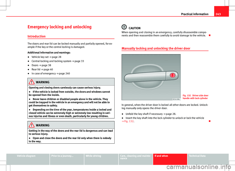
Manually locking and unlocking the driver door
Fig. 132 Driver side door
handle with lock cylinder
In general, when the driver door is locked all other doors are locked. Unlock-
ing manually only opens the driver door.
● Unfold the key shaft if necessary
⇒ page 28.
● Insert the key shaft into the lock cylinder to unlock or lock the vehicle
⇒ Fig. 132.
Vehicle diagramPrior to a journey...While drivingCare, cleaning and mainte-
nanceIf and whenTechnical Data
Page 247 of 308
245
Practical information
● Unfold the key shaft ⇒ page 28.
● Insert the key shaft into the rear lid opening ⇒ Fig. 135 and press the
release lever in the direction of the arrow to unlock the rear lid.
Vehicle diagramPrior to a journey...While drivingCare, cleaning and mainte-
nanceIf and whenTechnical Data
Page 249 of 308

247
Practical information
Components
Fig. 137 Components of
the vehicle tool kit
The set of on-board tools depends on the vehicle equipment. The following
is a description for a vehicle with all options.
The individual elements of the vehicle tools ⇒ Fig. 137
Screwdriver with hexagon socket in the handle for screwing and un-
screwing the wheel bolts once loosened. The screwdriver bit is inter-
changeable. The screwdriver may be found underneath the wheel span-
ner.
Adapter for antitheft bolt. SEAT recommend you carry the wheel bolt
adapter in the vehicle tool kit at all times. The code number of the anti-
theft wheel bolt is stamped on the front of the adapter. In case it is lost,
another adapter can be ordered using this number. Note the antitheft
bolt code for the wheels and keep it in a place other than the vehicle.
Towing eye, removable.
Wire hook for pulling off the wheel trims, integral hubcaps and the
wheel bolt caps.
1
2
34
Jack. Before storing the jack in the tool kit, fold its hook. The crank
must then be folded tight against the side of the jack in order for it to
be safely stored.
Wheel spanner.
5
6
Vehicle diagramPrior to a journey...While drivingCare, cleaning and mainte-
nanceIf and whenTechnical Data
Page 251 of 308

249
Practical information
Full hubcaps
Fig. 139 Removing the
full hubcap
Removing the full hubcap
● Take the wheel brace and the wire hook from the vehicle tool kit
⇒ page 246.
● Hook the wire through one of the grooves on the hubcap.
● Insert the wheel brace onto the wire hook
⇒ Fig. 139 and pull the hub
cap in the direction shown by the arrow.
Fitting hubcaps
Press the hubcap against the wheel so that the space for the valve fits over
the tyre valve. Make sure that the hubcap is correctly fitted all the way
around the wheel. If you are using an anti-theft wheel lock, screw it in the
opposite position to the valve. Wheel bolt capsFig. 140 Removing the
wheel bolt caps
● Take the wire hook from the vehicle tool kit ⇒ page 246.
● Insert the wire hook in the cap through the opening ⇒ Fig. 140 and pull
outwards in the direction of the arrow.
The caps protect the wheel bolts and should be remounted after changing
the tyre.
The anti-theft wheel locking bolt has a special cap. This cap only fits on an-
ti-theft locking bolts and is not for use with standard wheel bolts.
Vehicle diagramPrior to a journey...While drivingCare, cleaning and mainte-
nanceIf and whenTechnical Data
Page 253 of 308

251
Practical information
Preparations for changing a wheel
Check list
Before changing a wheel, complete the following operations in the order
given ⇒
:
1. In the event of a flat tyre, park the vehicle a safe distance from traffic and on suitable ground.
2. Apply the handbrake firmly ⇒ page 134.
3. Automatic gearbox: move the selector lever to position P
⇒ page 124.
4. Stop the engine and remove the key from the ignition ⇒ page 119.
5. Manual gearbox: Select a gear ⇒ page 124.
6. Have all vehicle occupants get out of the vehicle and wait in a safe place (for example, behind the safety barrier).
7. Chock the wheel opposite the wheel being changed with a stone or similar object.
8. If the luggage compartment is full: take the baggage out of the vehi- cle.
9. Remove the spare wheel or the temporary spare wheel and the vehi- cle tool kit from the luggage compartment.
10. Remove the wheel trims ⇒ page 248.
WARNING
Failure to follow the checklist prepared for your own safety could lead to
accidents and severe injuries.
● Always complete the operations given in the checklist and observe
the general rules of safety.
Wheel bolts
Fig. 141 Changing the
wheel: Slacken the wheel
bolts
Fig. 142 Changing the
wheel: Tyre valve
1 and
position of anti-theft
wheel locking bolt 2
Only use the tool supplied with the vehicle to loosen the wheel bolts.
Loosen the wheel bolts only about one turn before raising the vehicle with
the jack.
Vehicle diagramPrior to a journey...While drivingCare, cleaning and mainte-
nanceIf and whenTechnical Data
Page 255 of 308
253
Practical information
Raising the vehicle with the jack
Fig. 143 Jack position
points
Fig. 144 jack mounted on the left rear part of the vehi-
cle
The jack may be applied only at the jacking points shown (marks on chas-
sis) ⇒ Fig. 143. Always the relevant jacking point for the wheel to be
changed ⇒
.
Raise the vehicle using only the designated jacking points.
Vehicle diagramPrior to a journey...While drivingCare, cleaning and mainte-
nanceIf and whenTechnical Data
Page 257 of 308

255
Practical information
Changing a wheel
Fig. 145 Changing the
wheel: loosen wheel
bolts with the socket at
the end of the wheel
brace
Removing the wheel
● Please observe the check list ⇒ page 251.
● Loosen the wheel bolts ⇒ page 251.
● Jacking up the vehicle ⇒ page 253.
● Using the hexagonal socket in the wheel brace ⇒ Fig. 145, unscrew the
slackened wheel bolts and place them on a clean surface.
● Take off the wheel.
How to use the spare wheel or temporary spare wheel
Check the direction of rotation of the tyre ⇒ page 218, Tyre code.
● Place the spare wheel or temporary spare wheel into position.
● Replace the wheel bolts and tighten slightly using the hexagonal socket
on the end of the wheel brace.
● To tighten the anti-theft locking wheel bolts use the corresponding
adaptor.
● Lower the vehicle with the jack. ●
Tighten all of the wheel bolts clockwise ⇒
. Tighten the bolts in diago-
nal pairs (not in a circle).
● Put the caps, trim or full hubcap back on ⇒ page 248.
WARNING
If the wheel bolts are not treated suitably or not tightened to the correct
torque then this could lead to loss of vehicle control and to a serious ac-
cident.
● All the wheel bolts and hub threads should be clean and free of oil
and grease. The wheel bolts should be easily tightened to the correct tor-
que.
● The hexagonal socket in the wheel brace should be used for turning
wheel bolts only. Do not use it to loosen or tighten the wheel bolts.
After changing the wheel
● Clean the vehicle tools, if necessary and put them away in the luggage
compartment foam holder ⇒ page 246.
● Store the spare wheel, the temporary spare wheel or the changed wheel
securely in the luggage compartment.
● Have the tightening torque of the wheel bolts checked as soon as possi-
ble with a torque wrench ⇒ page 252.
● Have the flat tyre replaced as quickly as possible.
Vehicle diagramPrior to a journey...While drivingCare, cleaning and mainte-
nanceIf and whenTechnical Data
Page 259 of 308

257
Practical information
WARNING (Continued)
● Avoid heavy acceleration, hard braking and fast cornering.
● Drive only during 10 minutes at a maximum speed of 80 km/h
(50 mph) and subsequently check the tyre.
For the sake of the environment
Dispose of used or expired sealant observing any legal requirements.
Note
A new bottle of sealant can be purchased at SEAT dealerships.
Note
Take into account the separate instruction manual of the tire mobility set
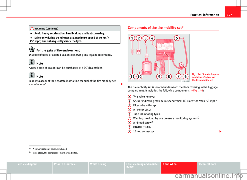
manufacturer*. Components of the tire mobility set*Fig. 146 Standard repre-
sentation: Contents of
the tire mobility set
The tire mobility set is located underneath the floor covering in the luggage
compartment. It includes the following components ⇒ Fig. 146:
Tyre valve remover
Sticker indicating maximum speed “max. 80 km/h” or “max. 50 mph”
Filler tube with cap
Air compressor
Tube for inflating tyres
Warning provided by tyre pressure monitoring system 1)
Air bleed screw 2)
ON/OFF switch
12 volt connector
1
23456789
1)
A compressor may also be included.
2) In its place, the compressor may have a button.
Vehicle diagramPrior to a journey...While drivingCare, cleaning and mainte-
nanceIf and whenTechnical Data