2012 RENAULT SCENIC setpoint
[x] Cancel search: setpointPage 16 of 510

13B-16V12 MR-372-J84-13B300$030.mif
DIESEL INJECTION
Fault finding – System operation13B
EDC16CP33
Program No.: C4
Vdiag No.: 04, 08, 18, 1C,
20, 24, 26, 28, 34, 38, 44,
4C, 54, 58, 5C, 60, 62, 74
III - Management of the damper valve
The damper valve is now responsible for two functions:
– Damping: when the engine is switched off, the flap closes in order to block the passage of air towards the cylinders.
The aim of this is to stop the engine as quickly as possible and to reduce instabilities when the engine is switched
off.
– "Valving" function depending on the engine operation: the damper valve closes by a few % to create a "venturi"
effect at the EGR valve passage section.
The aim of this is to accelerate the air flow of EGR gases and to reduce the emission of pollutants.
IV - Exhaust gas recirculation management
The EGR (Exhaust Gas Recirculation) system involves removing exhaust gases and reintroducing them into the
inlet.
This system plays a major role in reducing diesel engine emissions. The EGR system is cooled by a gas - water
exchanger, as on most Euro IV engines. This cooler has a dual position bypass valve, which allows the gas to be
cooled or not depending on the emission control requirements. The bypass circuit is inside the cooler (not visible
from the outside). The valve control rod is visible from the outside.
The exhaust gases are collected in the exhaust manifold (before the turbocharger), then directed to the EGR cooler
and the EGR valve. The EGR valve connects the air circuit between the damper valve and the inlet manifold; the
EGR valve is positioned next to the damper valve.
The EGR valve is activated every time the engine stops by performing 10opening/closing cycles. This programming
activates the EGR valve in order to prevent it from clogging. The program is no longer active if there are any system
faults.
The EGR system does not operate below 5°C (air flowmeter temperature).
– The controlled EGR cooler bypass
The EGR cooler bypass is controlled by an all-or-nothing solenoid valve, connected on one side to the vacuum
pump, and on the other side to the bypass control diaphragm. It is actuated according to the coolant temperature
and the engine operating status. Gases flow into the EGR section of the cooler unless the engine is cold, in which
case they flow through the bypass valve. There is also a regular actuation function for the bypass valve to prevent it
from clogging.
– EGR valve
The EGR valve is supplied by direct current and connected to a potentiometer copying the position of the valve.
The opening of the valve is actuated (H bridge) by a positive command 0 to 100%.
The valve is controlled using a double regulation loop.
The first loop (fastest) is a position loop. It brings the valve to the desired position by a loop connection using the
signal from the position sensor.
The second loop is slower and is an air flow loop. At a given operating point, the air flow setpoint is attained by
adjusting the quantity of exhaust gas flowing through the EGR valve and the flow of fresh air passing through the
damper valve. At a total constant flow, the more exhaust gas recirculation, the less fresh air there is and vice versa.
The air flow is measured by the flowmeter and the setpoint is attained using both the EGR valve position setpoint
and the damper valve position setpoint.
Page 263 of 510

13B-263V12 MR-372-J84-13B300$090.mif
DIESEL INJECTION
Fault finding – Status summary table13B
EDC16CP33
Program No.: C4
Vdiag No.: 04, 08, 18, 1C,
20, 24, 26, 28, 34, 38, 44,
4C, 54, 58, 5C, 60, 62, 74
*rege.: regeneration
*cool.: coolingTool status Diagnostic tool title
ET703Cruise control/speed limiter buttons
ET704Brakecontact No. 1
ET705Brakecontact No. 2
ET706Stored engine status no. 1
ET707Stored engine status no. 2
ET708Stored engine status no. 3
ET709Stored engine status no. 4
ET710Stored engine status no. 5
ET711Stored engine status no. 6
ET712Stored engine status no. 7
ET713Stored engine status no. 8
ET714Stored engine status no. 9
ET715Stored engine status no. 10
ET742Stored rege.* request status No.1
ET743Stored rege.* request status No.2
ET744Stored rege.* request status No.3
ET745Stored rege.* request status No.4
ET746Stored rege.* request status No.5
ET747Stored rege.* request status No.6
ET748Stored rege.* request status No.7
ET749Stored rege.* request status No.8
ET750Stored rege.* request status No.9
ET751Stored rege.* request status No.10
ET776Recirculated exhaust gas cool.* setpoint
ET781Heater plugs
Page 322 of 510

13B-322V12 MR-372-J84-13B300$102.mif
DIESEL INJECTION
Fault finding – Interpretation of statuses13B
COOL*: Cooling
ET776RECIRCULATED EXHAUST GAS COOL* SETPOINTS
STATUS
DEFINITION
ACTIVE: This status indicates that the recirculated exhaust gas cooling setpoint
is active.
INACTIVE: This status indicates that the recirculated exhaust gas cooling setpoint
is not active.
NOTESNone.
Conformity check: Engine stopped and ignition on and Engine running and engine coolant
temperature > 80°C
This status gives a setpoint for status ET587 Recirculated exhaust gas cooling. This programming changes
depending on the computer.
In the event of a fault, see the interpretation of faults DF209 EGR valve position sensor circuit and DF647 EGR
valve position regulation.
EDC16CP33_V18_ET776 / EDC16CP33_V1C_ET776 / EDC16CP33_V54_ET776 / EDC16CP33_V20_ET776 / EDC16CP33_V58_ET776 /
EDC16CP33_V5C_ET776 / EDC16CP33_V24_ET776 / EDC16CP33_V04_ET776 / EDC16CP33_V08_ET776 / EDC16CP33_V44_ET776 /
EDC16CP33_V4C_ET776 / EDC16CP33_V34_ET776 / EDC16CP33_V38_ET776 / EDC16CP33_V74_ET776 / EDC16CP33_V28_ET776 /
EDC16CP33_V62_ET776 / EDC16CP33_V26_ET776 / EDC16CP33_V60_ET776
EDC16CP33
Program No.: C4
VDiag No.: 04, 08, 18, 1C,
20, 24, 26, 28, 34, 38, 44,
4C, 54, 58, 5C, 60, 62, 74
AFTER REPAIRCarry out a road test, then check with the diagnostic tool.
Page 325 of 510

13B-325V12 MR-372-J84-13B300$110.mif
13B
EDC16CP33
Program No.: C4
VDiag No.: 04, 08, 18, 1C,
20, 24, 26, 28, 34, 38, 44,
4C, 54, 58, 5C, 60, 62, 74
OCR*: Opening Cyclic RatioTool parameter Diagnostic tool title
PR002Alternator charge (Mégane II ph2/Scénic II ph2 only)
PR005EGR valve opening setpoint
PR006Rail pressure regulator current
PR007Rail pressure regulator current setpoint
PR008Rail reference pressure
PR009Turbocharging pressure setpoint
PR015Engine torque
PR017Fuel flow
PR022EGR valve position feedback loop difference
PR023Air flow difference
PR030Accelerator pedal position
PR035Atmospheric pressure
PR037Refrigerant pressure (Mégane II ph2/Scénic II ph2 only)
PR038Rail pressure
PR041Turbocharging pressure
PR042Filtered turbocharging pressure
PR048OCR* rail pressure regulation valve
PR051EGR valve position feedback
PR053Engine speed requested by air conditioning
PR055Engine speed
PR059Inlet air temperature
PR061Exterior air temperature
PR063Fuel temperature
PR064Coolant temperature
PR074Battery voltage
PR077EGR valve position sensor voltage
DIESEL INJECTION
Fault finding – Parameter summary table
Page 326 of 510
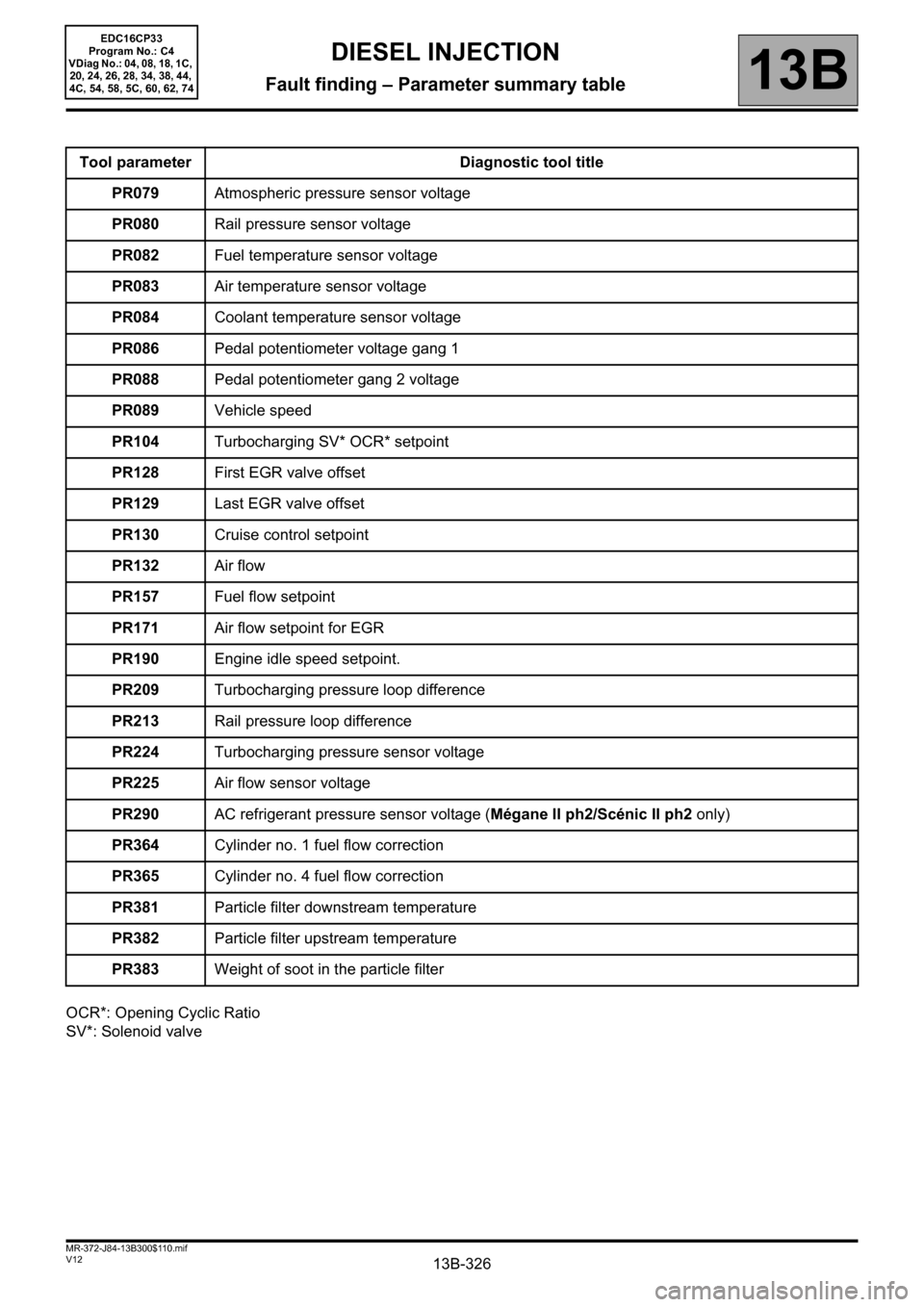
13B-326V12 MR-372-J84-13B300$110.mif
DIESEL INJECTION
Fault finding – Parameter summary table13B
EDC16CP33
Program No.: C4
VDiag No.: 04, 08, 18, 1C,
20, 24, 26, 28, 34, 38, 44,
4C, 54, 58, 5C, 60, 62, 74
OCR*: Opening Cyclic Ratio
SV*: Solenoid valveTool parameter Diagnostic tool title
PR079Atmospheric pressure sensor voltage
PR080Rail pressure sensor voltage
PR082Fuel temperature sensor voltage
PR083Air temperature sensor voltage
PR084Coolant temperature sensor voltage
PR086Pedal potentiometer voltage gang 1
PR088Pedal potentiometer gang 2 voltage
PR089Vehicle speed
PR104Turbocharging SV* OCR* setpoint
PR128First EGR valve offset
PR129Last EGR valve offset
PR130Cruise control setpoint
PR132Air flow
PR157Fuel flow setpoint
PR171Air flow setpoint for EGR
PR190Engine idle speed setpoint.
PR209Turbocharging pressure loop difference
PR213Rail pressure loop difference
PR224Turbocharging pressure sensor voltage
PR225Air flow sensor voltage
PR290AC refrigerant pressure sensor voltage (Mégane II ph2/Scénic II ph2 only)
PR364Cylinder no. 1 fuel flow correction
PR365Cylinder no. 4 fuel flow correction
PR381Particle filter downstream temperature
PR382Particle filter upstream temperature
PR383Weight of soot in the particle filter
Page 327 of 510

13B-327V12 MR-372-J84-13B300$110.mif
DIESEL INJECTION
Fault finding – Parameter summary table13B
EDC16CP33
Program No.: C4
VDiag No.: 04, 08, 18, 1C,
20, 24, 26, 28, 34, 38, 44,
4C, 54, 58, 5C, 60, 62, 74
repl*: replacement,
diff.*: differential,
OCR*: Opening Cyclic Ratio.Tool parameter Diagnostic tool title
PR385Exhaust pipe flow
PR391Mileage since particle filter repl*
PR405Cylinder no. 2 fuel flow correction
PR406Cylinder no. 3 fuel flow correction
PR412Mileage at last successful regeneration
PR414Particle filter diff* pressure
PR415Time since last regeneration
PR484Fuel regulation solenoid valve OCR*
PR490Engine air flow
PR636Turbine upstream pressure
PR667Turbine upstream temperature
PR668Turbine upstream temperature sensor voltage
PR672Damper valve position setpoint
PR739Fuel flow solenoid valve current
PR747Damper valve position
PR782Turbine upstream pressure sensor voltage
PR784DF312 recording No. 1
PR785DF312 recording No. 2
PR786DF312 recording No. 3
PR787DF312 recording No. 4
PR788DF312 recording No. 5
PR789DF312 recording No. 6
PR790DF312 recording No. 7
PR791DF312 recording No. 8
Page 328 of 510

13B-328V12 MR-372-J84-13B300$110.mif
DIESEL INJECTION
Fault finding – Parameter summary table13B
EDC16CP33
Program No.: C4
VDiag No.: 04, 08, 18, 1C,
20, 24, 26, 28, 34, 38, 44,
4C, 54, 58, 5C, 60, 62, 74
OCR*: Opening Cyclic Ratio,
SV*: Solenoid valve,
solen*: solenoid valve.Tool parameter Diagnostic tool title
PR792DF312 recording No. 9
PR793DF312 recording No. 10
PR794Stored regeneration failure no. 1
PR795Stored regeneration failure no. 2
PR796Stored regeneration failure no. 3
PR797Stored regeneration failure no. 4
PR798Stored regeneration failure no. 5
PR799Stored regeneration failure no. 6
PR800Stored regeneration failure no. 7
PR801Stored regeneration failure no. 8
PR802Stored regeneration failure no. 9
PR803Stored regeneration failure no. 10
PR808Supplier 1-0 signal
PR816Stored regeneration start No.1
PR817Stored regeneration start No. 2
PR818Stored regeneration start No.3
PR819Stored regeneration start No.4
PR820Stored regeneration start No. 5
PR821Stored regeneration start No.6
PR822Stored regeneration start No.7
PR823Stored regeneration start No.8
PR824Stored regeneration start No.9
PR825Stored regeneration start No. 10
PR846Turbocharging SV* OCR*
PR848Regeneration failure number
PR850Fuel flow solen.* current setpoint
Page 332 of 510

13B-332
AFTER REPAIRCarry out a road test, then check with the diagnostic tool.
V12 MR-372-J84-13B300$121.mif
DIESEL INJECTION
Fault finding – Interpretation of parameters13B
PR006RAIL PRESSURE REGULATOR CURRENT
PARAMETER
DEFINITIONThis parameter indicates the current absorbed by the rail pressure regulator in mA.
NOTESSpecial notes:
Only perform these tests if the parameters do not correspond with the system
operation programming.
Conformity check: Engine stopped and ignition on, or Engine running, and engine coolant
temperature > 80°C
This parameter indicates the current absorbed by the rail pressure regulator PR006 ≈ PR007 Rail pressure
regulator current setpoint.
In the event of a fault, consult the interpretation of fault DF898 Rail pressure regulator circuit.
EDC16CP33_V18_PR006 / EDC16CP33_V1C_PR006 / EDC16CP33_V54_PR006 / EDC16CP33_V20_PR006 / EDC16CP33_V58_PR006 /
EDC16CP33_V5C_PR006 / EDC16CP33_V24_PR006 / EDC16CP33_V04_PR006 / EDC16CP33_V08_PR006 / EDC16CP33_V44_PR006 /
EDC16CP33_V4C_PR006 / EDC16CP33_V34_PR006 / EDC16CP33_V38_PR006 / EDC16CP33_V74_PR006 / EDC16CP33_V28_PR006 /
EDC16CP33_V62_PR006 / EDC16CP33_V26_PR006 / EDC16CP33_V60_PR006
EDC16CP33
Program No.: C4
VDiag No.: 04, 08, 18, 1C,
20, 24, 26, 28, 34, 38, 44,
4C, 54, 58, 5C, 60, 62, 74