2012 RENAULT SCENIC charging
[x] Cancel search: chargingPage 464 of 510

13B-464V12 MR-372-J84-13B300$150.mif
DIESEL INJECTION
Fault finding – Interpretation of commands13B
MT001
CONTINUED 5
PHASE 2:
Preliminary test:
Engine speed between: 2480 rpm < X < 2520 rpm
Coolant temperature > 70°C
EGR valve feedback position < 1%
Interpretation:
If, during phase 2, no data is outside the maximum and minimum limits for each variable, interpret the Monitool
analysis for phase 3.
Note: the interpretation of faults during phase 2 should only be carried out in the following situation:
– The variables measured during phase 1 are correct, i.e. they are within the maximum and minimum authorised
limits. If this is not the case, apply the different Monitool fault finding procedures which relate to the different faults
revealed during the phase 1. To confirm the repairs or modifications carried out, run the MT001 monitool test
again.
Faults, Values outside the limitsThreshold Fault finding procedure
Air flow < Minimum thresholdMinimum threshold < Turbocharging pressure
< maximum thresholdContact Techline
Turbocharging pressure < minimum threshold Contact Techline
Turbocharging pressure > maximum
thresholdContact Techline
Air flow > maximum thresholdMinimum threshold < Turbocharging pressure
< maximum thresholdContact Techline
Turbocharging pressure < minimum threshold Contact Techline
Turbocharging pressure > maximum
thresholdFault finding procedure Monitool no. 6
Turbocharging pressure
< minimum thresholdMinimum threshold < Air flow < maximum
thresholdContact Techline
Air flow < Minimum threshold Contact Techline
Air flow > maximum threshold Contact Techline
Turbocharging pressure
> maximum thresholdMinimum threshold < Air flow < maximum
thresholdContact Techline
Air flow < Minimum threshold Contact Techline
Air flow > maximum threshold
Fault finding procedure Monitool no. 6
EDC16CP33
Program No.: C4
Vdiag No.: 04, 44
AFTER REPAIRCarry out a road test, then check with the diagnostic tool.
Page 466 of 510

13B-466V12 MR-372-J84-13B300$150.mif
DIESEL INJECTION
Fault finding – Interpretation of commands13B
MT001
CONTINUED 7
PHASE 3:
Preliminary test:
Engine speed between: 2480 rpm < X < 2520 rpm
Coolant temperature > 70°C
EGR valve feedback position < 1%
Interpretation:
If, during phase 3, there is no data outside of the maximum and minimum limits for each variable, then the air line
is correct and no component replacement is to be carried out. Check the fuel circuit or deal with present or stored
faults which are displayed on the diagnostic tool.
Note: the interpretation of faults during phase 3 should only be carried out in the following situation:
– The variables measured during phase 1 and 2 are correct, i.e. they are within the minimum and maximum
authorised limits. If this is not the case, apply the different Monitool fault finding procedures which relate to the
different faults revealed during the phase 1 and phase 2. To confirm the repairs or modifications carried out, run
the MT001 monitool test again.
Faults, Values outside the limitsThreshold Fault finding procedure
Air flow < Minimum thresholdMinimum threshold < Turbocharging
pressure < maximum thresholdFault finding procedure Monitool no. 7
Turbocharging pressure < minimum
thresholdFault finding procedure Monitool no. 8
Turbocharging pressure > maximum
thresholdContact Techline
Air flow > maximum thresholdMinimum threshold < Turbocharging
pressure < maximum thresholdContact Techline
Turbocharging pressure < minimum
thresholdContact Techline
Turbocharging pressure > maximum
thresholdContact Techline
Turbocharging pressure
< minimum thresholdMinimum threshold < Air flow < maximum
thresholdContact Techline
Air flow < Minimum thresholdFault finding procedure Monitool no. 8
Air flow > maximum threshold Contact Techline
Turbocharging pressure
> maximum thresholdMinimum threshold < Air flow < maximum
thresholdContact Techline
Air flow < Minimum threshold Contact Techline
Air flow > maximum threshold Contact Techline
EDC16CP33
Program No.: C4
Vdiag No.: 04, 44
AFTER REPAIRCarry out a road test, then check with the diagnostic tool.
Page 467 of 510

13B-467V12 MR-372-J84-13B300$150.mif
DIESEL INJECTION
Fault finding – Interpretation of commands13B
MT001
CONTINUED 8
Monitool no. 7 fault finding procedure:
– Check the fitting of the air flowmeter (direction of fitting to be observed).
– Check the tightness of the different air flowmeter clips.
– Check the + 5 V supply of connection 3KJ of component 799.
If the connection is faulty and there is a repair procedure (see Technical Note 6015A, Electrical wiring repair,
Wiring: Precautions for repair), repair the wiring, otherwise replace it.
– Check that there are no air leaks between the air flowmeter and the turbocharger.
– Run Test 5 Air flowmeter: check that there is no dust on the sensors.
If the checks do not reveal any non-conformity and the fault is still present, change the air flowmeter. Attach a
screen copy of the Monitool results.
Monitool no. 8 fault finding procedure:
– Measure the internal resistance of the turbocharger control solenoid valve by applying the interpretation of
DF054 Turbocharging solenoid valve control circuit.
–Apply Test 7 Variable geometry turbocharger control.
If the checks do not reveal any non-conformity and the fault is still present, replace the turbocharger. Attach a
screen copy of the Monitool results.
If all the checks do not allow the vehicle to be repaired, contact the Techline.
EDC16CP33
Program No.: C4
Vdiag No.: 04, 44
AFTER REPAIRCarry out a road test, then check with the diagnostic tool.
Page 472 of 510

13B-472
AFTER REPAIRCarry out a road test, then check with the diagnostic tool.
V12 MR-372-J84-13B300$170.mif
DIESEL INJECTION
Fault finding – Fault Finding Chart13B
ALP2 starting difficult or impossible
NOTESBefore analysing this customer complaint, check that there are no faults, and the
conformity (or otherwise) of the parameters and statuses, using the diagnostic tool.
If the customer complaint is not eliminated, perform the following checks.
Use the Wiring Diagram Technical Note, Laguna II ph2, Vel Satis ph2, Espace IV
ph2, Mégane II ph2, Scénic II ph2.
Is it difficult or impossible to start
the engine?PART
B
PART A:
If fault DF308 Clogged particle filter is present, consult the interpretation of DF308.
Check the engine earths.
If the engine speed is less than 200 rpm, refer to Technical Note 6014A, Charging circuit check, Starter fault
finding, Starter (formerly Technical Note 3632A).
If an engine speed of 200 rpm is achieved with starter motor in operation, PR055 Engine speed.
If the engine speed is zero with the diagnostic tool:
Measure the resistance between connections 3BG and 3BL of component 149.
If the sensor resistance is not between: 600 Ω < X < 1000 Ω, replace the sensor.
Check the continuity and absence of interference resistance on the following connections:
•3BG between the components 120 and 149,
•3BL between components 120 and 149.
Impossible
Difficult
EDC16CP33_V18_ALP02 / EDC16CP33_V1C_ALP02 / EDC16CP33_V54_ALP02 / EDC16CP33_V20_ALP02 / EDC16CP33_V58_ALP02 /
EDC16CP33_V5C_ALP02 / EDC16CP33_V24_ALP02 / EDC16CP33_V04_ALP02 / EDC16CP33_V08_ALP02 / EDC16CP33_V44_ALP02 /
EDC16CP33_V4C_ALP02 / EDC16CP33_V34_ALP02 / EDC16CP33_V38_ALP02 / EDC16CP33_V74_ALP02 / EDC16CP33_V28_ALP02 /
EDC16CP33_V62_ALP02 / EDC16CP33_V26_ALP02 / EDC16CP33_V60_ALP02
EDC16CP33
Program No.: C4
Vdiag No.: 04, 08, 18, 1C,
20, 24, 26, 28, 34, 38, 44,
4C, 54, 58, 5C, 60, 62, 74
Page 475 of 510

13B-475
AFTER REPAIRCarry out a road test, then check with the diagnostic tool.
V12 MR-372-J84-13B300$170.mif
DIESEL INJECTION
Fault finding – Fault Finding Chart13B
ALP2
CONTINUED 3
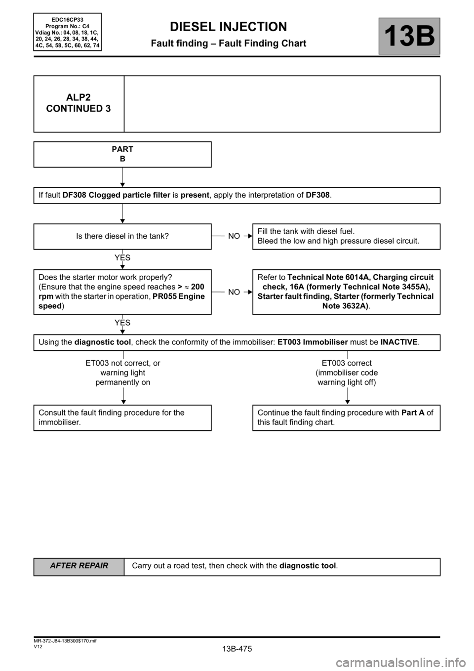
PART
B
If fault DF308 Clogged particle filter is present, apply the interpretation of DF308.
Is there diesel in the tank?Fill the tank with diesel fuel.
Bleed the low and high pressure diesel circuit.
Does the starter motor work properly?
(Ensure that the engine speed reaches > ≈ 200
rpm with the starter in operation, PR055 Engine
speed)Refer to Technical Note 6014A, Charging circuit
check, 16A (formerly Technical Note 3455A),
Starter fault finding, Starter (formerly Technical
Note 3632A).
Using the diagnostic tool, check the conformity of the immobiliser: ET003 Immobiliser must be INACTIVE.
Consult the fault finding procedure for the
immobiliser.Continue the fault finding procedure with Part A of
this fault finding chart.
NO
YES
NO
YES
ET003 not correct, or
warning light
permanently onET003 correct
(immobiliser code
warning light off)
EDC16CP33
Program No.: C4
Vdiag No.: 04, 08, 18, 1C,
20, 24, 26, 28, 34, 38, 44,
4C, 54, 58, 5C, 60, 62, 74
Page 484 of 510

13B-484
AFTER REPAIRCarry out a road test, then check with the diagnostic tool.
V12 MR-372-J84-13B300$170.mif
DIESEL INJECTION
Fault finding – Fault Finding Chart13B
ALP7 Rough idle
NOTESBefore analysing this customer complaint, check that there are no faults, and the
conformity (or otherwise) of the parameters and statuses, using the diagnostic tool.
If the customer complaint is not eliminated, perform the following checks.
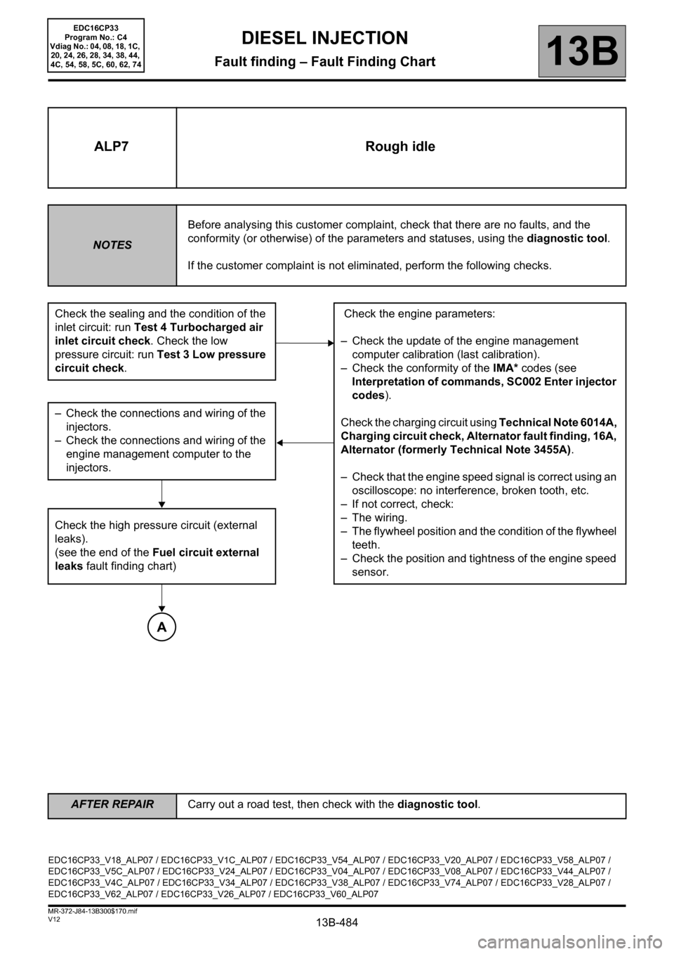
Check the sealing and the condition of the
inlet circuit: run Test 4 Turbocharged air
inlet circuit check. Check the low
pressure circuit: run Test 3 Low pressure
circuit check. Check the engine parameters:
– Check the update of the engine management
computer calibration (last calibration).
– Check the conformity of the IMA* codes (see
Interpretation of commands, SC002 Enter injector
codes).
Check the charging circuit using Technical Note 6014A,
Charging circuit check, Alternator fault finding, 16A,
Alternator (formerly Technical Note 3455A).
– Check that the engine speed signal is correct using an
oscilloscope: no interference, broken tooth, etc.
– If not correct, check:
– The wiring.
– The flywheel position and the condition of the flywheel
teeth.
– Check the position and tightness of the engine speed
sensor. – Check the connections and wiring of the
injectors.
– Check the connections and wiring of the
engine management computer to the
injectors.
Check the high pressure circuit (external
leaks).
(see the end of the Fuel circuit external
leaks fault finding chart)
A
EDC16CP33_V18_ALP07 / EDC16CP33_V1C_ALP07 / EDC16CP33_V54_ALP07 / EDC16CP33_V20_ALP07 / EDC16CP33_V58_ALP07 /
EDC16CP33_V5C_ALP07 / EDC16CP33_V24_ALP07 / EDC16CP33_V04_ALP07 / EDC16CP33_V08_ALP07 / EDC16CP33_V44_ALP07 /
EDC16CP33_V4C_ALP07 / EDC16CP33_V34_ALP07 / EDC16CP33_V38_ALP07 / EDC16CP33_V74_ALP07 / EDC16CP33_V28_ALP07 /
EDC16CP33_V62_ALP07 / EDC16CP33_V26_ALP07 / EDC16CP33_V60_ALP07
EDC16CP33
Program No.: C4
Vdiag No.: 04, 08, 18, 1C,
20, 24, 26, 28, 34, 38, 44,
4C, 54, 58, 5C, 60, 62, 74
Page 486 of 510

13B-486
AFTER REPAIRCarry out a road test, then check with the diagnostic tool.
V12 MR-372-J84-13B300$170.mif
DIESEL INJECTION
Fault finding – Fault Finding Chart13B
ALP8 Engine stalling
NOTESBefore analysing this customer complaint, check that there are no faults, and the
conformity (or otherwise) of the parameters and statuses, using the diagnostic tool.
If the customer complaint is not eliminated, perform the following checks.
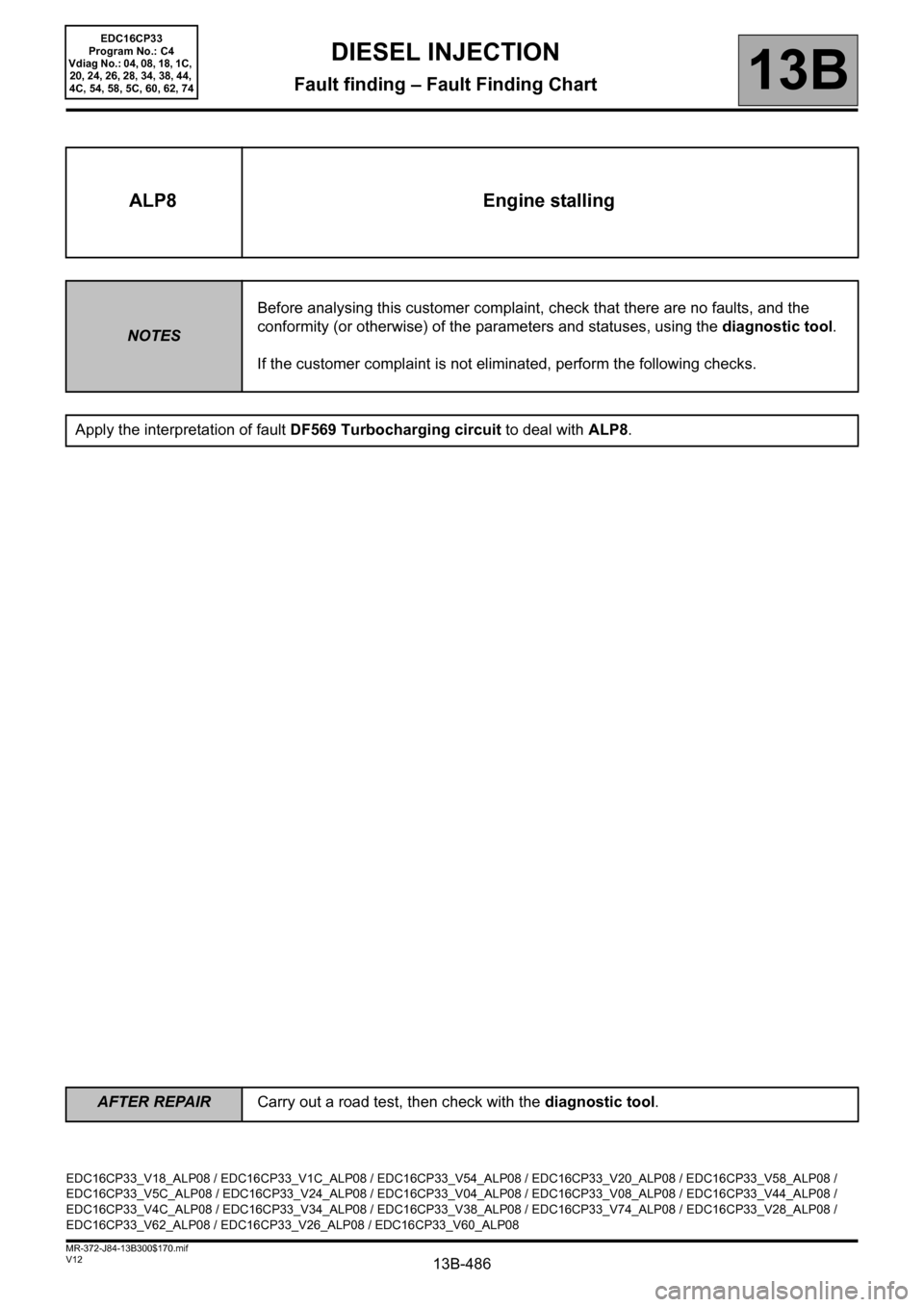
Apply the interpretation of fault DF569 Turbocharging circuit to deal with ALP8.
EDC16CP33_V18_ALP08 / EDC16CP33_V1C_ALP08 / EDC16CP33_V54_ALP08 / EDC16CP33_V20_ALP08 / EDC16CP33_V58_ALP08 /
EDC16CP33_V5C_ALP08 / EDC16CP33_V24_ALP08 / EDC16CP33_V04_ALP08 / EDC16CP33_V08_ALP08 / EDC16CP33_V44_ALP08 /
EDC16CP33_V4C_ALP08 / EDC16CP33_V34_ALP08 / EDC16CP33_V38_ALP08 / EDC16CP33_V74_ALP08 / EDC16CP33_V28_ALP08 /
EDC16CP33_V62_ALP08 / EDC16CP33_V26_ALP08 / EDC16CP33_V60_ALP08
EDC16CP33
Program No.: C4
Vdiag No.: 04, 08, 18, 1C,
20, 24, 26, 28, 34, 38, 44,
4C, 54, 58, 5C, 60, 62, 74
Page 499 of 510

13B-499V12 MR-372-J84-13B300$180.mif
DIESEL INJECTION
Fault finding – Test13B
TEST4 Turbocharged air inlet circuit check
Engine stopped: Check the sealing (leak or air intake) of the low and high pressure air circuit (before/after
turbocharger).
Check the parts that are abnormally greasy of the circuit and reveal a lack of tightness.
Check:
– the condition and fitting of the ducts (foreign, clogged, not joined, kinked, broken, pierced, cut bodies, tightness
of the mounting bolts, etc.).
– the presence, condition and fitting of the seals.
– the present and tightening of the clamps.
– The fitting of the turbocharging pressure sensor.
– The pipes and the take-off point between the air duct and the turbocharging sensor.
Carry out the necessary repairs.
Check the air filter.
Check:
– That the inlet and outlet of the air filter unit is not blocked.
– the condition and the assembly of the air filter unit (disconnected, broken, pierced …).
– The cleanliness, the conformity and the non-distortion of the filter element.
– The air flowmeter: run Test 5 Air flowmeter.
Carry out the necessary repairs
Check:
– the condition of the damper valve,
– the tightening of the mounting bolts,
– cracks in the damper valve.
Carry out the necessary repairs.
A
EDC16CP33_V18_TEST4 / EDC16CP33_V1C_TEST4 / EDC16CP33_V54_TEST4 / EDC16CP33_V20_TEST4 / EDC16CP33_V58_TEST4 /
EDC16CP33_V5C_TEST4 / EDC16CP33_V24_TEST4 / EDC16CP33_V04_TEST4 / EDC16CP33_V08_TEST4 / EDC16CP33_V44_TEST4 /
EDC16CP33_V4C_TEST4 / EDC16CP33_V34_TEST4 / EDC16CP33_V38_TEST4 / EDC16CP33_V74_TEST4 / EDC16CP33_V28_TEST4 /
EDC16CP33_V62_TEST4 / EDC16CP33_V26_TEST4 / EDC16CP33_V60_TEST4
EDC16CP33
Program No.: C4
Vdiag No.: 04, 08, 18, 1C,
20, 24, 26, 28, 34, 38, 44,
4C, 54, 58, 5C, 60, 62, 74