2012 RENAULT SCENIC light
[x] Cancel search: lightPage 425 of 510

13B-425V12 MR-372-J84-13B300$150.mif
DIESEL INJECTION
Fault finding – Interpretation of commands13B
SC002
CONTINUED
If DF066 is still present, the command has not been run correctly.
Start the procedure again and follow the instructions.
If this is still not effective, follow the procedure below:
A fault could cause DF066 to be reported, and also incorrect confirmation of command SC002.
If the power latch does not occur after switching off the ignition, the injection computer will not store the new
injector codes:
Switch off the ignition and wait for the diagnostic tool message (maximum wait 8 min): Loss of dialogue with
the computer: EDC16 CP33, check the tool connection and the computer supply.
Switch off the ignition and check that the immobiliser warning light flashes 2 seconds after the ignition is switched
off.
If the warning light flashes as soon as the ignition is switched off, the power latch has not been performed and the
command will not be taken into account.
If all these checks do not enable the command to be confirmed, contact the Techline.
EDC16CP33
Program No.: C4
Vdiag No.: 04, 08, 18, 1C,
20, 24, 26, 28, 34, 38, 44,
4C, 54, 58, 5C, 60, 62, 74
AFTER REPAIRCarry out a road test, then check with the diagnostic tool.
Page 455 of 510

13B-455V12 MR-372-J84-13B300$150.mif
DIESEL INJECTION
Fault finding – Interpretation of commands13B
AC225RAIL PRESSURE REGULATOR
NOTESPerform this fault finding procedure:
– following interpretation of an unresolved fault
– following an inconsistency recorded in the parameters,
– following a customer complaint (starting problems, engine speed instability, injection
noise).
STEP 1
Check the continuity and absence of interference resistance on the following connection:
•3RG between the components 120 and 1198.
Check the + 12 V after relay supply to the rail pressure regulator (DRV) of the following connection:
•3FB of component 1198.
If the connection or connections are faulty and there is a repair procedure (see Technical Note 6015A, Electrical
wiring repair, Wiring: Precautions for repair), repair the wiring, otherwise replace it.
Run command AC225, if you can hear a slight whistling noise and rattling from the pressure regulator, go to step
2, otherwise, check the operation of the computer output stage:
Vehicle under + after ignition feed, clear the faults displayed by the diagnostic tool.
With the voltmeter in the direct current position:
With the rail pressure regulator connected, connect the voltmeter earth lead to connection3RG of
component1198 and the positive lead to connection3FB of component1198. Run command AC225, the
voltmeter should display four successive voltages between 2 V and 2.4 V.
If the measurement is not correct, contact the Techline.
STEP 2
EDC16CP33_V18_AC225 / EDC16CP33_V1C_AC225 / EDC16CP33_V54_AC225 / EDC16CP33_V20_AC225 / EDC16CP33_V58_AC225 /
EDC16CP33_V5C_AC225 / EDC16CP33_V24_AC225 / EDC16CP33_V04_AC225 / EDC16CP33_V08_AC225 / EDC16CP33_V44_AC225 /
EDC16CP33_V4C_AC225 / EDC16CP33_V34_AC225 / EDC16CP33_V38_AC225 / EDC16CP33_V74_AC225 / EDC16CP33_V28_AC225 /
EDC16CP33_V62_AC225 / EDC16CP33_V26_AC225 / EDC16CP33_V60_AC225
EDC16CP33
Program No.: C4
Vdiag No.: 04, 08, 18, 1C,
20, 24, 26, 28, 34, 38, 44,
4C, 54, 58, 5C, 60, 62, 74
AFTER REPAIRCarry out a road test, then check with the diagnostic tool.
Page 457 of 510

13B-457V12 MR-372-J84-13B300$150.mif
DIESEL INJECTION
Fault finding – Interpretation of commands13B
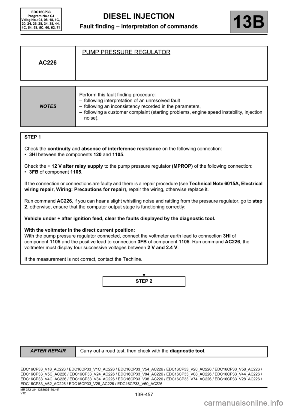
AC226PUMP PRESSURE REGULATOR
NOTESPerform this fault finding procedure:
– following interpretation of an unresolved fault
– following an inconsistency recorded in the parameters,
– following a customer complaint (starting problems, engine speed instability, injection
noise).
STEP 1
Check the continuity and absence of interference resistance on the following connection:
•3HI between the components 120 and 1105.
Check the + 12 V after relay supply to the pump pressure regulator (MPROP) of the following connection:
•3FB of component 1105.
If the connection or connections are faulty and there is a repair procedure (see Technical Note 6015A, Electrical
wiring repair, Wiring: Precautions for repair), repair the wiring, otherwise replace it.
Run command AC226, if you can hear a slight whistling noise and rattling from the pressure regulator, go to step
2, otherwise, ensure that the computer output stage is functioning correctly:
Vehicle under + after ignition feed, clear the faults displayed by the diagnostic tool.
With the voltmeter in the direct current position:
With the pump pressure regulator connected, connect the voltmeter earth lead to connection3HI of
component1105 and the positive lead to connection3FB of component1105. Run command AC226, the
voltmeter must display four successive voltages between 2 V and 2.4 V.
If the measurement is not correct, contact the Techline.
STEP 2
EDC16CP33_V18_AC226 / EDC16CP33_V1C_AC226 / EDC16CP33_V54_AC226 / EDC16CP33_V20_AC226 / EDC16CP33_V58_AC226 /
EDC16CP33_V5C_AC226 / EDC16CP33_V24_AC226 / EDC16CP33_V04_AC226 / EDC16CP33_V08_AC226 / EDC16CP33_V44_AC226 /
EDC16CP33_V4C_AC226 / EDC16CP33_V34_AC226 / EDC16CP33_V38_AC226 / EDC16CP33_V74_AC226 / EDC16CP33_V28_AC226 /
EDC16CP33_V62_AC226 / EDC16CP33_V26_AC226 / EDC16CP33_V60_AC226
EDC16CP33
Program No.: C4
Vdiag No.: 04, 08, 18, 1C,
20, 24, 26, 28, 34, 38, 44,
4C, 54, 58, 5C, 60, 62, 74
AFTER REPAIRCarry out a road test, then check with the diagnostic tool.
Page 469 of 510

13B-469
AFTER REPAIRCarry out a road test followed by a check with the diagnostic tool.
V12 MR-372-J84-13B300$160.mif
13B
EDC16CP33
Program No.: C4
Vdiag No.: 04, 08, 18, 1C,
20, 24, 26, 28, 34, 38, 44,
4C, 54, 58, 5C, 60, 62, 74
NOTESOnly refer to the customer complaints after a full check with the diagnostic tool.
NO DIALOGUE WITH ENGINE MANAGEMENT COMPUTER ALP 1
STARTING FAULT OR STARTING IMPOSSIBLE ALP 2
POOR PERFORMANCEALP 4
IRREGULAR ENGINE OPERATION ALP 5
EXTERNAL LEAKS FROM THE FUEL CIRCUIT ALP 6
ROUGH IDLEALP 7
ENGINE STALLINGALP 8
PARTICLE FILTER WARNING LIGHT COMES ON TOO FREQUENTLY ALP 9
DIESEL INJECTION
Fault finding – Customer complaints
Page 475 of 510

13B-475
AFTER REPAIRCarry out a road test, then check with the diagnostic tool.
V12 MR-372-J84-13B300$170.mif
DIESEL INJECTION
Fault finding – Fault Finding Chart13B
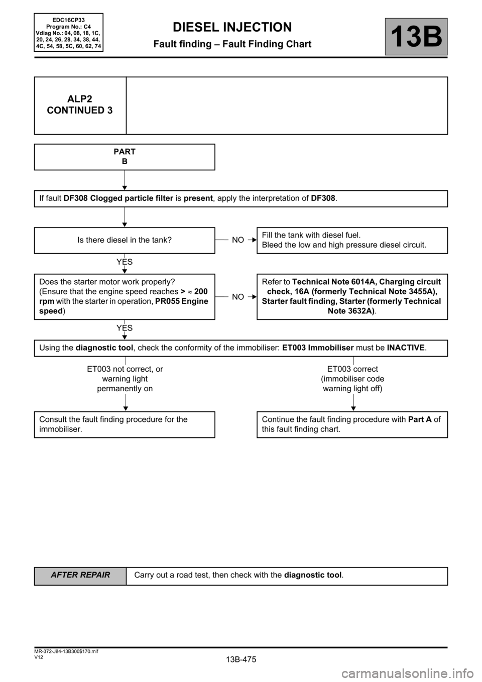
ALP2
CONTINUED 3
PART
B
If fault DF308 Clogged particle filter is present, apply the interpretation of DF308.
Is there diesel in the tank?Fill the tank with diesel fuel.
Bleed the low and high pressure diesel circuit.
Does the starter motor work properly?
(Ensure that the engine speed reaches > ≈ 200
rpm with the starter in operation, PR055 Engine
speed)Refer to Technical Note 6014A, Charging circuit
check, 16A (formerly Technical Note 3455A),
Starter fault finding, Starter (formerly Technical
Note 3632A).
Using the diagnostic tool, check the conformity of the immobiliser: ET003 Immobiliser must be INACTIVE.
Consult the fault finding procedure for the
immobiliser.Continue the fault finding procedure with Part A of
this fault finding chart.
NO
YES
NO
YES
ET003 not correct, or
warning light
permanently onET003 correct
(immobiliser code
warning light off)
EDC16CP33
Program No.: C4
Vdiag No.: 04, 08, 18, 1C,
20, 24, 26, 28, 34, 38, 44,
4C, 54, 58, 5C, 60, 62, 74
Page 476 of 510

13B-476
AFTER REPAIRCarry out a road test, then check with the diagnostic tool.
V12 MR-372-J84-13B300$170.mif
DIESEL INJECTION
Fault finding – Fault Finding Chart13B
ALP4 Poor performance
NOTESBefore analysing this customer complaint, check that there are no faults, and the
conformity (or otherwise) of the parameters and statuses, using the diagnostic tool.
If the customer complaint is not eliminated, perform the following checks.
IMPORTANT:
In the event of the engine overheating above 118°C, the computer deliberately limits the fuel flow (overheating
warning light comes on from 115°C).
– Please observe the cleanliness guidelines and safety advice.
Note:
For the M9R 724 (Vdiag 5C and 58):
The engine is limited to 3000 rpm if the vehicle is stationary or if the vehicle speed is less than 4 mph (7 km/h)
and if the engine is warm.
EDC16CP33_V18_ALP04 / EDC16CP33_V1C_ALP04 / EDC16CP33_V54_ALP04 / EDC16CP33_V20_ALP04 / EDC16CP33_V58_ALP04 /
EDC16CP33_V5C_ALP04 / EDC16CP33_V24_ALP04 / EDC16CP33_V04_ALP04 / EDC16CP33_V08_ALP04 / EDC16CP33_V44_ALP04 /
EDC16CP33_V4C_ALP04 / EDC16CP33_V34_ALP04 / EDC16CP33_V38_ALP04 / EDC16CP33_V74_ALP04 / EDC16CP33_V28_ALP04 /
EDC16CP33_V62_ALP04 / EDC16CP33_V26_ALP04 / EDC16CP33_V60_ALP04
EDC16CP33
Program No.: C4
Vdiag No.: 04, 08, 18, 1C,
20, 24, 26, 28, 34, 38, 44,
4C, 54, 58, 5C, 60, 62, 74
Page 478 of 510

13B-478
AFTER REPAIRCarry out a road test, then check with the diagnostic tool.
V12 MR-372-J84-13B300$170.mif
DIESEL INJECTION
Fault finding – Fault Finding Chart13B
ALP4
CONTINUED 2
Perform the following road test (looking for a loss of power when accelerating under full load):
– in the highest gear ratio, accelerate fully,
– lift your foot off the accelerator pedal completely for at least 2 seconds,
– accelerate fully again,
– release the accelerator pedal completely,
– accelerate slightly.
If the loss of power was not noted during slight acceleration and if there was a loss of engine power during each
acceleration at full load, replace the diesel fuel injector return rail and its overpressure valve (see MR364
(Mégane II ph2), MR370 (Scénic II ph2), MR 395 (Laguna II ph2), 402 (Vel Satis ph2), 405 (Espace IV ph2)
Mechanical, 13B, Diesel injection, Diesel injector fuel return rail: Removal - Refitting).
Check the connection and positioning of the differential pressure sensor (see MR 395 (Laguna II ph2), 402 (Vel
Satis Ph2), 405 (Espace IV ph2), 364 (Mégane II ph2), 370 (Scénic II ph2) Mechanical, 19B, Exhaust, Particle
filter pressure sensor: Removal - Refitting).
Check the conformity of the accelerator pedal position sensor, the brake pedal sensor, the atmospheric pressure
sensor, the exhaust gas recirculation valve, and the damper valve (see Interpretation of statuses and
parameters).
Check the consistency of the signal from the air flowmeter, the engine coolant temperature sensor, the fuel
temperature sensor and the engine speed sensor.
Check the connections, the continuity and the absence of interference resistance of the following components:
– the air flowmeter (apply DF056 Air flow sensor circuit)
– the engine coolant temperature sensor (apply DF001 Coolant temperature sensor circuit)
– the fuel temperature sensor (apply DF098 Fuel temperature sensor circuit)
– the engine speed sensor (apply DF195 Engine speed/camshaft sensor consistency).
A
YES
EDC16CP33
Program No.: C4
Vdiag No.: 04, 08, 18, 1C,
20, 24, 26, 28, 34, 38, 44,
4C, 54, 58, 5C, 60, 62, 74
Page 487 of 510

13B-487
AFTER REPAIRCarry out a road test, then check with the diagnostic tool.
V12 MR-372-J84-13B300$170.mif
DIESEL INJECTION
Fault finding – Fault Finding Chart13B
ALP9 PARTICLE FILTER WARNING LIGHT COMES ON TOO OFTEN
NOTESBefore dealing with this customer complaint, check that there are no faults except
DF312 Speed request, and the conformity (or otherwise) of the "parameters" and
"statuses" using the diagnostic tool. Deal with the other faults first.
If the customer complaint is not eliminated, perform the following checks.
Have the last 10 regeneration
attempts failed?Are all the regeneration failures
linked to engine cut-off?
See group parameter (ET706
Stored engine status no. 1 to
ET715 Stored engine status no.
10)
(e.g. ET706 STOPPED)Output 1 Is the distance of PR412 Distance of
last successful regeneration less
than all the parameters of group 2?
(PR794 to PR803 Stored
regeneration failure no.1 to no.10)
Is at least one status for group
1 = STATUS4?Check the exhaust pipe for leaks
or blockage. Repair if necessary.
Carry out an After-Sales
regeneration if not already
performed. To do this, see SC017
Particle filter regeneration in
Interpretation of commands.Output 2
YES
YES
NONO
YES
A
NO
B
EDC16CP33_V18_ALP09 / EDC16CP33_V1C_ALP09 / EDC16CP33_V54_ALP09 / EDC16CP33_V20_ALP09 / EDC16CP33_V58_ALP09 /
EDC16CP33_V5C_ALP09 / EDC16CP33_V24_ALP09 / EDC16CP33_V28_ALP09 / EDC16CP33_V62_ALP09 / EDC16CP33_V26_ALP09 /
EDC16CP33_V60_ALP09
EDC16CP33
Program No.: C4
Vdiag No.: 18, 1C, 20, 24,
26, 28, 54, 58, 5C, 60, 62