2012 NISSAN QASHQAI warning light
[x] Cancel search: warning lightPage 202 of 297
Downloaded from www.Manualslib.com manuals search engine The brake system has two separate hydraulic cir-
cuits. If one circuit malfunctions, you will still have
braking ability with two wheels.
BRAKE PRECAUTIONS
Vacuum assisted brake
The brake booster aids braking by using engine
vacuum. If the engine stops or the drive belt is bro-
ken, you can stop the vehicle by depressing the
brake pedal. However, greater foot pressure on the
brake pedal will be required to stop the vehicle and
the stopping distance will be longer.
Wet brakes
When the vehicle is washed or driven through wa-
ter, the brakes may get wet. As a result, your brak-
ing distance will be longer and the vehicle may pull
to one side during braking.
To dry brakes, drive the vehicle at a safe speed
while lightly pressing the brake pedal to heat up the
brakes. Do this until the brakes return to normal.
Avoid driving the vehicle at high speeds until the
brakes function correctly.
Using the brakes
Avoid resting your foot on the brake pedal while
driving. This will overheat the brakes, wear out the
brake linings and pads faster and reduce fuel
economy performance.
To help reduce brake wear and to prevent the brakes
from overheating, reduce speed and downshift to a
lower gear before going down a slope or long down-hill gradient. Overheated brakes may reduce brak-
ing performance and could result in loss of vehicle
control.
CAUTION
While driving on a slippery surface, be careful
when braking, accelerating or downshifting.
Abrupt braking actions or sudden acceleration
could cause the wheels to skid and result in an
accident.
Be aware that brakes will fade if repeated heavy
brake applications are made.
Driving uphill
When starting on a steep gradient, it is sometimes
difficult to operate the brake (AT or CVT models) or
both the brake and clutch (MT models). Use the
handbrake to hold the vehicle. Do not slip the clutch
(MT models). When ready to start, slowly release
the handbrake while depressing the accelerator
pedal and releasing the clutch (MT models) or de-
pressing the accelerator pedal (AT or CVT models).
Driving downhill
The engine braking action is effective for controlling
the vehicle while descending hills.
The gear lever (MT models) should be placed in a
gear position low enough to obtain sufficient engine
braking.
For the AT or CVT models, a low gear position in
the manual shift mode, low enough to obtain suffi-
cient engine braking, should be selected.
ANTI-LOCK BRAKING SYSTEM (ABS)
WARNING
The Anti-lock Braking System (ABS) is a so-
phisticated device, but it cannot prevent acci-
dents resulting from careless or dangerous
driving techniques. It can help maintain ve-
hicle control during braking on slippery sur-
faces. Remember that stopping distances
may also be longer on rough, gravel or snow
covered roads, or if you are using snow
chains. Always maintain a safe distance from
the vehicle in front of you. Ultimately, the
driver is responsible for safety.
Tyre type and condition may also affect brak-
ing effectiveness.
– When replacing tyres, install the specified
size of tyres on all four wheels.
– When installing a spare tyre, make sure it is the proper size and type as specified on
the tyre placard. See “Vehicle
identification” in the “9. Technical
information” section for the tyre placard
location.
– For detailed information, see “Wheels and tyres” in the “8. Maintenance and
do-it-yourself” section.
The Anti-lock Braking System (ABS) controls the
brakes so that the wheels do not lock during hard
braking or when braking on slippery surfaces. The
system detects the rotation speed at each wheel
BRAKE SYSTEM
Starting and driving5-39
Page 203 of 297

Downloaded from www.Manualslib.com manuals search engine and varies the brake fluid pressure to prevent each
wheel from locking and sliding. By preventing each
wheel from locking, the system helps the driver to
maintain steering control and helps to minimise
swerving and spinning on slippery surfaces.
Using the system
Depress the brake pedal and hold it down. Depress
the brake pedal with firm steady pressure, but do
not pump the brakes. The ABS will operate to pre-
vent the wheels from locking up. Steer the vehicle to
avoid obstacles.
WARNING
Do not pump the brake pedal. Doing so may in-
crease the stopping distance.
Self-test feature
The ABS includes electronic sensors, electric
pumps, hydraulic solenoids and a computer. The
computer has a built-in diagnostic feature that tests
the system each time you start the engine and move
thevehicleatalowspeedinforwardorreverse.
When the self-test occurs, you may hear a “clunk”
noise and/or feel a pulsation in the brake pedal. This
is normal and does not indicate a malfunction. If the
computer senses a malfunction, it switches the ABS
off and illuminates the ABS warning light on the
instrument panel. The brake system then operates
normally, but without anti-lock assistance.
If the ABS warning light illuminates during the self-
test or while driving, have the vehicle checked by a
NISSAN dealer or qualified workshop.
Normal operation
The ABS will not initiate at speeds below 5 to 10
km/h (3 to 6 MPH). The speeds will vary according
to road conditions.
When the ABS senses that one or more wheels are
close to locking up, the actuator rapidly applies and
releases hydraulic pressure. This action is similar to
pumping the brakes very quickly. You may feel a
pulsation in the brake pedal and hear a noise from
the actuator under the bonnet when it is operating.
This is normal and indicates that the ABS is working
properly. However, the pulsation may indicate that
road conditions are hazardous and extra care is re-
quired while driving. When accelerating, driving on slippery surfaces or
suddenly avoiding obstacles on roads, the vehicle
might swerve or slip. The Electronic Stability Pro-
gramme (ESP) system continuously monitors and
compares the driver’s intended speed and the travel
direction. The system adjusts wheel brake pressure
and engine torque to assist in improving vehicle sta-
bility.
When the ESP system is operating, the “SLIP”
indicator light () in the combination meter
blinks.
When only the traction control (TCS) system in
the ESP system is operating, the “SLIP” indica-
tor light (
) in the combination meter will also
blink.
If the “SLIP” indicator light () blinks, the
road conditions are slippery. Be sure to drive
carefully. See “Warning/indicator lights and au-
dible reminders” in the “2. Instruments and
controls” section.
Indicator light
If a malfunction occurs in the system, the “SLIP”
indicator light (
) and the ESP indicator light
() come on in the combination meter.
As long as these indicator lights are on, the trac-
tion control function is cancelled.
The ESP system uses Active Brake Limited Slip
(ABLS) system to improve vehicle traction. The Ac-
tive Brake Limited Slip (ABLS) system works when
one of the driving wheels is spinning on a slippery
ELECTRONIC STABILITY
PROGRAMME (ESP) SYSTEM
(where fitted)
5-40Starting and driving
Page 204 of 297
Downloaded from www.Manualslib.com manuals search engine surface. The Active Brake Limited Slip (ABLS) sys-
tem, brakes the spinning wheel to distribute the driv-
ing power to the other driving wheel.
If the vehicle is operated with the ESP system turned
off, all ESP and TCS functions will be turned off.
The Active Brake Limited Slip (ABLS) system and
ABS will still operate with the ESP system off. If the
Active Brake Limited Slip (ABLS) system or the ABS
is activated, the “SLIP” indicator light (
) will
blink and you may hear a clunk noise and/or feel a
pulsation in the brake pedal. This is normal and does
not indicate a malfunction.
While the ESP system is operating, you may feel a
pulsation in the brake pedal and hear a noise or
vibration from under the bonnet. This is normal and
indicates that the ESP system is working properly.
The ESP computer has a built in diagnostic feature
that tests the system each time the engine is started
and the vehicle moves forwards or reverses at a
slow speed. When the self-test occurs, you may
hear a clunk noise and/or feel a pulsation in the
brake pedal. This is normal and is not an indication
of a malfunction.
WARNING
The ESP system is designed to help improve
driving stability but does not prevent accidents
caused by abrupt steering operation at high
speeds, or careless or dangerous driving
techniques. Reduce vehicle speed and be es-
pecially careful when driving and cornering on
slippery surfaces. Always drive carefully.
If engine related parts, such as a muffler, are
not standard equipment or are extremely de-
teriorated, the ESP OFF indicator light (
)
and/or the “SLIP” indicator light () may
illuminate.
If brake related parts, such as brake pads,
rotors and callipers, are not standard equip-
ment or are extremely deteriorated, the ESP
system may not operate properly and the ESP
OFF indicator light (
) and/or the “SLIP”
indicator light () may illuminate.
Do not modify the vehicle’s suspension. If
suspension parts, such as shock absorbers,
struts, springs, stabiliser bars and bushings,
are not NISSAN-approved or are extremely
deteriorated, the ESP system may not oper-
ate properly. This could adversely affect ve-
hicle handling performance and the ESP OFF
indicator light (
) and/or the “SLIP” indi-
cator light () may illuminate.
When driving on extremely inclined surfaces,
such as higher banked corners, the ESP sys-
tem may not operate properly and the ESP
OFF indicator light (
) and/or the “SLIP”
indicator light () may illuminate. Do not
drive on these types of roads. If ESP OFF indi-
cator light
does illuminate after driving
on extreme surfaces, restart the engine to re-
set the ESP system.
If wheels or tyres other than the
recommended ones are used, the ESP sys-
tem may not operate properly and the ESP OFF indicator light (
) and/or the “SLIP”
indicator light () may illuminate.
The ESP system is not a substitute for winter
tyres or snow chains on a snow covered road.
NOTE
The ESP system should be switched on under
normal circumstances although it may be ad-
vantageous to switch off the ESP system to
allow wheelspin under the following condi-
tions:
– When driving in deep snow or mud.
– When trying to rock a vehicle free that is stuck in snow.
– When driving with snow chains.
If the ESP system has been switched off, drive
carefully with reduced speed. When road con-
ditions allow, ESP should be switched back
on.
Starting and driving5-41
Page 205 of 297
Downloaded from www.Manualslib.com manuals search engine ELECTRONIC STABILITY
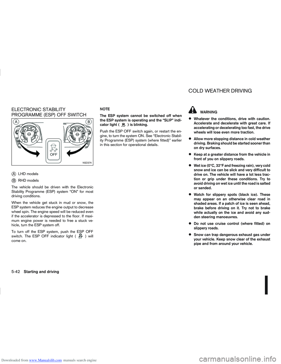
PROGRAMME (ESP) OFF SWITCH
j
ALHD models
jB RHD models
The vehicle should be driven with the Electronic
Stability Programme (ESP) system “ON” for most
driving conditions.
When the vehicle get stuck in mud or snow, the
ESP system reduces the engine output to decrease
wheel spin. The engine speed will be reduced even
if the accelerator is depressed to the floor. If maxi-
mum engine power is needed to free a stuck ve-
hicle, turn the ESP system off.
To turn off the ESP system, push the ESP OFF
switch. The ESP OFF indicator light (
) will
come on. NOTE
The ESP system cannot be switched off when
the ESP system is operating and the “SLIP” indi-
cator light (
) is blinking.
Push the ESP OFF switch again, or restart the en-
gine, to turn the system ON. See “Electronic Stabil-
ity Programme (ESP) system (where fitted)” earlier
in this section for operational details.
WARNING
Whatever the conditions, drive with caution.
Accelerate and decelerate with great care. If
accelerating or decelerating too fast, the drive
wheels will lose even more traction.
Allow more stopping distance in cold weather
driving. Braking should be started sooner than
on dry surfaces.
Keep at a greater distance from the vehicle in
front of you on slippery roads.
Wet ice (0°C, 32°F and freezing rain), very cold
snow and ice can be slick and very difficult to
drive on. The vehicle will have a lot less trac-
tion or grip under these conditions. Try to
avoid driving on wet ice until the road is salted
or sanded.
Watch for slippery spots (black ice). These
may appear on an otherwise clear road in
shaded areas. If a patch of ice is seen ahead,
brake before driving on it. Try not to brake
while actually on the ice and avoid any sud-
den steering manoeuvres.
Do not use cruise control (where fitted) on
slippery roads.
Snow can trap dangerous exhaust gas under
your vehicle. Keep snow clear of the exhaust
pipe and from around your vehicle.
NSD374
COLD WEATHER DRIVING
5-42Starting and driving
Page 217 of 297
Downloaded from www.Manualslib.com manuals search engine WARNING
Incorrect jump-starting can lead to a battery
explosion. The battery explosion may result in
severe injury or death. It may also result in
damage to the vehicle. Be sure to follow the
instructions in this section.
Explosive hydrogen gas is always present in
the vicinity of the battery. Keep all sparks and
flames away from the battery.
Always wear suitable eye protection glasses
and remove rings, bracelets, and any other
jewellery whenever working on or near a bat-
tery.
Never lean over the battery while jump-start-
ing.
Never allow battery fluid to come into contact
with eyes, skin, clothes or the vehicle’s
painted surfaces. Battery fluid is a corrosive
sulphuric acid which can cause severe burns.
If the fluid comes into contact with anything,
immediately flush the contacted area with
plenty of water.
Keep the battery out of the reach of children.
The booster battery must be rated at 12 volts.
Use of an incorrectly rated battery will dam-
age your vehicle.
Never attempt to jump-start a frozen battery.
It could explode and cause serious injury.
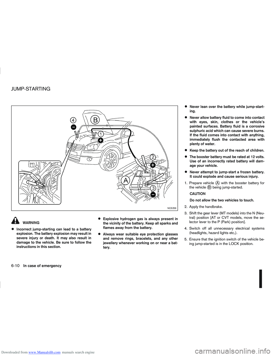
1. Prepare vehicle
jA with the booster battery for
the vehiclejB being jump-started.
CAUTION
Do not allow the two vehicles to touch.
2. Apply the handbrake.
3. Shift the gear lever (MT models) into the N (Neu- tral) position [AT or CVT models, move the se-
lector lever to the P (Park) position].
4. Switch off all unnecessary electrical systems (headlights, hazard lights etc,).
5. Ensure that the ignition switch of the vehicle be- ing jump-started is in the LOCK position.
NCE259
JUMP-STARTING
6-10In case of emergency
Page 219 of 297
Downloaded from www.Manualslib.com manuals search engine CAUTION
Three-way catalyst equipped models should
not be started by pushing the vehicle as the
three-way catalyst may be damaged.
Automatic transmission (AT) or continuously
variable transmission (CVT) models cannot be
started by pushing the vehicle. This may cause
transmission damage.
Never try to start the vehicle by towing it; when
the engine starts, the forward surge could
cause the vehicle to collide with the tow ve-
hicle.
WARNING
Never continue driving if the engine of your
vehicle overheats. Doing so could cause a ve-
hicle fire.
Never open the bonnet if steam is coming
out.
Never remove engine coolant reservoir cap
when the engine is hot. If the engine coolant
reservoir cap is removed while the engine is
hot, pressurised hot water will spurt out and
possibly cause burning, scalding or serious
injury.
If steam or coolant is coming out of the en-
gine, stand clear of the vehicle to prevent get-
ting injured.
The engine cooling fan will start whenever the
coolant temperature exceeds preset degrees.
Be careful not to allow your hands, hair, jewel-
lery or clothing to come into contact with, or
get caught in, the cooling fan or drive belts.
If the engine of your vehicle is overheating (indi-
cated by the engine coolant temperature gauge) or
if you feel a lack of engine power, detect unusual
noise, etc., proceed as follows:
1. Move and park the vehicle safely off the road and away from traffic.
2. Turn on the hazard warning flasher lights.
3. Apply the handbrake. 4. Shift the gear lever (MT models) into the N (Neu-
tral) position [AT or CVT models, move the se-
lector lever to the P (Park) position].
DO NOT STOP THE ENGINE.
5. Open all windows.
6. Switch off the air conditioner system (where fit- ted).
7. Set the heater or air conditioner temperature control to maximum “HOT” and fan speed con-
trol to maximum speed.
8. Exit the vehicle.
9. Visually inspect and listen for steam or coolant escaping from the radiator before opening the
bonnet. Wait until no steam or coolant can be
seen before proceeding.
10. Open the bonnet. For details, see “Bonnet release” in the “3. Pre-driving checks and
adjustments” section.
11. Visually check if the cooling fan is running.
12. Visually check the radiator and radiator hoses for leakage.
WARNING
If coolant is leaking, the cooling fan belt is
missing or loose or the cooling fan is not run-
ning, stop the engine.
13. After the engine cools down, check the coolant level in the engine coolant reservoir with the
engine running.
PUSH-STARTING ENGINE OVERHEAT
6-12In case of emergency
Page 235 of 297
Downloaded from www.Manualslib.com manuals search engine Handbrake*:
Confirm that your vehicle is held securely on a fairly
steep hill with only the handbrake applied.
Seats:
Check seat position controls such as seat adjust-
ers, seatback recliner, etc. to ensure they operate
smoothly and all latches lock securely in every posi-
tion. Check that the head restraints move up and
down smoothly and the locks hold securely in all
latched positions.
Seat belts:
Check that all parts of the seat belt system (e.g.
buckles, anchors, adjusters and retractors) operate
properly and smoothly, and are installed securely.
Check the belt webbing for cuts, fraying, wear or
damage. See “Seat belts” in the “1. Safety — seats,
seat belts and supplemental restraint system” sec-
tion for further details.
Steering wheel:
Check for any change in the steering conditions,
such as excessive free play, hard steering or strange
noises.
Warning lights and audible reminders:
Make sure that all warning/indicator lights and au-
dible reminders are operating properly.
Windscreen defogger:
Check that the air comes out of the defogger outlets
properly when operating the heater or air condi-
tioner.Windscreen wiper and washer*:
Check that the wipers and washer operate properly
and that the wipers do not streak.
When performing any inspection or maintenance
work on your vehicle, always take care to prevent
serious accidental injury to yourself or damage to
the vehicle. The following are general precautions
which should be closely observed.
Park the vehicle on a level surface, apply the
handbrake securely and block the wheels to
prevent the vehicle from moving. For a manual
transmission models, move the gear lever to
N (Neutral) position.[For automatic transmis-
sion or continuously variable transmission
models: move the selector lever to P (Park)
position.]
Do not work under the engine bonnet while
the engine is hot. Turn off the engine and wait
until it cools down.
Be sure to turn the ignition switch to the “OFF”
or LOCK position.
When the ignition switch is in the ON or Acc
position, the cooling fan may start to operate
suddenly even when the engine is not run-
ning. To avoid injury, always disconnect the
negative battery cable before working near
the engine.
If you must work with the engine running,
keep your hands, clothing, hair and tools away
from moving fans, belts and any other moving
parts.
It is advisable to remove ties and any jewel-
lery, such as rings, watches, etc. before work-
ing on your vehicle.
MAINTENANCE PRECAUTIONS
8-4Maintenance and do-it-yourself
Page 242 of 297

Downloaded from www.Manualslib.com manuals search engine CHANGING ENGINE OIL FILTER
WARNING
NISSAN recommends contacting a NISSAN
dealer or qualified workshop for engine oil fil-
ter servicing.
NISSAN GREEN PROGRAM
A used oil filter should be disposed of at a
rubbish tip having proper facilities.
HR16DE, MR20DE or K9K engine
Removal:
1. Drain the engine oil. For details, see “Changing engine oil” earlier in this section.
2. Loosen the engine oil filter unit with an oil filter wrench. Depending on the engine model, a spe-
cial cap type wrench may be required. See a
NISSAN dealer or qualified workshop, if in doubt. 3. Remove the engine oil filter unit.
4. Wipe the engine oil filter mounting surface with a
clean rag.
CAUTION
If any oil is spilled on the engine or the ve-
hicle, thoroughly wipe it clean.
Installation:
1. Clean and re-install the drain plug along with a new washer. For tightening torque details, see
“Changing engine oil” earlier in this section.
2. Coat the rubber gasket on the new engine oil fil- ter unit with clean engine oil.
3. Install the engine oil filter unit by hand until a slight resistance is felt, then tighten additionally
2/3ofaturn.Engine oil filter tightening torques:
HR16DE, MR20DE engine:
17.7 (1.8 kg-m, 13 ft-lb)
K9K engine:
14 (1.4 kg-m, 10 ft-lb)
4. Add engine oil and check the oil level with the engine oil dipstick. For details, see “Checking
engine oil level” earlier in this section and “Ca-
pacities and recommended fuel/lubricants” in the
“9. Technical information” section.
5. Install the engine oil filler cap.
6. Start the engine.
NDI656Z
HR16DE or MR20DE engine
NDI985Z
K9K engine
Maintenance and do-it-yourself8-11