2012 NISSAN QASHQAI pressure
[x] Cancel search: pressurePage 199 of 297

Downloaded from www.Manualslib.com manuals search engine steep slope consider the incline (the towing
weights quoted are for a 12% slope).
Follow the trailer manufacturer’s instructions.
Have your vehicle serviced more often than at
the intervals specified in the separately provided
Warranty Information and Maintenance booklet.
Trailer towing requires more fuel than under nor-
mal circumstances because of a considerable
increase in traction power required and resis-
tance.
When towing a trailer, observe the following re-
stricted towing speed:
Speed: below 100 km/h (62 MPH)
CAUTION
While towing a trailer, check the engine coolant
temperature gauge regularly to prevent engine
overheating.
TYRE PRESSURE
When towing a trailer, inflate the vehicle tyres to the
maximum recommended COLD tyre pressure, as
indicated on the tyre placard (for full loading). Make
sure the trailer tyre pressures are correct.
CAUTION
Do not tow a trailer when the vehicle is installed
with a temporary-use spare tyre.
SAFETY CHAINS
Always use a suitable chain between the vehicle
and trailer. The chain should be attached to the hitch
and not to the vehicle bumper or axle. Be sure to
leave enough slack in the chain to permit turning
corners. The chain should not drag on the ground:
passing the chain across the trailer hitch may be the
best practice depending on your trailer.
TRAILER BRAKES
Ensure that trailer brakes are installed as required
by local regulations. Also check that all other trailer
equipment conforms to local regulations.
TRAILER DETECTION (where fitted)
When towing a trailer and the turn signal switch is
used, the electrical system of the vehicle will detect
an additional electrical load of the trailer lighting. As
a result, the trailer direction indicator light comes
on.
INSTALLATION OF COUPLING
DEVICE
NISSAN recommends that the coupling device for
trailer towing be installed under the following condi-
tions:
Maximum permissible vertical load on the cou-
pling device: 736 N (75 kg, 165 lb)
The coupling device, mounting points and instal-
lation parts on your vehicle: as shown as an ex-
ample in the illustration. Follow all of the coupling device manufacturer’s in-
structions for installation and use.
5-36Starting and driving
Page 201 of 297
Downloaded from www.Manualslib.com manuals search engine When leaving your vehicle unoccupied:
Always remove the ignition key or Intelligent Key
(where fitted) and take it with you – even in your
own garage.
Close all windows completely and lock all doors.
Always park your vehicle where it can be seen.
At night, park in a well lit area.
If the vehicle is equipped with an alarm or immo-
bilization device, use it – even for short periods.
Do not leave children and pets in the vehicle
unattended.
Do not leave valuables on view to tempt a thief.
Always take your valuables with you. If you must
leave something in your vehicle, lock it in the lug-
gage compartment or hide it out of sight.
Do not leave the vehicle documents in your ve-
hicle. In the unfortunate event of your vehicle
being stolen, the documents will only help a thief
to sell the vehicle.
Do not leave articles on a roof rack as they are
particularly vulnerable. If possible, remove them
from the rack and lock them inside the vehicle.
Do not leave the spare key or Intelligent Key in
the vehicle – keep it in a safe place at home.
Do not leave a note of your vehicle’s key number
in the vehicle. A thief may break into the vehicle,
note the key number and return with a new key
and drive the vehicle.
WARNING
If the Electrically Power Assisted Steering
warning light (EPAS) illuminates while driv-
ing, the power assist for steering will be dis-
abled. Greater steering efforts are required to
operate the steering wheel, especially in
sharp turns and at low speed. Stop the ve-
hicle as soon as safely possible and contact a
NISSAN dealer or qualified workshop for fur-
ther assistance.
In certain circumstances, factors external to
the EPAS system may contribute to the illumi-
nation of the warning light. If the warning light
illuminates, stop the vehicle as soon as safely
possible if driving. Turn the ignition switch to
the “OFF” position and wait for approximately
20 seconds, then turn the ignition switch to
the ON position again. If the light remains illu-
minated, we recommend you to contact a
NISSAN dealer or qualified workshop. See
“Warning/indicator lights and audible
reminders” in the “2. Instruments and
controls” section for further details regarding
the EPAS warning light.
The EPAS (Electrically Power Assisted Steering)
system is designed to assist steering.
The steering may appear to feel slightly stiff follow-
ing parking manoeuvres including a great deal of
steering. This is not a malfunction; it is caused by a
control system designed to prevent the motor from overheating. No servicing is required. The EPAS
system will return to normal operation the next time
the vehicle is driven.
Similarly, the EPAS system may not provide full as-
sistance during periods of reduced battery voltage
but will recover once normal battery voltage is re-
stored.
If the EPAS warning light comes on while the engine
is running, it may indicate that the EPAS system is
not working properly. As result greater steering ef-
forts are required to steer the steering wheel, espe-
cially in sharp turns and at low speeds. Have the
system checked by a NISSAN dealer or qualified
workshop as soon as possible.
NOTE
Incorrectly inflated tyres can lead to poor steer-
ing ability and make the driver suspect a steering
problem: keep the vehicle’s tyres inflated to the
correct pressure at all times.
CAUTION
Any malfunction or accident that could have dam-
aged the steering components (including actual
or attempted theft damage) should be reported
to a NISSAN dealer or qualified workshop.
VEHICLE SECURITY
POWER STEERING SYSTEM
5-38Starting and driving
Page 202 of 297
Downloaded from www.Manualslib.com manuals search engine The brake system has two separate hydraulic cir-
cuits. If one circuit malfunctions, you will still have
braking ability with two wheels.
BRAKE PRECAUTIONS
Vacuum assisted brake
The brake booster aids braking by using engine
vacuum. If the engine stops or the drive belt is bro-
ken, you can stop the vehicle by depressing the
brake pedal. However, greater foot pressure on the
brake pedal will be required to stop the vehicle and
the stopping distance will be longer.
Wet brakes
When the vehicle is washed or driven through wa-
ter, the brakes may get wet. As a result, your brak-
ing distance will be longer and the vehicle may pull
to one side during braking.
To dry brakes, drive the vehicle at a safe speed
while lightly pressing the brake pedal to heat up the
brakes. Do this until the brakes return to normal.
Avoid driving the vehicle at high speeds until the
brakes function correctly.
Using the brakes
Avoid resting your foot on the brake pedal while
driving. This will overheat the brakes, wear out the
brake linings and pads faster and reduce fuel
economy performance.
To help reduce brake wear and to prevent the brakes
from overheating, reduce speed and downshift to a
lower gear before going down a slope or long down-hill gradient. Overheated brakes may reduce brak-
ing performance and could result in loss of vehicle
control.
CAUTION
While driving on a slippery surface, be careful
when braking, accelerating or downshifting.
Abrupt braking actions or sudden acceleration
could cause the wheels to skid and result in an
accident.
Be aware that brakes will fade if repeated heavy
brake applications are made.
Driving uphill
When starting on a steep gradient, it is sometimes
difficult to operate the brake (AT or CVT models) or
both the brake and clutch (MT models). Use the
handbrake to hold the vehicle. Do not slip the clutch
(MT models). When ready to start, slowly release
the handbrake while depressing the accelerator
pedal and releasing the clutch (MT models) or de-
pressing the accelerator pedal (AT or CVT models).
Driving downhill
The engine braking action is effective for controlling
the vehicle while descending hills.
The gear lever (MT models) should be placed in a
gear position low enough to obtain sufficient engine
braking.
For the AT or CVT models, a low gear position in
the manual shift mode, low enough to obtain suffi-
cient engine braking, should be selected.
ANTI-LOCK BRAKING SYSTEM (ABS)
WARNING
The Anti-lock Braking System (ABS) is a so-
phisticated device, but it cannot prevent acci-
dents resulting from careless or dangerous
driving techniques. It can help maintain ve-
hicle control during braking on slippery sur-
faces. Remember that stopping distances
may also be longer on rough, gravel or snow
covered roads, or if you are using snow
chains. Always maintain a safe distance from
the vehicle in front of you. Ultimately, the
driver is responsible for safety.
Tyre type and condition may also affect brak-
ing effectiveness.
– When replacing tyres, install the specified
size of tyres on all four wheels.
– When installing a spare tyre, make sure it is the proper size and type as specified on
the tyre placard. See “Vehicle
identification” in the “9. Technical
information” section for the tyre placard
location.
– For detailed information, see “Wheels and tyres” in the “8. Maintenance and
do-it-yourself” section.
The Anti-lock Braking System (ABS) controls the
brakes so that the wheels do not lock during hard
braking or when braking on slippery surfaces. The
system detects the rotation speed at each wheel
BRAKE SYSTEM
Starting and driving5-39
Page 203 of 297

Downloaded from www.Manualslib.com manuals search engine and varies the brake fluid pressure to prevent each
wheel from locking and sliding. By preventing each
wheel from locking, the system helps the driver to
maintain steering control and helps to minimise
swerving and spinning on slippery surfaces.
Using the system
Depress the brake pedal and hold it down. Depress
the brake pedal with firm steady pressure, but do
not pump the brakes. The ABS will operate to pre-
vent the wheels from locking up. Steer the vehicle to
avoid obstacles.
WARNING
Do not pump the brake pedal. Doing so may in-
crease the stopping distance.
Self-test feature
The ABS includes electronic sensors, electric
pumps, hydraulic solenoids and a computer. The
computer has a built-in diagnostic feature that tests
the system each time you start the engine and move
thevehicleatalowspeedinforwardorreverse.
When the self-test occurs, you may hear a “clunk”
noise and/or feel a pulsation in the brake pedal. This
is normal and does not indicate a malfunction. If the
computer senses a malfunction, it switches the ABS
off and illuminates the ABS warning light on the
instrument panel. The brake system then operates
normally, but without anti-lock assistance.
If the ABS warning light illuminates during the self-
test or while driving, have the vehicle checked by a
NISSAN dealer or qualified workshop.
Normal operation
The ABS will not initiate at speeds below 5 to 10
km/h (3 to 6 MPH). The speeds will vary according
to road conditions.
When the ABS senses that one or more wheels are
close to locking up, the actuator rapidly applies and
releases hydraulic pressure. This action is similar to
pumping the brakes very quickly. You may feel a
pulsation in the brake pedal and hear a noise from
the actuator under the bonnet when it is operating.
This is normal and indicates that the ABS is working
properly. However, the pulsation may indicate that
road conditions are hazardous and extra care is re-
quired while driving. When accelerating, driving on slippery surfaces or
suddenly avoiding obstacles on roads, the vehicle
might swerve or slip. The Electronic Stability Pro-
gramme (ESP) system continuously monitors and
compares the driver’s intended speed and the travel
direction. The system adjusts wheel brake pressure
and engine torque to assist in improving vehicle sta-
bility.
When the ESP system is operating, the “SLIP”
indicator light () in the combination meter
blinks.
When only the traction control (TCS) system in
the ESP system is operating, the “SLIP” indica-
tor light (
) in the combination meter will also
blink.
If the “SLIP” indicator light () blinks, the
road conditions are slippery. Be sure to drive
carefully. See “Warning/indicator lights and au-
dible reminders” in the “2. Instruments and
controls” section.
Indicator light
If a malfunction occurs in the system, the “SLIP”
indicator light (
) and the ESP indicator light
() come on in the combination meter.
As long as these indicator lights are on, the trac-
tion control function is cancelled.
The ESP system uses Active Brake Limited Slip
(ABLS) system to improve vehicle traction. The Ac-
tive Brake Limited Slip (ABLS) system works when
one of the driving wheels is spinning on a slippery
ELECTRONIC STABILITY
PROGRAMME (ESP) SYSTEM
(where fitted)
5-40Starting and driving
Page 209 of 297
Downloaded from www.Manualslib.com manuals search engine TEMPORARY-USE SPARE TYRE
The temporary-use spare tyre is designed for emer-
gency use only. This spare tyre should be used
ONLY for very short periods and NEVER be used
for long drives or extended periods.
Observe the following precautions if the temporary-
use spare tyre must be used, otherwise your vehicle
could be damaged or involved in an accident.
WARNING
Any continuous road use of this tyre could result
in tyre failure, loss of vehicle control, and pos-
sible personal injury.
CAUTION
The temporary-use spare tyre should be used
only in emergencies. It should be replaced by
the standard tyre at the first opportunity.
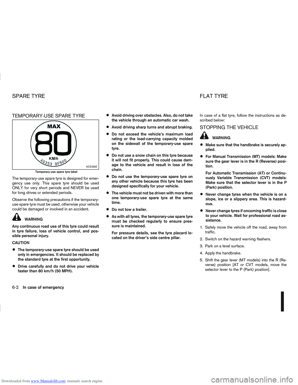
Drive carefully and do not drive your vehicle
faster than 80 km/h (50 MPH).
Avoid driving over obstacles. Also, do not take
the vehicle through an automatic car wash.
Avoid driving sharp turns and abrupt braking.
Do not exceed the vehicle’s maximum load
rating or the load-carrying capacity molded
on the sidewall of the temporary-use spare
tyre.
Do not use a snow chain on this tyre because
it will not fit properly. This could cause dam-
age to the vehicle and result in loss of the
chain.
Do not use the temporary-use spare tyre on
any other vehicle because this tyre has been
designed specifically for your vehicle.
The vehicle must not be driven with more than
one temporary-use spare tyre at the same
time.
Do not tow a trailer.
As with all tyres, the temporary-use spare tyre
must be checked regularly to ensure pres-
sure is maintained.
For pressure details, see the tyre placard lo-
cated on the driver’s side centre pillar. In case of a flat tyre, follow the instructions as de-
scribed below:
STOPPING THE VEHICLE
WARNING
Make sure that the handbrake is securely ap-
plied.
For Manual Transmission (MT) models: Make
sure the gear lever is in the R (Reverse) posi-
tion.
For Automatic Transmission (AT) or Continu-
ously Variable Transmission (CVT) models:
Make sure that the selector lever is in the P
(Park) position.
Never change tyres when the vehicle is on a
slope, ice or a slippery area. This is hazard-
ous.
Never change tyres if oncoming traffic is close
to your vehicle. Wait for professional road as-
sistance.
1. Safely move the vehicle off the road, away from traffic.
2. Switch on the hazard warning flashers.
3. Park on a level surface.
4. Apply the handbrake.
5. Shift the gear lever (MT models) into the R (Re- verse) position [AT or CVT models, move the
selector lever to the P (Park) position].
NCE069Z
Temporary-use spare tyre label
SPARE TYRE FLAT TYRE
6-2In case of emergency
Page 213 of 297
Downloaded from www.Manualslib.com manuals search engine CAUTION
The wheel is heavy. Be sure that your feet are
clear of the wheel and use gloves as necessary
to avoid injury.
Installing the wheel
WARNING
The temporary use spare tyre is designed for
emergency use. See “Spare tyre” earlier in
this section.
Never use wheel nuts other than those pro-
vided with your vehicle. Incorrect wheel nuts
or improperly tightened wheel nuts may cause
the wheel to become loose or come off. This
could cause an accident.
Never use oil or grease on the wheel studs or
nuts. This may cause the wheel nuts to be-
come loose.
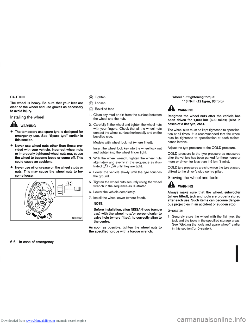
jATighten
jB Loosen
jC Bevelled face
1. Clean any mud or dirt from the surface between the wheel and the hub.
2. Carefully fit the wheel and tighten the wheel nuts with your fingers. Check that all the wheel nuts
contact the wheel surface horizontally and on the
bevelled side.
Models with wheel lock nut (where fitted):
Insert the wheel lock key into the wheel lock nut
and tighten into the wheel finger tight.
3. With the wheel wrench, tighten the wheel nuts alternately and evenly in the sequence as illus-
trated (
j1-j5 ) until they are tight.
4. Lower the vehicle slowly until the tyre touches the ground.
5. Tighten the wheel nuts securely using the wheel wrench in the sequence as illustrated.
6. Lower the vehicle completely.
7. Install the wheel cover (where fitted). NOTE
Before installation, align NISSAN logo (centre
cap) with the wheel nuts/or perpendicular to
valve hole (where fitted), to correctly align to
the centre.
As soon as possible, tighten the wheel nuts to
the specified torque with a torque wrench. Wheel nut tightening torque:
113 (12 kg-m, 83 ft-lb)
WARNING
Retighten the wheel nuts after the vehicle has
been driven for 1,000 km (600 miles) (also in
cases of a flat tyre, etc.).
The wheel nuts must be kept tightened to specifica-
tion at all times. It is recommended that the wheel
nuts be tightened to specification at each mainte-
nance interval.
Adjust the tyre pressure to the COLD pressure.
COLD pressure is the tyre pressure as measured
after the vehicle has been parked for three hours or
more or driven for less than 1.6 km (1 mile).
COLD tyre pressures are shown on the tyre placard
affixed to the driver’s side centre pillar.
Stowing the wheel and tools
WARNING
Always make sure that the wheel, subwoofer
(where fitted), jack and tools are properly stored
after each use. Such items can become danger-
ous projectiles in an accident or sudden stop.
5–seater
1. Securely store the wheel with the flat tyre, the jack and the tools in the specified storage areas.
See “Getting the tools and spare wheel” earlier
in this section(for 5–seater).NCE287Z
6-6In case of emergency
Page 216 of 297
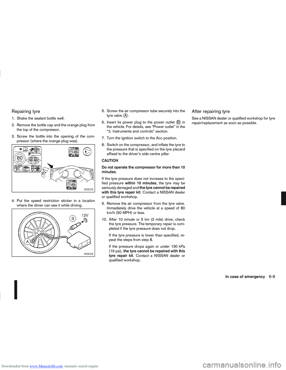
Downloaded from www.Manualslib.com manuals search engine Repairing tyre
1. Shake the sealant bottle well.
2. Remove the bottle cap and the orange plug fromthe top of the compressor.
3. Screw the bottle into the opening of the com- pressor (where the orange plug was).
4. Put the speed restriction sticker in a location where the driver can see it while driving. 5. Screw the air compressor tube securely into the
tyre valvejA.
6. Insert its power plug to the power outlet
jBin
the vehicle. For details, see “Power outlet” in the
“2. Instruments and controls” section.
7. Turn the ignition switch to the Acc position.
8. Switch on the compressor, and inflate the tyre to the pressure that is specified on the tyre placard
affixed to the driver’s side centre pillar.
CAUTION
Do not operate the compressor for more than 10
minutes.
If the tyre pressure does not increase to the speci-
fied pressure within 10 minutes , the tyre may be
seriously damaged and the tyre cannot be repaired
with this tyre repair kit . Contact a NISSAN dealer
or qualified workshop.
9. Remove the air compressor from the tyre valve. Immediately drive the vehicle at a speed of 80
km/h (50 MPH) or less.
10. After 10 minute or 5 km (3 mile) drive, check the tyre pressure. The temporary repair is com-
pleted if the tyre pressure does not drop.
If the tyre pressure is lower than specified, re-
peat the steps from step 5.
If the pressure drops again or under 130 kPa
(19 psi), the tyre cannot be repaired with this
tyre repair kit. Contact a NISSAN dealer or
qualified workshop.
After repairing tyre
See a NISSAN dealer or qualified workshop for tyre
repair/replacement as soon as possible.
NCE315
NCE316
In case of emergency6-9
Page 225 of 297
Downloaded from www.Manualslib.com manuals search engine In order to maintain the appearance of your vehicle,
it is important to take proper care of it.
Whenever possible, park your vehicle inside a ga-
rage or in a covered area to minimise the chances
of damaging the paint surface of your vehicle.
When it is necessary to park outside, park in a shady
area or protect the vehicle with a body cover.Be
careful not to scratch the paint surface when put-
ting on or removing the body cover.
WASHING
In the following instances, wash your vehicle as soon
as possible to protect the paint surface:
After a rainfall, to prevent possible damage from
acid rain.
After driving on coastal roads.
When contaminants such as soot, bird drop-
pings, tree sap, metal particles or insects get on
the paint surface.
When dust or mud builds up on the paint sur-
face.
1. Wash the vehicle surface with a wet sponge and plenty of water.
2. Clean the vehicle surface gently and thoroughly using a mild soap or a special vehicle wash sham-
poo mixed with clean, lukewarm (never hot) wa-
ter. CAUTION
Do not wash the vehicle with strong house-
hold soap, strong chemical detergents, petrol
or solvents.
Do not wash the vehicle in direct sunlight or
while the vehicle body is hot, as the paint sur-
face may become water-spotted.
Avoid using tight-napped or rough cloths,
such as washing mitts. Care must be taken
when removing caked-on dirt or other foreign
substances so the paint surface is not
scratched or damaged.
3. Rinse the vehicle thoroughly with plenty of clean water.
4. Use a damp chamois to dry the paint surface to avoid leaving water spots.
When washing the vehicle, take care of the follow-
ing:
Inside flanges, joints and folds on the doors, back
door and bonnet are particularly vulnerable to
the effects of road salt. Therefore, these areas
must be cleaned regularly.
Be sure that the drain holes in the lower edge of
the doors are not clogged.
Spray water to the underbody and in the wheel
wells to loosen the dirt and/or wash away road
salt.
If using a high pressure washer always follow
the recommendations on the equipment (pres-
sure and spraying distance).
CAUTION
Do not spray directly into the engine compart-
ment with a high-pressure washer/hose this
could damage the engine.
If there are damaged areas on the vehicle (e.g.
painted bumpers or headlamp assembly), it is
not recommended to direct the high pressure jet
on to them. Carefully wash these areas by hand.
Avoid the entry of water into the locks.
REMOVING SPOTS
Remove tar and oil spots, industrial dust, insects,
and tree sap as quickly as possible from the paint
surface to avoid lasting damage or staining. Special
cleaning products are available at a NISSAN dealer
or any automotive accessory store.
WAXING
Regular waxing protects the paint surface and helps
to retain a new vehicle appearance.
After waxing, polishing is recommended to remove
built-up residue.
A NISSAN dealer or qualified workshop can assist
you in choosing the appropriate waxing products.
CAUTION
Wash your vehicle thoroughly and completely
before applying wax to the paint surface.
CLEANING EXTERIOR
7-2Appearance and care