2012 NISSAN NOTE driving
[x] Cancel search: drivingPage 2 of 235

Foreword
Welcome to the growing family of new NISSAN owners. This vehicle has been delivered to you with confidence. It has been produced using the latest techniques
and strict quality control.
This manual was prepared to help you understand the operation and maintenance of your vehicle so that you may enjoy many kilometres (miles) of driving pleasure.
Please read through this manual before operating your vehicle.
A separate Warranty Information & Maintenance Booklet explains in detail the warranty coverage that applies to your vehicle.
Your NISSAN dealer knows your vehicle best. When you require any service or have any questions, your NISSAN dealer will be glad to assist you with the extensive
resources available for you.
IMPORTANT SAFETY INFORMATION
REMINDERS FOR SAFETY!
Follow these important driving rules to help ensure a safe and complete trip for
you and your passengers!
•NEVER drive under the influence of alcohol or drugs.
•ALWAYS observe posted speed limits and never drive too fast for condi-
tions.
•ALWAYS use your seat belts and appropriate child restraint systems.
Preteen children should be seated in the rear seat.
•ALWAYS provide information about the proper use of vehicle safety fea-
tures to all occupants of the vehicle.
•ALWAYS review this Owner’s Manual for important safety information.
WHEN READING THE MANUAL
This manual includes information for all options available on this model. There-
fore, you may find some information that does not apply to your vehicle.
All information, specifications and illustrations in this manual are those in effect
at the time of printing. NISSAN reserves the right to change specifications or
designs at any time without notice and without obligation.
MODIFICATION OF YOUR VEHICLE
This vehicle should not be modified. Modifications could affect its performance,
safety or durability, and may even violate governmental regulations. In addition,
damage or performance problems resulting from modifications may not be cov-
ered under NISSAN warranties.
READ FIRST — THEN DRIVE SAFELY
Before driving your vehicle, read this Owner’s Manual carefully. This will ensure
familiarity with controls and maintenance requirements, assisting you in the safe
operation of your vehicle.
Throughout this manual the following symbols and words are used:
WARNING
Indicates the presence of a hazard that could cause death or serious per-
sonal injury. To avoid or reduce the risk, the procedures described must be
followed precisely.
CAUTION
Indicates the presence of a hazard that could cause minor or moderate per-
sonal injury, or damage to your vehicle. To avoid or reduce the risk, the pro-
cedures described must be followed carefully.
NOTE
Indicates additional helpful information.
Page 5 of 235

ContentsIllustrated table of contents0
Safety — seats, seat belts and supplemental
restraint system1
Instruments and controls2
Pre-driving checks and adjustments3
Heater and air conditioner, and audio system4
Starting and driving5
In case of emergency6
Appearance and care7
Maintenance and do-it-yourself8
Technical information9
Index10
Page 20 of 235

FRONT SEATS
Manual seat adjustment
WARNING
•Do not adjust the driver’s seat while driving.
The seat may move suddenly and could cause
loss of control of the vehicle.
•After adjustment, gently rock in the seat to
make sure it is securely locked.
•The seatback should not be reclined any more
than needed for comfort. Seat belts are most
effective when the passenger sits well back
and upright in the seat. If the seatback is re-
clined, the risk of sliding under the lap belt
and being injured is increased.
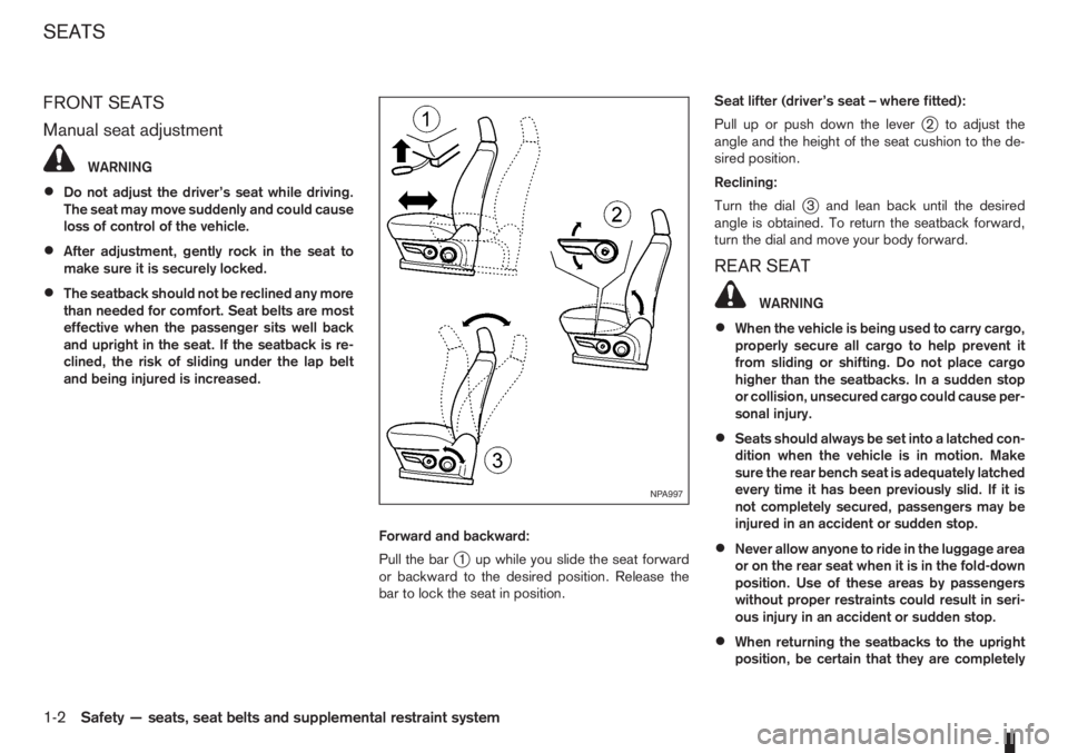
Forward and backward:
Pull the bar
j1 up while you slide the seat forward
or backward to the desired position. Release the
bar to lock the seat in position.Seat lifter (driver’s seat – where fitted):
Pull up or push down the lever
j2 to adjust the
angle and the height of the seat cushion to the de-
sired position.
Reclining:
Turn the dial
j3 and lean back until the desired
angle is obtained. To return the seatback forward,
turn the dial and move your body forward.
REAR SEAT
WARNING
•When the vehicle is being used to carry cargo,
properly secure all cargo to help prevent it
from sliding or shifting. Do not place cargo
higher than the seatbacks. In a sudden stop
or collision, unsecured cargo could cause per-
sonal injury.
•Seats should always be set into a latched con-
dition when the vehicle is in motion. Make
sure the rear bench seat is adequately latched
every time it has been previously slid. If it is
not completely secured, passengers may be
injured in an accident or sudden stop.
•Never allow anyone to ride in the luggage area
or on the rear seat when it is in the fold-down
position. Use of these areas by passengers
without proper restraints could result in seri-
ous injury in an accident or sudden stop.
•When returning the seatbacks to the upright
position, be certain that they are completely
NPA997
SEATS
1-2Safety — seats, seat belts and supplemental restraint system
Page 21 of 235

secured in the latched position. If they are not
completely secured, passengers may be in-
jured in an accident or sudden stop.
•Closely supervise children when they are
around the vehicle to prevent them from play-
ing and being locked in the luggage compart-
ment where they could be seriously injured.
Keep the vehicle locked with the rear seat-
back securely latched when not in use, and
prevent children from having access to the
vehicle’s keys.
•Head restraints should be adjusted properly
as they may provide significant protection
against whiplash injury. Always adjust them
properly when returning the seatbacks to the
upright position.
NOTE
The lowest head restraint position is a stowage
position to assist seat folding and rear vision.
The lowest position intended for use is with the
head restraint raised to its first notch position. It
should be further adjusted to suit the passenger
if necessary.
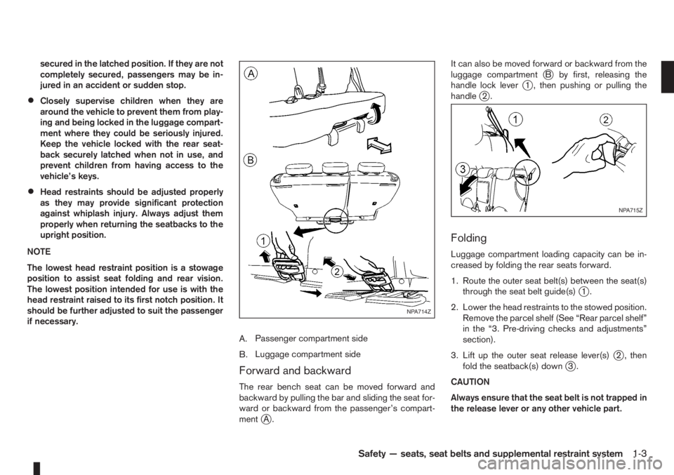
A.Passenger compartment side
B.Luggage compartment side
Forward and backward
The rear bench seat can be moved forward and
backward by pulling the bar and sliding the seat for-
ward or backward from the passenger’s compart-
ment
jA.It can also be moved forward or backward from the
luggage compartment
jB by first, releasing the
handle lock leverj1 , then pushing or pulling the
handlej2.
Folding
Luggage compartment loading capacity can be in-
creased by folding the rear seats forward.
1. Route the outer seat belt(s) between the seat(s)
through the seat belt guide(s)
j1.
2. Lower the head restraints to the stowed position.
Remove the parcel shelf (See “Rear parcel shelf”
in the “3. Pre-driving checks and adjustments”
section).
3. Lift up the outer seat release lever(s)
j2 , then
fold the seatback(s) downj3.
CAUTION
Always ensure that the seat belt is not trapped in
the release lever or any other vehicle part.
NPA714Z
NPA715Z
Safety — seats, seat belts and supplemental restraint system1-3
Page 45 of 235

COMBINATION METER DISPLAY
(LCD)
1.The TRIP button/Steering wheelswitch*
toggles between:
Twin trip odometer setting
TRIP computer setting
2.Clock setting/Oil change schedule setting*
switchA.Clock display
B.Cruise control/Speed limiter display
For further information see “Speed limiter” in
the “5. Starting and driving” section and
“Cruise control system” in the “5. Starting and
driving” section.
C.Outside temperature display
D.Odometer/distance to oil change information*
E.Twin trip odometer/Trip computer mode*
F.Oil level status (HR16DE or K9K engine
equipped models only)
*where fitted
NOTE
The LCD display information comes on only when
the ignition switch is turned to the ON position.
ODOMETER/TWIN TRIP ODOMETER
Odometer
jD
The odometer records the total distance the vehicle
has been drivenjD.
Twin trip odometerjE
The twin trip odometer records the distance of indi-
vidual trips.
The odometer/twin trip odometer is displayed in
jE
when the ignition switch is in the ON position.Changing the display:
Press the TRIP button/Steering wheel
switch
to change the display as follows:
TripA⇒TripB⇒Trip Computer modes (where fit-
ted)
Resetting the trip odometer:
In the Trip A or Trip B mode, press the TRIP button/
Steering wheel
switch for more than 1 second
to reset the trip odometer to zero.
TRIP COMPUTER (where fitted)
When the ignition switch is turned to the ON posi-
tion, modes of the trip computer can be selected by
pressing the TRIP button/Steering wheel
switch.
The following modes can be selected:
•Distance to empty
•Average fuel consumption
•Average speed
•Journey time
Distance to emptym(km or mls)
The distance to empty provides an estimation of the
distance that can be driven before refuelling. The
range is constantly being calculated, based on the
amount of fuel in the fuel tank and the actual fuel
consumption.
The distance to empty includes a low range warning
feature: when the fuel level is low, the distance to
NIC1483
NIC1484
Instruments and controls2-3
Page 46 of 235

empty is automatically selected and the digits blink
in order to draw the driver’s attention. Press the
TRIP button/Steering wheel
switch if you wish
to return to the mode that was selected before the
warning occurred.
When the fuel level drops even lower, the distance
to empty will display
along within a
flashing mode.
Average fuel consumption (l/100 km or
mpg)
The average fuel consumption mode shows the av-
erage fuel consumption since the last reset. The dis-
played average fuel consumption can be reset by
pressing the TRIP button/Steering wheel
switch for more than 1 second.
Average speed (km/h or MPH)
The average speed mode shows the average ve-
hicle speed since the last reset. The displayed aver-
age speed can be reset by pressing the TRIP but-
ton/Steering wheel
switch for more than 1
second.
Journey timem
The journey time mode shows the time since the last
reset in minutes and seconds. The displayed time
can be reset by pressing the TRIP button/Steering
wheel
switch for more than 1 second.
Trip computer reset
Pushing the TRIP button/Steering wheelswitch for more than 3 seconds will reset all modes
except Trip A and distance to empty.
OUTSIDE TEMPERATURE DISPLAY
The outside temperature function provides a displayjC of the outside temperature (ºC) when the ignition
switch is in the ON position.
The display of positive temperatures is unsigned
(blank), negative temperatures are prefixed with a
minus sign.
Low temperature warning
Above 4°C the display remains steady.
The display will flash to indicate a low outside air
temperature, and the possibility of icy or slippery
road conditions:
•When the outside temperature drops between
–3°C and 3°C.
•When starting the vehicle below –3°C.
The temperature display will not flash:
•After approximately 20 seconds, when starting
the vehicle and the outside temperature is below
–3°C.
•When the outside temperature rises from below
–3°C into the range between –3°C and 3°C.
•While driving, when the outside temperature
drops below –3°C.CAUTION
Even if the display is not flashing, there is no
guarantee that the road is free of hazards caused
by inclement weather.
NOTE
The outside air temperature sensor is located at
the front of the vehicle. At low speeds the sensor
can be affected by engine heat, heat reflected
from the road surface and exhaust from other
vehicles, these influences can cause the display
to be inaccurate. To compensate, the outside air
temperature display is designed to react slowly
to increasing temperatures, but quickly to falling
temperatures.
ENGINE OIL LEVEL INFORMATION
(where fitted)
When the ignition is turned to the ON position, dis-
tance to oil change informationand oil level sta-
tus are displayed on the LCD displayjE in the fol-
lowing order:
– Distance to oil change (with a wrench symbol
)
– Oil level status (“Oil Good” or “Oil Lo”)
Only for models with HR16DE or K9K engine.
For details, see “HR16DE or K9K engine oil level
status” later in this section.
After the oil level status (where fitted), the LCD dis-
play switches to the last twin trip odometer/trip com-
2-4Instruments and controls
Page 50 of 235

“Supplemental Restraint System (air bag system)”
in the “1. Safety — seats, seat belts and supple-
mental restraint system” section.
Brake warning light
This light functions for both the handbrake and the
footbrake systems.
Handbrake indicator:
The light comes on when the handbrake is applied.
Low brake fluid warning:
The light warns of a low brake fluid level in the brake
power assist unit. If the light comes on while the
engine is running and the handbrake is not applied,
stop the vehicle and perform the following:
1. Check the brake fluid level. Add brake fluid as
much as necessary. See “Brake and clutch fluid”
in the “8. Maintenance and do-it-yourself” sec-
tion.
WARNING
If the level is below the MIN mark on the brake
fluid reservoir, do not drive until the brake sys-
tem has been checked at a NISSAN dealer or
qualified workshop.
2. If the brake fluid level is correct:
Have the warning system checked by a NISSAN
dealer or qualified workshop.
WARNING
•Driving your vehicle could be dangerous.
Therefore have it towed to the nearest
NISSAN dealer or qualified workshop.
•Pressing the brake pedal with the engine
stopped and/or low brake fluid level could in-
crease your stopping distance and require
greater pedal effort as well as pedal travel.
Charge warning light
If the light comes on while the engine is running, it
may indicate that the charging system is malfunc-
tioning. Turn the engine off and check the alternator
belt. If the belt is loose, broken, missing or if the light
remains on, see a NISSAN dealer or qualified work-
shop immediately.
CAUTION
Do not continue driving if the belt is loose, bro-
ken or missing.
Door open warning light
This light comes on when any of the doors are not
closed securely while the ignition switch is in the
ON position.
Engine coolant temperature
warning light
The engine coolant temperature varies with the out-
side air temperature and driving condition.
When the ignition switch is turned to the ON posi-tion, the engine coolant temperature warning light
illuminates for a few seconds and then goes off.
This means the system is operational.
The engine coolant temperature warning light illumi-
nates when the engine coolant temperature reaches
an excessively high temperature of approximately
105 °C (221 °F).
CAUTION
•If the engine coolant temperature warning
light comes on, stop the vehicle as soon as
safely possible and contact a NISSAN dealer
or qualified workshop.
•When towing a trailer or driving uphill, reduce
the vehicle speed as soon as safely possible
to decrease the engine coolant temperature.
•If the engine overheats, continued operation
of the vehicle may seriously damage the en-
gine. See “Engine overheat” in the “6. In case
of emergency” section for immediate action
required.
WARNING
Do not remove the radiator cap while the engine
is hot. Otherwise, there is a danger of being
scalded by the coolant that is likely to erupt from
the filler.
Engine oil pressure warning light
This light warns of low engine oil pressure. If the
light flickers, comes on during normal driving, or
stays on once the engine is started, pull off the road
2-8Instruments and controls
Page 52 of 235

If the warning light remains illuminated after the en-
gine has been started, there will be no power steer-
ing assistance: the vehicle may be driven using the
mechanical steering system although it is not rec-
ommended as the effort to turn the steering wheel
will be significantly increased compared to normal
operation.
WARNING
•If the EPAS warning light illuminates while
driving, stop as soon as safely possible.
•In certain circumstances, factors external to
the EPAS system may contribute to the illumi-
nation of the warning light. If the warning light
illuminates, stop the vehicle as soon as safely
possible if driving, turn the ignition switch to
the “OFF” position for approximately 20 sec-
onds, then turn the ignition switch to the ON
position again. If the light remains illuminated,
we recommend you to contact a NISSAN
dealer or qualified workshop.
See “Power steering system” in the “5. Starting and
driving” section for further details on the EPAS sys-
tem.
Ignition knob warning light
(Intelligent Key system only)
When the ignition knob is turned to the ON position,
the ignition knob warning light illuminates for a few
seconds and then goes off. This means the system
is operational.The ignition knob warning light warns the driver of
the ignition knob position.
MT models:
The warning light blinks and the buzzer sounds twice
when the ignition knob is turned to the “OFF” posi-
tion. Depress the ignition PUSH release button, then
turn the ignition switch to the LOCK position.
AT models:
The warning light blinks and the buzzer sounds twice
when the ignition knob is turned to the “OFF” posi-
tion. Make sure the selector lever is in the P (Park)
position, then turn the ignition switch to the LOCK
position.
See “Ignition knob (where fitted)” in the “5. Starting
and driving” section for further details.
CAUTION
•The steering wheel can only be locked when
the ignition knob is in the LOCK position. Make
sure the ignition knob is in the LOCK position
before leaving the vehicle.
•The emergency key can only be removed at
the LOCK position. Make sure the ignition
knob is in the LOCK position before removing
the emergency key.
•If the ignition knob warning light comes on
while driving, contact a NISSAN dealer or
qualified workshop for repair.
NATS security indicator light
This light blinks whenever the ignition switch is in
the LOCK or Acc position. This function indicates
that your vehicle is equipped with NISSAN Anti-
Theft System (NATS)*.
If NISSAN Anti-Theft System (NATS)* is malfunc-
tioning, this light will remain on while the ignition
switch is in the ON position.
For additional information, see “NISSAN Anti-Theft
System (NATS)” later in this section.
* Immobilizer
Seat belt warning light and
chime
The light reminds the driver to fasten his/her seat
belt. The light comes on whenever the ignition switch
is turned to the ON position. It goes out whenever
the front seat belt is securely fastened. The chime
will sound unless the front seat belt is securely fas-
tened when the vehicle speed exceeds 25 km/h (15
MPH). The chime will stop after approximately 90
seconds.
NOTE
The front passenger seat belt warning light
comes on the centre console. See “Seat belt
warning lights” in the “1. Safety — seats, seat
belts and supplemental restraint system” section.
2-10Instruments and controls