2012 MINI COUPE ROADSTER CONVERTIBLE warning lights
[x] Cancel search: warning lightsPage 14 of 283

CockpitAT A GLANCE
13
Indicator and warning
lamps
The concept
Indicator and warning lamps can light up in
various combinations and colors in indicator
area 1 or 2.
Some lamps will be tested for proper functioning
when the engine is started or the ignition is
switched on and will therefore light up briefly.
Explanatory text messages
Text messages at the uppe r edge of the Control
Display explain the mean ing of the displayed
indicator and warning lamps. You can call up more information, e.g. on the
cause of a malfunction and on how to respond,
via Check Control, page
77.
In urgent cases, this information will be shown
as soon as the corresponding lamp lights up.
Indicator lamps without text messages
The following indicator lamps in display area 1
indicate certain functions:
High beams/headlamp flasher 98
Front fog lamps 99
Rear fog lamp 99
Lamp flashes:
DSC or DTC is regulating the drive
forces in order to maintain driving
stability 83
Parking brake applied 62
Engine malfunction with adverse effect
on exhaust emissions 226
Cruise control 68
Turn signals 65
00320051004F004C00510048000300280047004C0057004C005200510003
Page 30 of 283

Opening and closingCONTROLS
29
This means that your settings will be activated
for you, even if in the meantime your car was
used by someone else with another remote
control and the corresponding settings.
At most three remote co ntrols can be set for
three different people. A prerequisite is that
each person uses a separate remote control.
Personal Profile settings
For more information on specific settings, refer
to the specified pages.
> Response of the central locking system
when the car is being unlocked 30
> Automatic locking of the vehicle 33
> Triple turn signal activation 65
> Settings for the displays on the onboard
computer, in the speedometer and in the
tachometer:
>12 h/24 h mode of the clock 76
> Date format 77
> Brightness of the Control Display 80
> Language on the Control Display 80
> Units of measure for fuel consumption,
distance covered/re maining distances
and temperature 74
> Light settings:
>Pathway lighting 97
> Daytime running lights 97
> Automatic climate control: activating/
deactivating the AUTO program, setting the
temperature, air volume and air
distribution 103
> Entertainment:
>Tone control 147
> Adjusting vo lume levels 147
Central locking system
The concept
The central locking system is ready for operation
whenever the driver's door is closed.
The system simultaneously engages and
releases the locks on the following:
>Doors
> Tailgate
> Fuel filler flap
Operating from outside
>Via the remote control
> Using the door lock
> In cars with Comfor t Access, via the door
handles on the driver's and passenger's
sides
The anti-theft system is also operated at the
same time. It prevents the doors from being
unlocked using the lock buttons or door han-
dles. The remote control can also be used to
switch on/off the welcome lamps and interior
lamps. The alarm system is also activated or
deactivated, page 34.
Operating from inside
Button for central locking system, page 32.
In the event of a sufficiently severe accident,
the central locking system unlocks automati-
cally. In addition, the hazard warning flashers
and interior lamps come on.
Opening and closing:
from outside
Persons or animals in a parked vehicle
could lock the doors from the inside. Take
the key with you when you leave the vehicle
so that the vehicle can be opened from the
outside. <
00320051004F004C00510048000300280047004C0057004C005200510003
Page 39 of 283

CONTROLSOpening and closing
38
Warning lamps
The warning lamp lights up when an
attempt is made to start the engine: the
engine cannot be started. The remote
control is not inside the vehicle or is malfunc-
tioning. Take the remote control with you inside
the vehicle or have it checked. If necessary,
insert another remote co ntrol into the ignition
lock.
The warning lamp lights up when the
engine is running: the remote control is
no longer inside the vehicle. After the
engine is switched off, the engine can only be
restarted within approx. 10 seconds.
The indicator lamp comes on and a
message appears on the Control
Display: replace the battery in the
remote control.
Replacing the battery
The remote control for Comfort Access contains
a b a t t e r y t h a t w i l l n e e d t o b e r e p l a c e d f r o m t i m e
to time.
1. Remove the cover.
2. Insert the new battery with the plus side
facing up.
3. Press the cover on to close.
Take the old battery to a recycling center
or to your MINI dealer. <
Windows
To prevent injuries, exercise care when
closing the windows.
Take the remote control with you when you
leave the car; otherwise, children could operate
the electric windows and possibly injure
themselves. <
If, after a window is opened and closed
several times in close succession, the
window can only be closed and not opened, the
system is overheated. Le t the system cool for
several minutes with the ignition switched on or
the engine running. <
Opening
>Press the swit ch downward.
The window opens until you release the
switch.
> Push the switch downward.
As of radio readiness, the windows will open
automatically. Push the switch again to stop
the opening movement.
To open the window a crack, press the switch
down twice in quick succession.
Closing
In order to close the window, press the switch
up. The window closes until you release the
switch.
00320051004F004C00510048000300280047004C0057004C005200510003
Page 70 of 283

DrivingCONTROLS
69
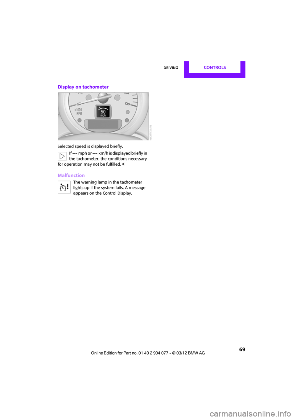
Display on tachometer
Selected speed is displayed briefly.If --- mph or --- km/h is displayed briefly in
the tachometer, the conditions necessary
for operation may not be fulfilled.<
Malfunction
The warning lamp in the tachometer
lights up if the system fails. A message
appears on the Control Display.
00320051004F004C00510048000300280047004C0057004C005200510003
Page 72 of 283

Controls overviewCONTROLS
71
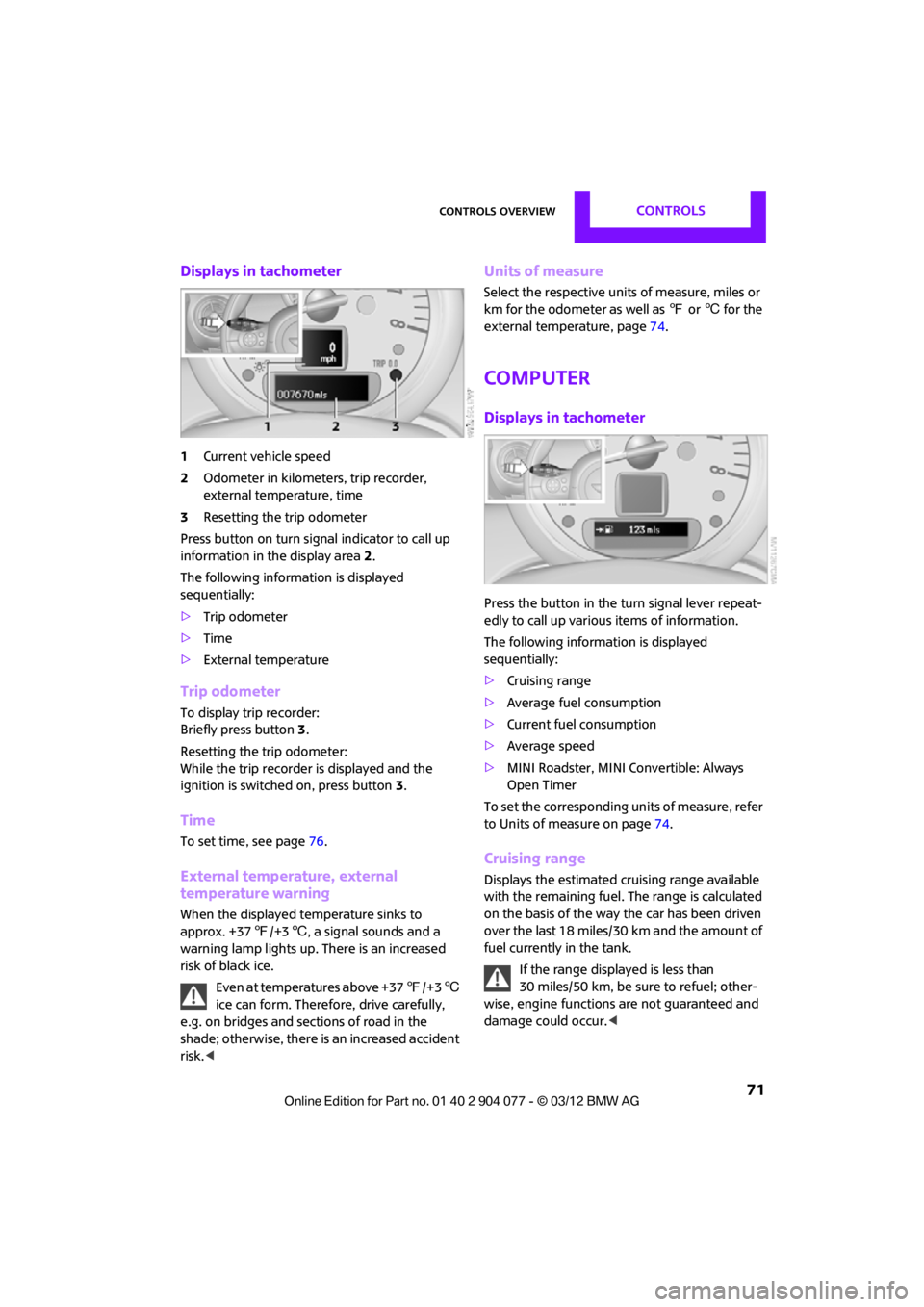
Displays in tachometer
1Current vehicle speed
2 Odometer in kilometers, trip recorder,
external temperature, time
3 Resetting the trip odometer
Press button on turn signal indicator to call up
information in the display area 2.
The following information is displayed
sequentially:
> Trip odometer
> Time
> External temperature
Trip odometer
To display trip recorder:
Briefly press button 3.
Resetting the trip odometer:
While the trip recorder is displayed and the
ignition is switched on, press button 3.
Time
To set time, see page 76.
External temperature, external
temperature warning
When the displayed temperature sinks to
approx. +37 7/+3 6, a signal sounds and a
warning lamp lights up. There is an increased
risk of black ice.
Even at temperatures above +37 7/+3 6
ice can form. Therefore, drive carefully,
e.g. on bridges and sections of road in the
shade; otherwise, there is an increased accident
risk. <
Units of measure
Select the respective units of measure, miles or
km for the odometer as well as 7 or 6 for the
external temperature, page 74.
Computer
Displays in tachometer
Press the button in the turn signal lever repeat-
edly to call up variou s items of information.
The following information is displayed
sequentially:
> Cruising range
> Average fuel consumption
> Current fuel consumption
> Average speed
> MINI Roadster, MINI Convertible: Always
Open Timer
To set the corresponding units of measure, refer
to Units of measure on page 74.
Cruising range
Displays the estimated cruising range available
with the remaining fuel. The range is calculated
on the basis of the way the car has been driven
over the last 18 miles/30 km and the amount of
fuel currently in the tank.
If the range displayed is less than
30 miles/50 km, be sure to refuel; other-
wise, engine functions are not guaranteed and
damage could occur.<
00320051004F004C00510048000300280047004C0057004C005200510003
Page 83 of 283

CONTROLSTechnology for driving comfort and safety
82
Technology for driving comfort
and safety
Vehicle equipment
In this chapter, all production, country, and
optional equipment that is offered in the model
range is described. Equipment is also described
that is not available because of, for example,
selected options or coun try version. This also
applies to safety relate d functions and systems.
Park Distance Control
PDC
The concept
PDC assists you with parking in reverse. Acoustic
signals and a visual indi cator warn you of the
presence of an object behind the vehicle. To
measure the distance, there are four ultrasonic
sensors in either bumper.
These sensors have a range of approx. 6.5 ft/
2m. However, an acoust ic warning does not
sound until an object is approx. 24 in/60 cm
from the rear corner sensors, or approx. 5 ft/
1.50 m from the rear center sensors.
PDC is a parking aid that can indicate
objects when they are approached slowly,
as is usually the case when parking. Avoid
approaching an object at high speed; otherwise,
physical circumstances ma y lead to the system
warning being issued too late. <
Automatic mode
With the engine running or the ignition switched
on, the system is activated automatically after
approx. 1 second when you engage reverse
gear or move the automatic transmission selec-
tor lever to position R. Wait this short period
before driving.
Acoustic signals
As the distance between vehicle and object
decreases, the intervals between the tones
become shorter. If the distance to the nearest
object falls to below roughly 1 ft/30 cm, then a
continuous tone sounds.
If the distance remains co nstant, e.g. when driv-
ing parallel to a wall, the acoustic signal stops
after approx. 3 seconds.
Malfunction
Indicator lamp lights up. PDC has failed.
A message appears on the Control
Display. Have the system checked.
To avoid this problem, keep the sensors clean
and free of ice or snow in order to ensure that
they will continue to operate effectively. When
using a high-pressure cleaner, do not direct the
jet toward the sensors for lengthy periods and
only spray from a distance of at least 4 in/10 cm.
PDC with visual warning
To have the system show distances to objects on
the Control Display. The contours of distant
objects are shown on the Control Display even
before the acoustic sign al sounds. The display
appears on the Control Display as soon as the
transmission is shifted into reverse or the
selector lever is moved into the R position.
System limitations
Even with PDC, final responsibility for esti-
mating the distance between the vehicle
and any obstructions always remains with the
driver. Sensors, too, have blind spots in which
objects cannot be dete cted. Moreover, ultra-
sonic detection can reach its physical limits with
objects such as trailer tow bars and couplings,
thin and wedge-shaped objects, etc. Low
objects already indicated, such as curbs, may
00320051004F004C00510048000300280047004C0057004C005200510003
Page 92 of 283

Technology for driving comfort and safetyCONTROLS
91
Continued driving with a flat tire
When driving with a damaged tire:
1.Avoid sudden braking and steering
maneuvers.
2. Do not exceed a speed of 50 mph/80 km/h.
3. At the next opportunity, check the air
pressure in all four tires.
If the inflation pressure is correct in all four
tires, then the Tire Pressure Monitor may not
have been reset. The system must then be
reset.
Possible driving distance with complete loss of
tire inflation pressure:
The distance it is possible to drive with a flat tire
depends on the load and the stress on the vehi-
cle while driving.
With an average load, it may be possible to drive
for approx. 50 miles/80 km.
When driving with damaged tires, the handling
characteristics change, e. g. the vehicle will skid
sooner when braking, braking distances will be
longer, or self-steering response will change.
Adapt your driving style accordingly. Avoid turn-
ing abruptly and driving over obstacles such as
curbs, potholes, etc.
Since the possible driving distance depends to a
considerable degree on the strain exerted on
the vehicle while driving, it can be shorter or,
with a gentle dr iving style, can also be longer,
depending on the speed, road condition, exter-
nal temperature, vehicle load, etc.
Drive cautiously and do not exceed a
speed of 50 mph/80 km/h.
A loss of tire inflation pr essure results in a change
in the handling characteristics, e.g. reduced lane
stability during braking, a longer braking dis-
tance and altered self-steering properties. <
Vibrations or loud noises while driving can
indicate complete failure of the tire.
Reduce your speed and bring the vehicle to a
stop; otherwise, pieces of tire may come off,
which could result in an accident. Do not con-
tinue driving and contact your MINI dealer. <
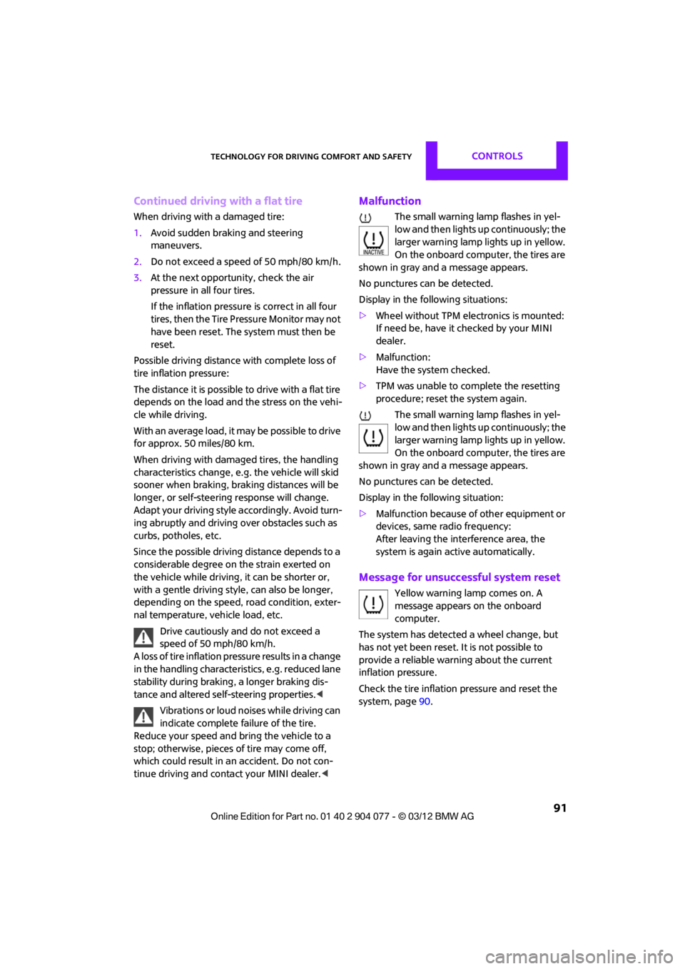
Malfunction
The small warning lamp flashes in yel-
low and then lights up continuously; the
larger warning lamp lights up in yellow.
On the onboard computer, the tires are
shown in gray and a message appears.
No punctures can be detected.
Display in the following situations:
> Wheel without TPM electronics is mounted:
If need be, have it checked by your MINI
dealer.
> Malfunction:
Have the system checked.
> TPM was unable to complete the resetting
procedure; reset the system again.
The small warning lamp flashes in yel-
low and then lights up continuously; the
larger warning lamp lights up in yellow.
On the onboard computer, the tires are
shown in gray and a message appears.
No punctures can be detected.
Display in the following situation:
> Malfunction because of other equipment or
devices, same radio frequency:
After leaving the inte rference area, the
system is again active automatically.
Message for unsuccessful system reset
Yellow warning lamp comes on. A
message appears on the onboard
computer.
The system has detected a wheel change, but
has not yet been reset. It is not possible to
provide a reliable warn ing about the current
inflation pressure.
Check the tire inflation pressure and reset the
system, page 90.
00320051004F004C00510048000300280047004C0057004C005200510003
Page 95 of 283

CONTROLSTechnology for driving comfort and safety
94
so that the front passenger airbags are activated
and the indicator lamp goes out. If the desired
airbag status cannot be achieved by changing
the sitting position, transport the relevant pas-
senger on a rear seat. Do not attach covers,
cushions, ball mats or other items to the front
passenger seat unless they are specifically rec-
ommended by the manufacturer of your MINI.
Do not place items unde r the seat which could
press against the seat from below. Otherwise, a
correct analysis of th e seat cushion is not
ensured. <
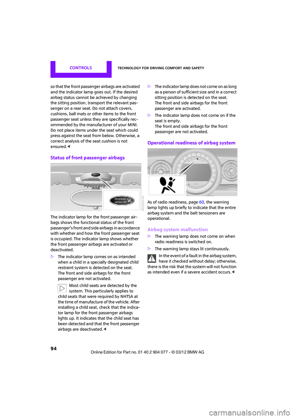
Status of front passenger airbags
The indicator lamp for the front passenger air-
bags shows the functional status of the front
passenger's front and side airbags in accordance
with whether and how the front passenger seat
is occupied. The indica tor lamp shows whether
the front passenger airbags are activated or
deactivated.
> The indicator lamp co mes on as intended
when a child in a spec ially designated child
restraint system is detected on the seat.
The front and side airbags for the front
passenger are not activated.
Most child seats are detected by the
system. This particularly applies to
child seats that were required by NHTSA at
the time of manufacture of the vehicle. After
installing a child seat, check that the indica-
tor lamp for the front passenger airbags
lights up. It indicates that the child seat has
been detected and that the front passenger
airbags are deactivated. <>
T h e i n d i c a t o r l a m p d o e s n o t c o m e o n a s l o n g
as a person of sufficient size and in a correct
sitting position is detected on the seat.
The front and side airbags for the front
passenger are activated.
> The indicator lamp does not come on if the
seat is empty.
The front and side airbags for the front
passenger are not activated.
Operational readines s of airbag system
As of radio readiness, page 60, the warning
lamp lights up briefly to indicate that the entire
airbag system and the belt tensioners are
operational.
Airbag system malfunction
> The warning lamp does not come on when
radio readiness is switched on.
> The warning lamp stays lit continuously.
In the event of a fault in the airbag system,
have it checked without delay; otherwise,
there is the risk that the system will not function
as intended even if a severe accident occurs. <
00320051004F004C00510048000300280047004C0057004C005200510003