Page 169 of 218

MOBILITYReplacing components
168
Turn signals, parking lamps, roadside
parking lamps, and fog lamps
Accessing the lamps via the wheel well
1Turn signal
2 Parking/roadside parking/fog lamps
Replacing a turn signal bulb
21 watt bulb, PY 21 W
1.Turn in the wheel.
2. Remove cover 1.
To do so, turn the cover counterclockwise.
3. Remove the inside cover.
To do so, turn the cover counterclockwise.
4. Unscrew the bulb counterclockwise. 5.
To insert the new bulb and replace the
covers, proceed in reverse order.
Replacing a parking/roadside parking
lamp bulb
5 watt bulb, W 5 W
1.Turn in the wheel.
2. Remove cover 2.
To do so, turn the cover counterclockwise.
3. Unscrew the upper bulb counterclockwise.
4. To insert the new bulb and replace the
cover, proceed in reverse order.
Replacing a fog lamp bulb
H8 bulb, 35 watts
1.Turn in the wheel.
2. Remove cover 2.
To do so, turn the cover counterclockwise.
3. Pull the cable connector.
4. Unscrew the lower bulb counterclockwise.
5. To insert the new bulb and replace the
cover, proceed in reverse order.
Online Edition for Part no. 01 40 2 914 786 - \251 07/12 BMW AG
Page 170 of 218
Replacing componentsMOBILITY
169
Side turn signals
5watt bulb, W5W
1.Push the lamp with the ventilation grate
forward and remove.
2. Unscrew the bulb holder counterclockwise.
3. Pull out and replace the bulb.
4. To insert the new bulb and replace the
cover, proceed in reverse order.
Tail lamps
Turn signals: 21 watt bulb, PY 21 W
Brake light: bulb 21 Watt/5 Watt, W 5 W
Other lights: bulb 21 Watt, P 21 W
1Turn signal
2 Tail lamp LED
3 Brake light
Changing
1.Remove the cover from the sidewall of the
cargo area.
MINI Coupe, MINI Roadster:
MINI Convertible:
Move the convertible top to its uppermost
position, refer to Loading aid page 109, and
remove the cover of the luggage compart-
ment side wall.
2. Unscrew the desired bulb counterclockwise,
arrows 1.
Another bulb is located behind the luggage
compartment side wall, arrow 2.
3. To insert the new bulb and replace the
cover, proceed in reverse order.
Online Edition for Part no. 01 40 2 914 786 - \251 07/12 BMW AG
Page 171 of 218

MOBILITYReplacing components
170
Rear fog lamps/Reverse lights
Bulbs 16 Watt, W 16W
Access the lamps via the rear or underside of the
bumper.
1.Press fastening clips, arrows, together and
remove the lamp holder.
2. Remove the bulb and replace it.
3. To insert the new bulb and bulb holder,
proceed in reverse order.
4. Re-engage the bulb holder so that it audibly
clicks into place.
John Cooper Works: aerodynamic
bumper
Access the lamps via the rear or underside of the
bumper.
1.Unscrew the bulb holder counterclockwise,
arrow.
2. Remove the bulb and replace it.
3. To insert the new bulb and bulb holder,
proceed in reverse order.
License plate lamps
5 watt bulb, C 5 W
1.Using a screwdriver, push the lamp to the
left in the tab of the lamp housing, arrow 1.
2. Remove the lamp, arrow 2 .
3. Replace the bulb.
4. Insert the lamp.
Center brake lamp
This lamp uses LED technology for operation. In
the event of a malfunction, contact your MINI
dealer or a workshop that has specially trained
personnel working in accordance with the
specifications of your MINI manufacturer.
Repairing a flat tire
Safety measures in the event of a break-
down:
Park the vehicle as far as possible from moving
traffic and switch on the hazard warning
flashers.
Turn the steering wheel until the front wheels
are in the straight-ahead position and engage
the steering wheel lock. Engage the parking
brake and shift into 1st or reverse gear or place
the selector lever in position P.
All passengers should be outside the vehicle and
in a safe place, e.g. behind a guardrail.
Erect a warning triangle or warning flasher at the
appropriate distance if necessary. Comply with
all safety guidelines and regulations. <
Online Edition for Part no. 01 40 2 914 786 - \251 07/12 BMW AG
Page 172 of 218

Replacing componentsMOBILITY
171
In the event of a flat tire, different procedures
should be followed depending on the equip-
ment included in your vehicle:
>MINI Mobility Kit, refer to the following
section
> Run-flat tires, page 173
> Tire change with space-saver spare tire,
page 173
MINI Mobility Kit
Preparations
Use of the MINI Mobility Kit may be ineffective if
the tire puncture meas ures approx. 1/8 in/4 mm
or more. Contact the nearest MINI dealer if the
tire cannot be made driv able with the Mobility
Kit.
Do not remove foreign bodies which have
penetrated the tire if possible.
Follow the instructions on using the
Mobility Kit found on the compressor
and the sealant bottle. <
Remove the adhesive label for the speed limit
from the sealant bottle and affix it to the
steering wheel.
Sealant and compressor
1 Sealant bottle and adhesi ve label with speed
limit
2 Filling hose
Note the use-by date on the sealant
bottle. < 3
Holder for the sealant bottle
4 Compressor
5 Plug and cable for the socket in the vehicle
interior, page 101
6 Connection hose to connect the compressor
and sealant bottle or the compressor and
wheel
7 On/off switch
8 Pressure gauge for indicating the tire
inflation pressure
9 Release button for reduci ng the tire inflation
pressure
Connector, cable and connection hose are
stored in the compressor housing.
Using the Mobility Kit
To repair a tire puncture with the Mobility Kit,
proceed as follows:
> Filling the tire with sealant.
> Distributing the sealant.
> Correct the tire inflation pressure.
Filling the tire with sealant.
Proceed in the specified order; otherwise,
sealant may emerge under high pres-
sure. <
1. Shake the sealant bottle.
2. Pull the connecting hose 6 completely out of
the compressor housing and screw it onto
the connector of the sealant bottle. Make
sure that the hose is not kinked.
3. Insert the sealant bottle on the compressor
housing in an upright position.
Online Edition for Part no. 01 40 2 914 786 - \251 07/12 BMW AG
Page 173 of 218

MOBILITYReplacing components
172
4.Unscrew the dust cap from the valve of the
defective wheel and screw the filling hose 2
of the sealant bottle onto the valve.
5. Ensure that the compre ssor is switched off.
6. Insert the plug 5 into the lighter socket/
power socket in the vehicle interior,
page 102.
7. With the engine running:
Switch on the compressor and let run for
about 3 to 8 minutes in order to add the
sealant and to achieve an inflation pressure
of about 1.8 bar/26 psi.
When adding the sealant, the filling
pressure can temporarily increase up
to about 5 bar/73 psi. Do not switch off the
compressor during this phase. <
Do not run the comp ressor for longer
than 10 minutes; otherwise, the
device will overheat and possibly be
damaged.<
8. Switch off the compressor.
If an inflation pressure of 1.8 bar/26 psi is not
reached:
1. Unscrew the filling hose 2 from the wheel
and drive the vehicle forward and backward
approx. 33 ft/10 m to distribute the liquid
sealant in the tire evenly.
2. Inflate the tire again with the compressor.
If an inflation pressure of 1.8 bar/26 psi is
not reached, then the tire is too badly
damaged. Please contact the nearest MINI
dealer. <
Stowing Mobility Kit
1.Unscrew filler hose 2 of the sealant bottle
from the wheel.
2. Unscrew connecting hose of the
compressor 6 from the sealant bottle.
3. Connect the filler hose 2 of the sealant
bottle to the unoccupied connection on
the sealant bottle.
This prevents the rest of the sealant from
escaping from the bottle.
4. Wrap the empty sealant bottle in suitable
material to avoid dirtying the cargo area.
5. Stow Mobility Kit back in the vehicle.
Distributing the sealant.
Immediately drive appr ox. 3.1 miles/5 km so
that the sealant evenly distributes itself.
Do not exceed speeds of 50 mph/
80 km/h.
If possible, do not drop below 10 mph/
20 km/h. <
Adjusting the tire pressure
1.After driving approx. 3.1 miles/5 km or
10 minutes, stop at a suitable location.
2. Screw the connection hose 6 of the com-
pressor directly onto the tire valve.
3. Insert the plug 5 into the power socket in
the vehicle interior.
4. Adjust tire pressure to 1.8 bar/26 psi. With
the engine running:
> To increase the inflatio n pressure: switch on
the compressor. To ch eck the current infla-
tion pressure, switch off the compressor.
Do not run the compressor for longer
than 10 minutes; otherwise, the
device will overheat and possibly be
damaged. <
> To decrease the inflat ion pressure: press the
release button 9.
Online Edition for Part no. 01 40 2 914 786 - \251 07/12 BMW AG
Page 174 of 218

Replacing componentsMOBILITY
173
If the tire cannot maintain the inflation
pressure, drive the vehicle again, refer to
Distributing the sealan t. Then repeat steps
1to4.
If an inflation pressure of 1.8 bar/26 psi still
cannot be reached, then the tire is too heavily
damaged. Contact your nearest MINI dealer. <
Driving on
Do not exceed the permitted maximum
speed of 50 mph/80 km/h; doing so may
result in an accident. <
Replace the defective tire as soon as possible
and have the new wheel/tire assembly
balanced.
Have the Mobility Kit refilled.
Changing wheels
Run-flat tires
Tire change for run-flat tires:
> Prepare for tire change, page 174
> Jack up vehicle, page 174
> Tighten lug bolts, page 175
Space-saver spare tire
Tire change with space-saver spare tire:
>Remove the space-saver spare tire,
page 173
> Prepare for tire change, page 174
> Jack up vehicle, page 174
> Mount space-saver spare tire, page 175
> Tighten lug bolts, page 175
> Drive with space-saver spare tire, page 174
Removing the space-saver spare tire
The screw connection of the space-saver spare
tire is under the floor mat in the cargo area, on
the base of the storage compartment for the tire
change set. 1.
Unscrew the screw connection with the
special wrench.
2. Take out the cover panel.
3. Screw the lifting handle from the toolkit onto
the thread.
4. Raise the lifting handle slightly.
5. Squeeze the securing spring.
6. The space-saver spare tire is released and
must be held by the lifting handle.
7. Lower the space-saver spare tire with the
lifting handle.
8. Unscrew the lifting handle.
Online Edition for Part no. 01 40 2 914 786 - \251 07/12 BMW AG
Page 175 of 218

MOBILITYReplacing components
174
9.Pull the space-saver spare tire underneath
the vehicle out toward the rear.
10. Position the space-save r spare tire with the
valve facing upward.
11. Unscrew the valve extension from the valve
of the space-saver spare tire.
12. Unscrew the dust cap from the extension
and place it on the valve of the space-saver
spare tire.
Due to its different dimensions, the
damaged wheel cannot be placed in the
recess for the space-saver spare tire. <
Driving with the space-saver spare tire
Drive cautiously and do not exceed a
speed of 50 mph/80 km/h. Changes may
occur in vehicle handling such as lower track
stability during braking, longer braking dis-
tances and changes in self-steering properties
when close to the handling limit. These proper-
ties are more noticeable with winter tires. <
Only one space-saver spare tire may be
mounted at one time. Mount a wheel and
tire of the original size as soon as possible, to
avoid any safety risks. <
Check the tire inflat ion pressure at the
earliest opportunity an d correct it if neces-
sary. Replace the defective tire as soon as possi-
ble and have the new wheel/tire assembly bal-
anced. <
Preparing for a tire change
Observe the safety precautions regarding
flat tires on page 170.< Additional safety measures when
changing tires:
Only change the tire wh en parked on a surface
that is level, firm and not slippery.
The vehicle or the jack could slip sideways on
soft or slippery support surfaces, such as snow,
ice, flagstones, etc.
Do not use a wooden block or similar object as a
support base for the jack, as this would prevent
it from extending to its full support height and
reduce its load-carrying capacity.
Do not lie under the vehicle or start the engine
when the vehicle is supported by the jack; other-
wise, there is a risk of fatal injury. <
1. Place the foldable chock behind the front
wheel on the other side of the vehicle or in
front of the wheel if the vehicle is on an
incline. If the wheel is changed on a surface
with a more severe sl ope, take additional
precautions to secure the vehicle from
rolling.
2. Uncover the lug bolts if necessary.
3. Loosen the lug bolts by a half turn.
Jacking up the vehicle
The vehicle jack is designed for changing
wheels only. Do not attempt to raise
another vehicle model with it or to raise any load
of any kind. To do so could cause accidents and
personal injury. <
1. Place the jack at the jacking point closest to
the wheel.
Online Edition for Part no. 01 40 2 914 786 - \251 07/12 BMW AG
Page 176 of 218

Replacing componentsMOBILITY
175
The jack base must be perpendicular to the
surface beneath the jacking point.
2. During jacking up, insert the jack head in the
square recess of the jacking point.
3. Jack the vehicle up until the wheel you are
changing is raised off the ground.
Mounting the space-saver spare tire
1.Unscrew the lug bolts and remove the
wheel.
2. Remove accumulations of mud or dirt from
the mounting surfaces of the wheel and
hub. Clean the lug bolts.
3. Lift the new wheel into place.
4. Screw at least two lug bolts finger-tight into
opposite bolt holes.
5. Screw in the remaining bolts.
6. Tighten all the lug bolts firmly in a diagonal
pattern.
7. Lower the vehicle.
8. Remove the jack.
Tightening the lug bolts
Tighten the lug bolts in a diagonal pattern.
Immediately have the wheels checked
with a calibrated torque wrench to ensure
that the lug bolts are firmly seated. Otherwise,
incorrectly tightened lug bolts can present a
safety hazard. <
Tightening torque: 103.3 lb ft or 140 Nm.
Replace the defective tire as soon as possible
and have the new wheel/tire assembly
balanced.
Vehicle battery
Maintenance
The battery is maintenance-free; that is, the
electrolyte will last for the life of the battery
when the vehicle is operated in a temperate
climate.
Battery replacement
Only use vehicle batteries that have been
approved for your vehicle by the manu-
facturer; otherwise, the vehicle could be
damaged and systems or functions may not
be fully available. <
After a battery replacement, have the battery
registered on the vehicle by your MINI dealer to
ensure that all convenie nce functions are fully
available and, if nece ssary, the corresponding
Check Control messages are no longer dis-
played.
Charging the battery
Note
Do not connect battery chargers to the
sockets installed in the vehicle at the
factory; otherwise you may cause damage to
the battery. <
Only charge the battery in the vehicle when
the engine is off. Connections, refer to Jump-
starting on page 177.
General information
To guarantee the full service life of the battery,
ensure that the battery is always properly
charged.
It may be necessary to charge the battery in the
following situations:
>If frequent short trips are taken.
> If the vehicle is frequently parked for more
than a month.
Online Edition for Part no. 01 40 2 914 786 - \251 07/12 BMW AG
 1
1 2
2 3
3 4
4 5
5 6
6 7
7 8
8 9
9 10
10 11
11 12
12 13
13 14
14 15
15 16
16 17
17 18
18 19
19 20
20 21
21 22
22 23
23 24
24 25
25 26
26 27
27 28
28 29
29 30
30 31
31 32
32 33
33 34
34 35
35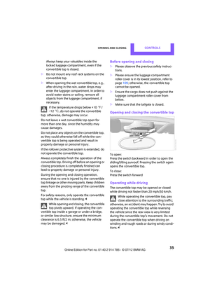 36
36 37
37 38
38 39
39 40
40 41
41 42
42 43
43 44
44 45
45 46
46 47
47 48
48 49
49 50
50 51
51 52
52 53
53 54
54 55
55 56
56 57
57 58
58 59
59 60
60 61
61 62
62 63
63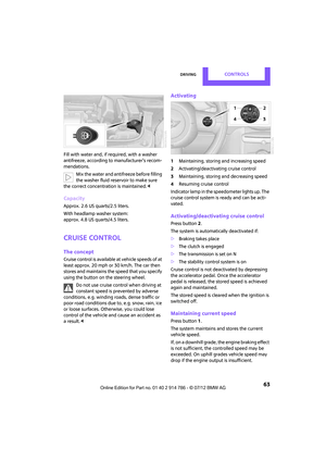 64
64 65
65 66
66 67
67 68
68 69
69 70
70 71
71 72
72 73
73 74
74 75
75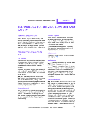 76
76 77
77 78
78 79
79 80
80 81
81 82
82 83
83 84
84 85
85 86
86 87
87 88
88 89
89 90
90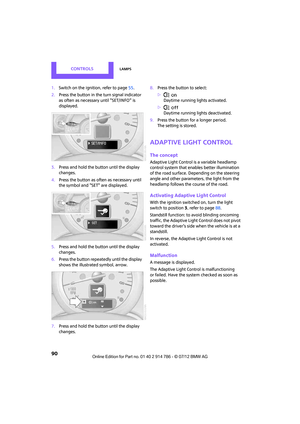 91
91 92
92 93
93 94
94 95
95 96
96 97
97 98
98 99
99 100
100 101
101 102
102 103
103 104
104 105
105 106
106 107
107 108
108 109
109 110
110 111
111 112
112 113
113 114
114 115
115 116
116 117
117 118
118 119
119 120
120 121
121 122
122 123
123 124
124 125
125 126
126 127
127 128
128 129
129 130
130 131
131 132
132 133
133 134
134 135
135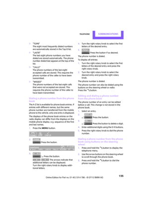 136
136 137
137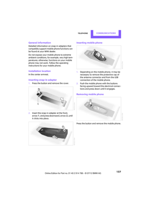 138
138 139
139 140
140 141
141 142
142 143
143 144
144 145
145 146
146 147
147 148
148 149
149 150
150 151
151 152
152 153
153 154
154 155
155 156
156 157
157 158
158 159
159 160
160 161
161 162
162 163
163 164
164 165
165 166
166 167
167 168
168 169
169 170
170 171
171 172
172 173
173 174
174 175
175 176
176 177
177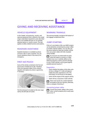 178
178 179
179 180
180 181
181 182
182 183
183 184
184 185
185 186
186 187
187 188
188 189
189 190
190 191
191 192
192 193
193 194
194 195
195 196
196 197
197 198
198 199
199 200
200 201
201 202
202 203
203 204
204 205
205 206
206 207
207 208
208 209
209 210
210 211
211 212
212 213
213 214
214 215
215 216
216 217
217