2012 MERCEDES-BENZ SLK ROADSTER height
[x] Cancel search: heightPage 93 of 321
Backrest angle
X
Relieve the pressure on the backrest.
X Pull handle ;and adjust the backrest to
the desired angle.
X Release handle ;again.
The backres tmust audibly engage.
Sea theight X
Pull handle =upwards or push it down
repeatedly until the seat has reached the
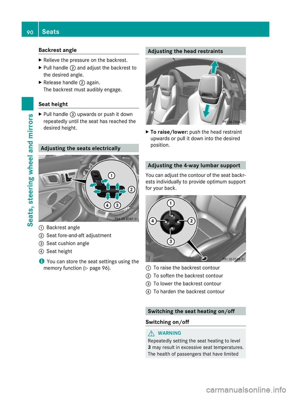
desired height. Adjusting the seats electrically
:
Backrest angle
; Seat fore-and-aft adjustment
= Seat cushion angle
? Seat height
i You can store the seat settings using the
memory function (Y page 96). Adjusting the head restraints
X
To raise/lower: push the head restraint
upwards or pull it down into the desired
position. Adjusting the 4-way lumbar support
You can adjus tthe contour of the seat backr-
ests individually to provide optimum support
for your back. :
To raise the backrest contour
; To soften the backrest contour
= To lower the backrest contour
? To harden the backrest contour Switching the seat heating on/off
Switching on/off G
WARNING
Repeatedly setting the seat heating to level
3 may result in excessive seat temperatures.
The health of passengers that have limited 90
SeatsSeats, steering wheel and mirrors
Page 95 of 321
X
Make sure that the key is in position 2in
the ignition lock.
X To activate: press button :.
Three red indicator lamps in the button light
up. The blower starts up after a preheating
phase of seven seconds.
X Press button :repeatedly until the
desired heating level is set.
X To switch off: press button:repeatedly
until all the indicator lamps go out.
i The blower continues running for seven
seconds to cool down the heating ele-
ments.
i If the battery voltage is too low, AIRSCARF
may switch off.
Problems with AIRSCARF AIRSCARF has switched off prematurely or
will not switch on. The vehicle's electrical sys-
tem voltage is too low because too many
electrical consumers are switched on.
X Switch off electrical consumers which you
do not need, such as the rear window heat-
ing or interior lighting.
X Switch on AIRSCARF again. Steering wheel
Important safety notes
G
WARNING
The electrically adjustable steering wheel can
still be adjusted when there is no key in the
ignition lock. Therefore, do not leave children
unsupervised in the vehicle, as they could
become trapped if the steering wheel is adjus-
ted. G
WARNING
Only adjust the steering wheel when the vehi-
cle is stationary and do not pull away until the
steering wheel adjustment mechanism is
locked in position. You might otherwise drive
without the steering wheel adjustment mech- anism being locked in position. As a result,
you could be distracted from road and traffic
conditions by an unintentional movement of
the steering wheel and thereby cause an acci-
dent.
However, the steerability of the vehicle is not
affected.
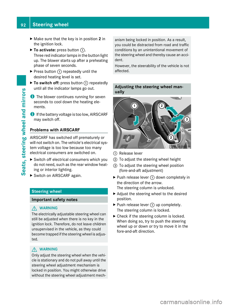
Adjusting the steering wheel man-
ually
:
Release lever
; To adjust the steering wheel height
= To adjust the steering wheel position
(fore-and-aft adjustment)
X Push release lever :down completely in
the direction of the arrow.
The steering column is unlocked.
X Adjust the steering wheel to the desired
position.
X Push release lever :up completely.
The steering column is locked.
X Check if the steering column is locked.
When doing so, try to push the steering
wheel up or down or try to move it in the
fore-and-aft direction. 92
Steering wheelSeats, steering wheel and mirrors
Page 96 of 321
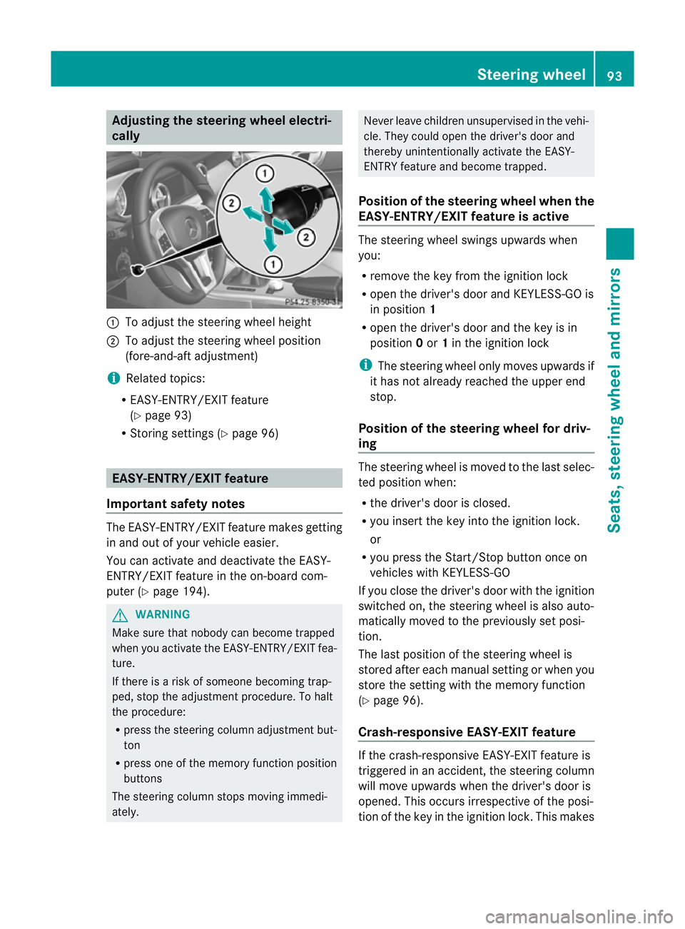
Adjusting the steering wheel electri-
cally :
To adjust the steering wheel height
; To adjust the steering wheel position
(fore-and-aft adjustment)
i Related topics:
R EASY-ENTRY/EXIT feature
(Y page 93)
R Storing settings (Y page 96) EASY-ENTRY/EXIT feature
Important safety notes The EASY-ENTRY/EXIT feature makes getting
in and out of your vehicle easier.
You can activate and deactivate the EASY-
ENTRY/EXIT feature in the on-board com-
puter (Y page 194). G
WARNING
Make sure that nobody can become trapped
when you activate the EASY-ENTRY/EXIT fea-
ture.
If there is a risk of someone becoming trap-
ped, stop the adjustmen tprocedure. To halt
the procedure:
R press the steering colum nadjustment but-
ton
R press one of the memory function position
buttons
The steering column stops moving immedi-
ately. Never leave children unsupervised in the vehi-
cle. They could open the driver's door and
thereby unintentionally activate the EASY-
ENTRY feature and become trapped.
Position of the steering wheel when the
EASY-ENTRY/EXIT feature is active The steering wheel swings upwards when
you:
R
remove the key from the ignition lock
R open the driver's door and KEYLESS-GO is
in position 1
R open the driver's door and the key is in
position 0or 1in the ignition lock
i The steering wheel only moves upwards if
it has not already reached the upper end
stop.
Position of the steering wheel for driv-
ing The steering wheel is moved to the last selec-
ted position when:
R
the driver's door is closed.
R you insert the key int othe ignition lock.
or
R you press the Start/Stop button once on
vehicles with KEYLESS-GO
If you close the driver's door with the ignition
switched on, the steering wheel is also auto-
matically moved to the previously set posi-
tion.
The last position of the steering wheel is
stored after each manual setting or when you
store the setting with the memory function
(Y page 96).
Crash-responsive EASY-EXIT feature If the crash-responsive EASY-EXIT feature is
triggered in an accident, the steering column
will move upwards when the driver's door is
opened. This occurs irrespective of the posi-
tion of the key in the ignition lock. This makes Steering wheel
93Seats, steering wheel and mirrors Z
Page 173 of 321
Problems with PARKTRONIC
Problem Possible causes/consequences and
M Solutions
Only the red segments
in the PARKTRONIC
warning displays are lit.
You also hear a warning
tone for approximately
two seconds.
PARKTRONIC is deacti-
vated after approx-
imately 20 seconds,
and the indicator lamp
in the PARKTRONIC
button lights up. PARKTRONIC has malfunctioned and has switched off.
X
If problems persist, have PARKTRONIC checked at a qualified
specialist workshop. Only the red segments
in the PARKTRONIC
warning displays are lit.
PARKTRONIC is deacti-
vated after approx-
imately 20 seconds. The PARKTRONIC sensors are dirty or there is interference.
X
Cleant he PARKTRONIC sensors (Y page 257).
X Switch the ignition back on. The problem may be caused by an external source of radio or
ultrasound waves.
X
See if PARKTRONIC functions in a different location. Parking Guidance
Important safety notes Parking Guidance is an electronic parking aid
with ultrasound. Ultrasound is used to meas-
ure the road on both sides of the vehicle. A
suitable parking space is indicated by the
parking symbol. You receive steering instruc-
tions when parking. You may also use PARK-
TRONIC (Y
page 167). G
WARNING
Parking Guidance is merely an aid and may
recommend parking spaces that are not suit-
able for parking. For example, these might be
spaces where parking is prohibited, drive-
ways, unsuitable surfaces, etc.
Parking Guidance measures the parking
space as you drive past it. Any later changes
to the parking space are not taken into
account. For instance, this may be the case when the vehicle parked in front of or behind
the space changes its position or when an
obstacle is moved into the parking space.
Parking Guidance does not relieve you of the
responsibility for paying attention. If you rely
solely on Parking Guidance, you could cause
an accident and injure yourself and others.
You are always responsible for safety and
must continue to pay attention to your imme-
diate surroundings when parking and
manoeuvring. G
WARNING
Objects located above the height range of
Parking Guidance will not be detected when
the parking space is measured. These are not
taken into account when the parking proce-
dure is calculated, e.g. overhanging loads, tail
sections or loading ramps of goods vehicles.
In some circumstances, Parking Guidance 170
Driving systemsDriving and parking
Page 253 of 321
X
Lower the bonnet and let it fall from a
heightofa pproximately 20 cm.
X Check that the bonnet has engaged prop-
erly.
If the bonnet can be raised slightly, it is not
properly engaged. Open it again and close
it with a little more force. Radiator
i Vehicles with adiesel engine: do not
cover the radiator. Do not use thermal
mats, insect protection covers or anything
similar. Doing so can cause the Onboard
Diagnostics System to display inaccurate
values. Some of these values are legally
required and must be correct. Engine oil
Notes on oil level Depending on driving style, the vehicle con-
sumes up to 0.
8lof oil per 1,000 km .The oil
consumption may be higher than this when
the vehicle is new or if you frequently drive at
high engine speeds.
AMG vehicles: before operation on race
tracks, check the oil level and (Y page 250)
top up if necessary (Y page 250). Race track
operation is only permitted with a maximum
engine oil level.
Depending on the engine, the oil dipstick may
be installed at a different location.
When checking the oil level:
R park the vehicle on a level surface.
R the engine should be switched off for
approximately five minutes if the engine is
at normal operating temperature.
R if the engine is not at normal operating
temperature, e.g. if the engine was only
started briefly: wait about 30 minutes
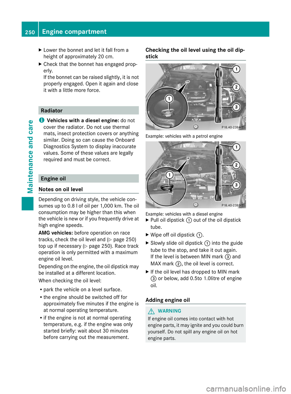
before carrying out the measurement. Checking the oil level using the oil dip-
stick
Example: vehicles with a petrol engine
Example: vehicles with a diesel engine
X
Pull oil dipstick :out of the oil dipstick
tube.
X Wipe off oil dipstick :.
X Slowly slide oil dipstick :into the guide
tube to the stop, and take it out again.
If the level is between MIN mark =and
MAX mark ;, the oil level is correct.
X If the oil level has dropped to MIN mark
= or below, add 0.5to 1.0litre of engine
oil.
Adding engine oil G
WARNING
If engine oil comes into contact with hot
engine parts, it may ignite and you could burn
yourself. Do not spill any engine oil on hot
engine parts. 250
Engine compartmentMaintenance and care
Page 271 of 321
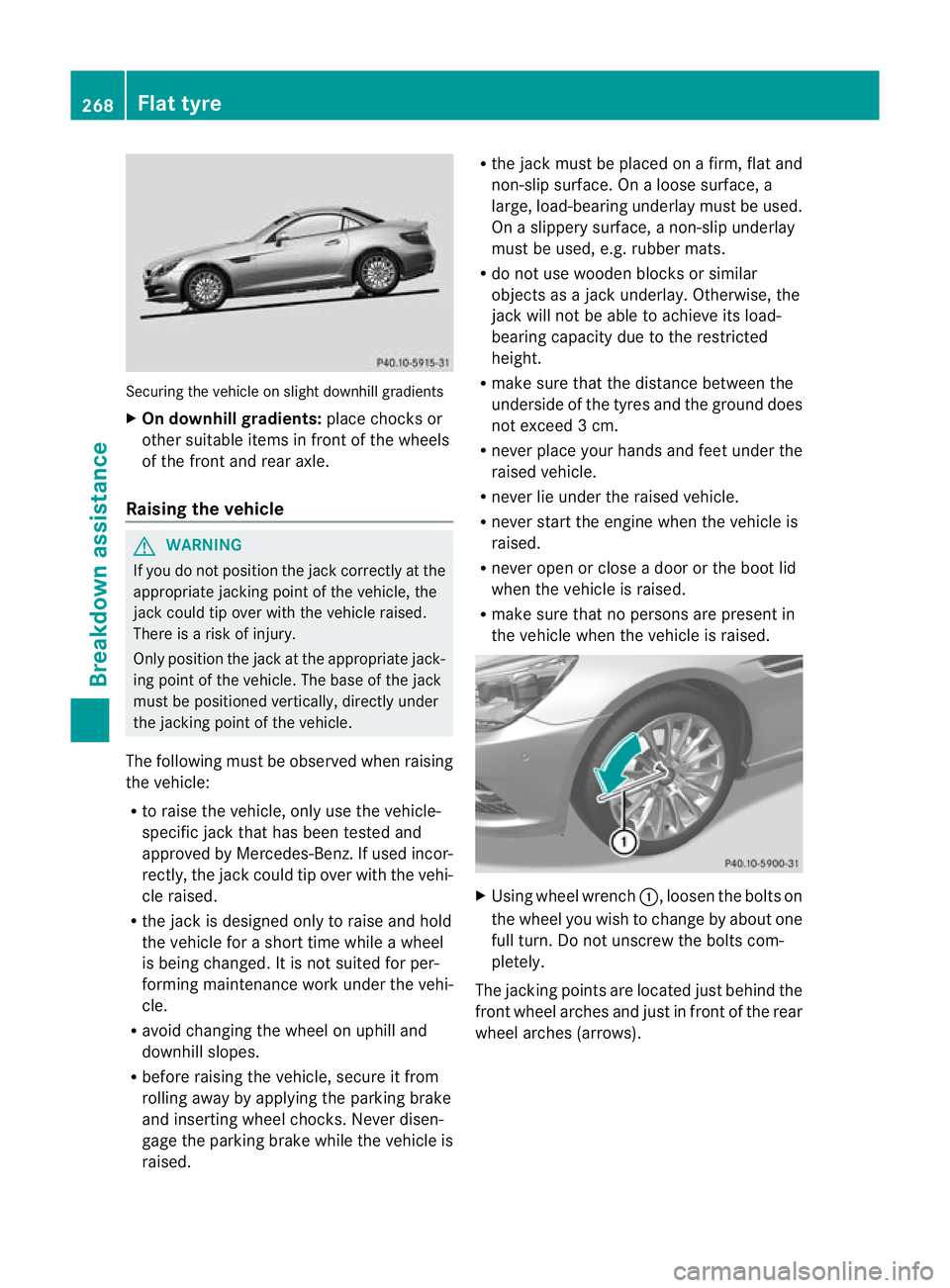
Securing the vehicle on slight downhill gradients
X
On downhill gradients: place chocks or
othe rsuitable items in fron tofthe wheels
of the front and rear axle.
Raising the vehicle G
WARNING
If you do not position the jack correctly at the
appropriate jacking point of the vehicle, the
jack could tip over with the vehicle raised.
There is a risk of injury.
Only position the jack at the appropriate jack-
ing point of the vehicle. The base of the jack
must be positioned vertically, directly under
the jacking point of the vehicle.
The following must be observed when raising
the vehicle:
R to raise the vehicle, only use the vehicle-
specific jack that has been tested and
approved by Mercedes-Benz. If used incor-
rectly, the jack could tip over with the vehi-
cle raised.
R the jack is designed only to raise and hold
the vehicle for a short time while a wheel
is being changed. It is not suited for per-
forming maintenance work under the vehi-
cle.
R avoid changing the wheel on uphill and
downhill slopes.
R before raising the vehicle, secure it from
rolling away by applying the parking brake
and inserting wheel chocks. Never disen-
gage the parking brake while the vehicle is
raised. R
the jack must be placed on a firm, flat and
non-slip surface. On a loose surface, a
large, load-bearing underlay must be used.
On a slippery surface, a non-slip underlay
must be used, e.g. rubber mats.
R do not use wooden blocks or similar
objects as a jack underlay. Otherwise, the
jack will not be able to achieve its load-
bearing capacity due to the restricted
height.
R make sure that the distance between the
underside of the tyres and the ground does
not exceed 3 cm.
R never place your hands and feet under the
raised vehicle.
R never lie under the raised vehicle.
R never start the engine when the vehicle is
raised.
R never open or close a door or the boot lid
when the vehicle is raised.
R make sure that no persons are present in
the vehicle when the vehicle is raised. X
Using wheel wrench :, loosen the bolts on
the wheel you wish to change by about one
full turn. Do not unscrew the bolts com-
pletely.
The jacking points are located just behind the
front wheel arches and just in front of the rear
wheel arches (arrows). 268
Flat tyreBreakdown assistance
Page 313 of 321
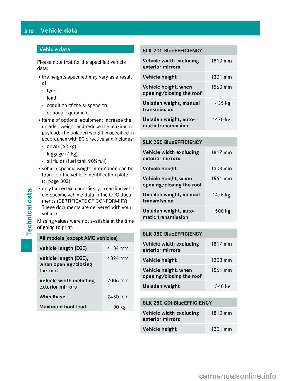
Vehicle data
Please note tha tfor the specified vehicle
data:
R the heights specified may vary as a result
of:
-tyres
- load
- condition of the suspension
- optional equipment
R items of optional equipment increase the
unladen weight and reduce the maximum
payload. The unladen weight is specified in
accordance with EC directive and includes:
-driver (68 kg)
- luggage (7 kg)
- all fluids (fuel tank 90% full)
R vehicle-specific weight information can be
found on the vehicle identification plate
(Y page 302).
R only for certain countries: you can find vehi-
cle-specific vehicle data in the COC docu-
ments (CERTIFICATE OF CONFORMITY).
These documents are delivered with your
vehicle.
Missing values were not available at the time
of going to print. All models (except AMG vehicles)
Vehicle length (ECE)
4134 mm
Vehicle length (ECE),
when opening/closing
the roof 4324 mm
Vehicle width including
exterior mirrors
2006 mm
Wheelbase
2430 mm
Maximum boot load
100 kg SLK 200 BlueEFFICIENCY
Vehicle width excluding
exterior mirrors
1810 mm
Vehicle height
1301 mm
Vehicle height, when
opening/closing the roof
1560 mm
Unladen weight, manual
transmission 1435 kg
Unladen weight, auto-
matic transmission
1470 kg
SLK 250 BlueEFFICIENCY
Vehicle width excluding
exterior mirrors
1817 mm
Vehicle height
1303 mm
Vehicle height, when
opening/closing the roof
1561 mm
Unladen weight, manual
transmission 1475 kg
Unladen weight, auto-
matic transmission
1500 kg
SLK 350 BlueEFFICIENCY
Vehicle width excluding
exterior mirrors
1817 mm
Vehicle height
1303 mm
Vehicle height, when
opening/closing the roof
1561 mm
Unladen weight
1540 kg
SLK 250 CDI BlueEFFICIENCY
Vehicle width excluding
exterior mirrors
1810 mm
Vehicle height
1301 mm310
Vehicle dataTechnical data
Page 314 of 321
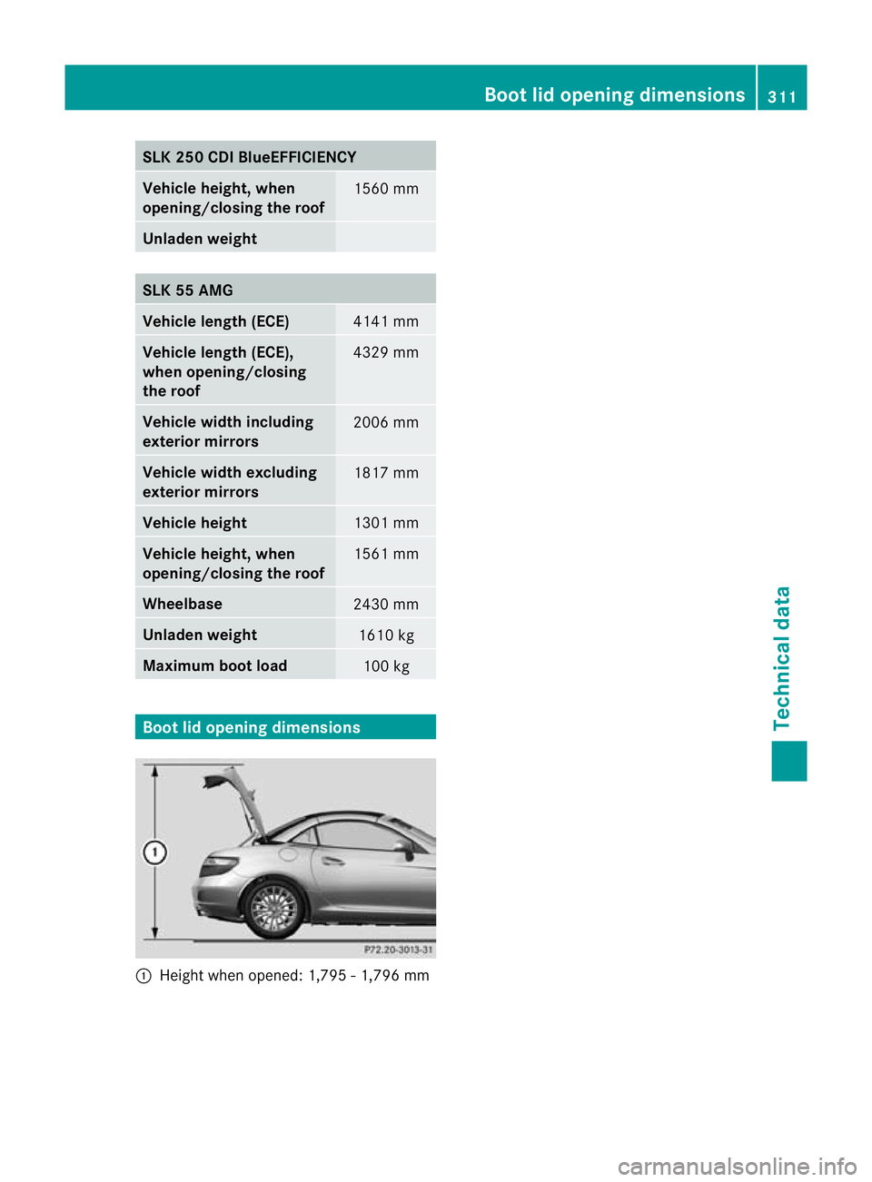
SLK 250 CDI BlueEFFICIENCY
Vehicle height, when
opening/closing the roof
1560 mm
Unladen weight
SLK 55 AMG
Vehicle length (ECE)
4141 mm
Vehicle length (ECE),
when opening/closing
the roof
4329 mm
Vehicle width including
exterior mirrors
2006 mm
Vehicle width excluding
exterior mirrors
1817 mm
Vehicle height
1301 mm
Vehicle height, when
opening/closing the roof
1561 mm
Wheelbase
2430 mm
Unladen weight
1610 kg
Maximum boot load
100 kg
Boot lid opening dimensions
:
Height when opened: 1,795 - 1,796 mm Boot lid opening dimensions
311Technical data Z