2012 MERCEDES-BENZ SLK ROADSTER radio
[x] Cancel search: radioPage 280 of 321
Jump-starting
G
WARNING
There is a risk of acid burns when jump-starting a vehicle due to the gases which escape from
the battery. Do not lean over the battery while the engine is being jump-started. G
WARNING
Gases escaping from the battery during jump-starting may cause minor explosions. Avoid cre-
ating sparks. Keep naked flames away from the battery, and do not smoke.
Comply with safety precautions when handling batteries. You will find these under "Battery (vehi-
cle)" in the index. G
WARNING
Non-combusted fuel can collect in the exhaust system and ignite. There is a risk of fire. Avoid
repeated and lengthy starting attempts.
! Avoid repeated and lengthy starting attempts. Otherwise, the catalytic converter could be
damaged by the non-combusted fuel.
Do not use a rapid charging device to start the vehicle. If your vehicle's battery is discharged,
the engine can be jump-started from another vehicle or from a second battery using jump
leads. Observe the following points:
R the battery is not accessible in all vehicles. if the other vehicle's battery is not accessible,
jump-start the vehicle using a second battery or ajump-starting device.
R you may only jump-start the vehicle when the engine and catalyti cconverter are cold.
R do not start the engine if the battery is frozen. let the battery thaw first.
R jump-starting may only be performed from batteries with a nominal voltage of 12 V.
R only use jump leads that have a sufficient cross-section and insulated terminal clamps.
R If the battery is fully discharged, leave the battery that is being used to jump-start connected
for a few minutes before attempting to start.T his charges the empty battery a little.
R Make sure that the two vehicles do not touch.
Make sure that:
R the jump leads are not damaged.
R bare parts of the terminal clamp do not come into contact with other metal parts while the
jump leads are connected to the battery.
R the jump leads cannot come into contact with parts such as the V-belt pulley or the fan.
These parts move when the engine is started and while it is running.
X Secure the vehicle by applying the electric parking brake.
X Manual transmission: engage neutral.
X Automatic transmission: move the selector lever toP.
X Switch off all electrical consumers (e.g. radio, blower, etc.).
X Open the bonnet (Y page 248). Jump-starting
277Breakdown assistance Z
Page 295 of 321
X
Make sure that the key is in posi-
tion 2(Ypage 127) in the ignition lock.
X Press the =or; button on the steer-
ing wheel to select the Serv. menu.
X Press the 9or: button to select
Tyre pressure .
X Press the abutton.
The Run Flat Indicator active Restart with OK message appears in the
multifunction display.
If you wish to confirm the restart:
X Press the abutton.
The Tyre press. now OK? message
appears in the multifunction display.
X Press the 9or: button to select
Yes .
X Press the abutton.
The Run Flat Indicator restarted message appears in the multifunction dis-
play.
After a teach-in period, the tyre pressure
loss warning system will monitor the set
tyre pressures of all four tyres.
If you wish to cancel the restart:
X Press the %button.
or
X If the Tyre press. now OK? message
appears, press the 9or: button to
select Cancel .
X Press the abutton.
The tyre pressure values stored at the last
restart will continue to be monitored. Tyre pressure monitor
Important safety notes It is the driver's responsibility to set the tyre
inflation to the recommended cold tyre pres-
sure suitable to the operating situation
(Y
page 289). Note that the correct tyre pres-
sure for the current operating situation must
first be taught-in to the tyre pressure monitor. If there is a substantial loss of pressure, the
warning threshold for the warning message is
aligned to the reference values entered.
Restart the tyre pressure monitor after
adjusting to the cold tyre pressure.
(Y page 293) The current pressures are
saved as new reference values. As a result, a
warning message will appearift he tyre pres-
sure drops significantly.
The tyre pressure monitor does not warn you
of an incorrectly set tyre pressure. Observe
the notes on the recommended tyre pressure
(Y page 289).
The tyre pressure monitor is not able to warn
you of a sudden loss of pressure, e.g. if the
tyre is penetrated by a foreign object. In the
event of a sudden loss of pressure, bring the
vehicle to a halt by braking carefully. Avoid
abrupt steering manoeuvres.
If a tyre pressure monitor system is fitted, the
vehicle's wheels have sensors fitted that
monitor the tyre pressures in all four tyres.
The tyre pressure monitor warns you if the
pressure drops in one or more of the tyres.
The tyre pressure monitor only functions if
the correct sensors are fitted to all wheels.
Information on tyre pressures is displayed in
the multifunction display. After a few minutes
of driving, the current tyre pressure of each
tyre is shown in the multifunction display.
i The tyre pressure values indicated by the
on-board computer may differ from those
measured at a filling station with a pressure
gauge. The tyre pressures shown by the on-
board computer refer to those measured at
sea level. At high altitudes, the tyre pres-
sure values indicated by a pressure gauge
are higher than those shown by the on-
board computer. In this case, do not reduce
the tyre pressures.
i The operation of the tyre pressure moni-
tor can be affected by interference from
radio transmitting equipment (e.g. radio
headphones, two-way radios) that may be
being operated in or near the vehicle. 292
Tyre pressureWheels and tyres
Page 297 of 321
the
Tyre pressures will be dis‐ played after a few minutes of driv‐
ing message.
X Press the :button.
The Use current pressures as new reference values message appears in
the multifunctio ndisplay.
If you wish to confirm the restart:
X Press the abutton.
The Tyre press. monitor restarted message appears in the multifunction dis-
play.
After you have drive
nfor a few minutes, the
system checks whether the current tyre
pressures are within the specified range.
The new tyre pressures are then accepted
as reference values and monitored.
If you wish to cancel the restart:
X Press the %button.
The tyre pressure values stored at the last
restart will continue to be monitored.
Radio type approval for the tyre pres-
sure monitor In certain countries, a radio type approval for
the tyre pressure monitor may be required.
The radio type approval number for the tyre
pressure monitor can be found online at:
http://www.mercedes-benz.de/
betriebsanleitung. Changing
awheel Flat tyre
The "Breakdown assistance" section
(Y page 263) contains information and notes
on how to deal with a fla ttyre. It also provides
instructions on changing a wheel or fitting the
spare wheel/emergency spare wheel. Interchanging the wheels
G
WARNING
Interchanging the front and rear wheels may
severely impair the drivin gcharacteristics if
the wheels or tyres have different dimensions.
The wheel brakes or suspension components
may also be damaged. There is a risk of acci-
dent.
Interchange front and rear wheels only if the
wheels and tyres are of the same dimensions.
Interchanging the front and rear wheels of
differing dimensions can render the general
operating permit invalid.
Always pay attention to the instructions and
safety notices in the section on "Wheel
changing and spare wheel fitting"
(Y page 266).
The wear patterns on the front and rear tyres
differ, depending on the operating conditions.
Interchange the wheels before a clear wear
pattern has formed on the tyres. Front tyres
typically wear more on the shoulders and the
rear tyres in the centre.
On vehicles that have the same size front and
rear wheels, you can interchange the wheels
every 5,000km to 10,000 km depending on
the degree of tyre wear. Maintain the direc-
tion of tyre rotation.
Cleant he contact surfaces of the wheel and
the brake disc thoroughly every time a wheel
is interchanged. Check the tyre pressure and,
if necessary, restart the tyre pressure loss
warning system or the tyre pressure monitor.
! On vehicles fitted with a tyre pressure
monitor, electronic components are loca-
ted in the wheel.
Tyre-fitting tools should not be applied in
the area of the valve, as this could damage
the electronic components.
Only have tyres changed at a qualified spe-
cialist workshop. 294
Changing
awheelWheels and tyres
Page 304 of 321
H
Environmental note
Daimler AG also supplies reconditioned
assemblies and parts which are of the same
quality as new parts. For these, the same war-
ranty applies as for new parts.
Always specify the vehicle identification num-
ber (VIN) (Y page 302) and the engine num-
ber (Y page 303) when ordering genuine
Mercedes-Ben zparts. Vehicle electronics
Tampering with the engine electron-
ics
G
WARNING
Always have work on the engine electronics
and related components carried out at a quali-
fied specialist workshop. Otherwise, the vehi-
cle's operating safety could be affected.
! Only have work carried out on the engine
electronics and its associated parts, such
as control units, sensors and connector
leads, at a qualified specialist workshop.
Vehicle components may otherwise wear
more quickly and the vehicle's operating
permit may be invalidated. Retrofitting of two-way radios and
mobile phones (RF transmitters)
Use the Technical Specification
ISO/TS 21609 22
implementation regulation
when retrofitting RF (radio frequency) trans-
mitters.
If your vehicle has fittings for two-way radio
equipment, use the power supply or aerial
connections intended for use with the basic
wiring. Be sure to observe the manufacturer's
additional instructions when installing. !
Have aftermarket radio frequency trans-
mitting equipmen tinstalled at a qualified
specialist workshop.
The transmission outpu tatthe aerial base
must not exceed the maximum values below. Waveband Maximum
transmission
output (PEAK) Short wave (f < 54 MHz) 30 W
4 m waveband 15 W
2 m waveband 25 W
Trunked radio/Tetra 15 W
70 cm waveband 15 W
GSM/DCS/PCS
850/900/1800/1900 10 W
UMTS/LTE 10 W
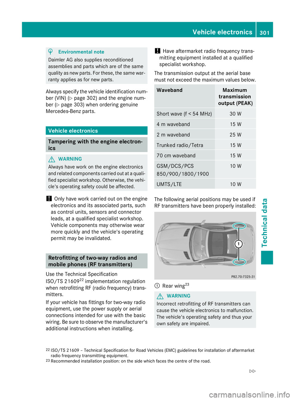
The following aerial positions may be used if
RF transmitters have been properly installed:
:
Rear wing 23 G
WARNING
Incorrect retrofitting of RF transmitters can
cause the vehicle electronicst o malfunction.
The vehicle's operating safety and thus your
own safety are impaired.
22 ISO/TS 21609 –Technical Specification for Road Vehicles (EMC) guidelines for installation of aftermarket
radio frequency transmitting equipment.
23 Recommended installation position: on the side which faces the centre of the road. Vehicle electronics
301Technical data
Z
Page 305 of 321
Have aftermarket radio frequency transmit-
ting equipment installed at a qualified spe-
cialist workshop.
G
WARNING
Incorrect retrofitting of RF transmitters can
lead to increased electromagnetic radiation in
the vehicle interior. Using an exterior aerial
takes into account current scientific discus-
sions relating to the possible health hazards
that may result from electromagnetic fields.
Have aftermarket radio frequency transmit-
ting equipment installed at a qualified spe-
cialist workshop.
Deviations with respect to aerial locations,
output and frequencies mus tbe approved by
Mercedes-Benz.
The following can be used in the vehicle with-
out restrictions:
R RF transmitters with amaximum transmis-
sion output of up to 100 mW
R mobile phones (GSM/DCS/PCS/UMTS/
LTE)
There is no restriction for aerial positions in
the outer area of the vehicle for the following
wavebands:
R Trunked radio/Tetra
R 70 cm waveband
R GSM/DCS/PCS
R UMTS/LTE
! The operating permit may be invalidated
if the instructions for installatio nand use of
RF transmitters are not observed, e.g.
approved wavebands, maximu moutput
and aerial positions on the vehicle. Identification plates
Vehicle identification plate with vehi-
cle identification number (VIN) and
paint code number
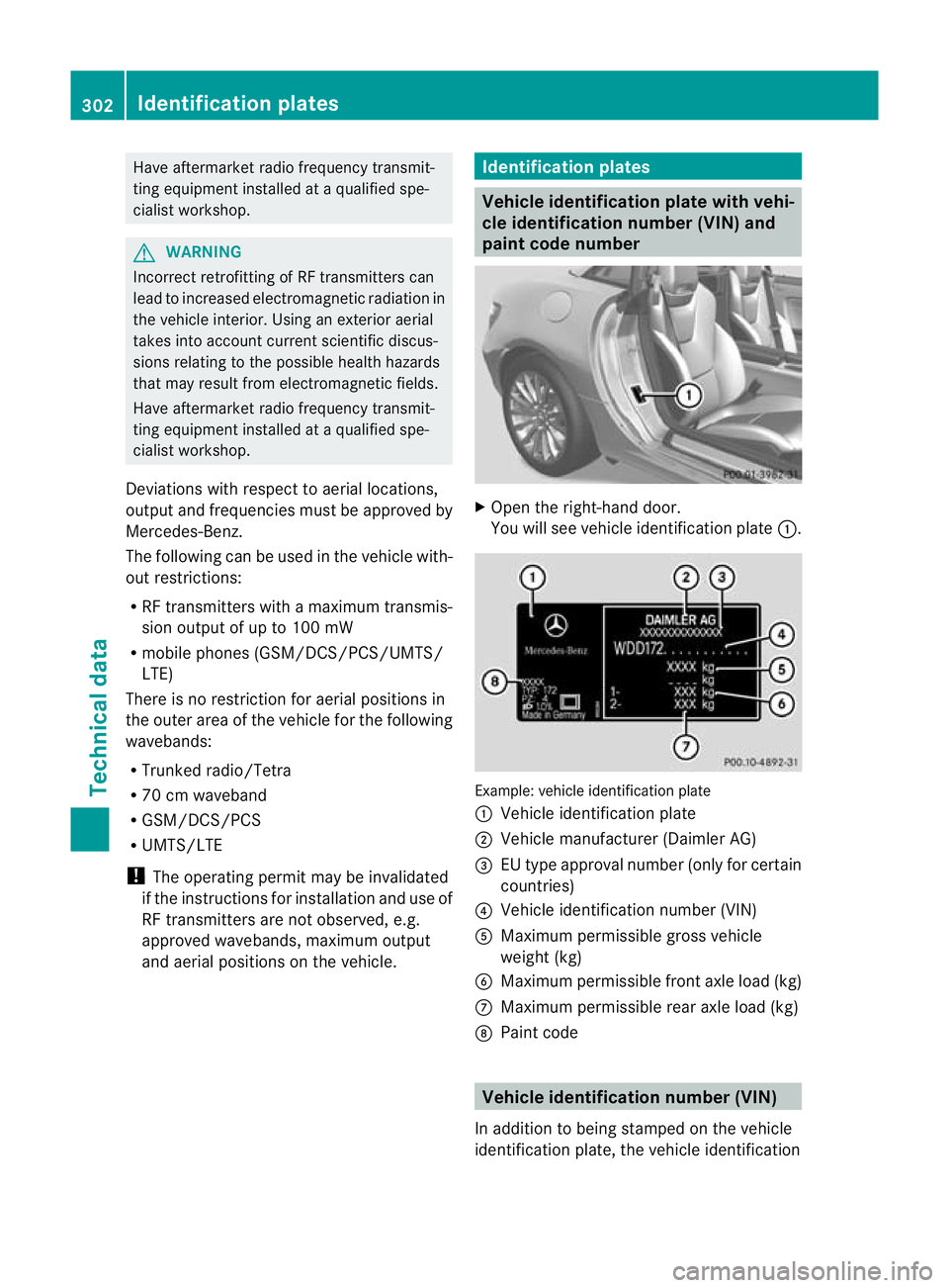
X
Open the right-hand door.
You will see vehicle identification plate :. Example: vehicle identification plate
: Vehicle identification plate
; Vehicle manufacturer (Daimle rAG)
= EU type approval number (only for certain
countries)
? Vehicle identification number (VIN)
A Maximum permissible gross vehicle
weigh t(kg)
B Maximum permissible front axle load (kg)
C Maximum permissible rea raxle load (kg)
D Paint code Vehicle identification number (VIN)
In additio nto being stamped on the vehicle
identification plate, the vehicle identification 302
Identification platesTechnical data
Page 315 of 321
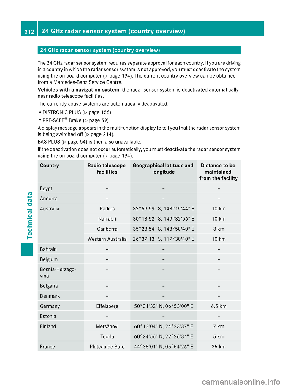
24 GHz radar sensor system (country overview)
The 24 GHz radar senso rsystem requires separat eapproval for each country. If you are driving
in a country in which the radar senso rsystem is no tapproved, you must deactivate the system
using the on-board computer (Y page 194). The current country overview can be obtained
from a Mercedes-Benz Service Centre.
Vehicles with anavigation system: the radar sensor system is deactivated automatically
near radio telescope facilities.
The currently active systems are automatically deactivated:
R DISTRONIC PLUS (Y page 156)
R PRE-SAFE ®
Brake (Y page 59)
Ad isplay message appears in the multifunction display to tell you that the radar sensor system
is being switched off (Y page 214).
BAS PLUS (Y page 54) is the nalso unavailable.
If the deactivation does not occur automatically, you must deactivate the radar sensor system
using the on-board computer (Y page 194).Country Radio telescope
facilities Geographical latitude and
longitude Distance to be
maintained
from the facility Egypt – – –
Andorra – – –
Australia Parkes 32°59'59" S, 148°15'44" E 10 km
Narrabri 30°18'52" S, 149°32'56" E 10 km
Canberra 35°23'54" S, 148°58'40" E 3 km
Western Australia 26°37'13" S, 117°30'40" E 10 km
Bahrain – – –
Belgium – – –
Bosnia-Herzego-
vina – – –
Bulgaria – – –
Denmark – – –
Germany Effelsberg 50°31'32" N, 06°53'00" E 6.5 km
Estonia – – –
Finland Metsähovi 60°13'04" N, 24°23'37" E 7 km
Tuorla 60°24'56" N, 22°26'31" E 5 km
France Plateau de Bure 44°38'01" N, 05°54'26" E 35 km312
24 GHz radar sensor system (country overview)Technical data
Page 316 of 321
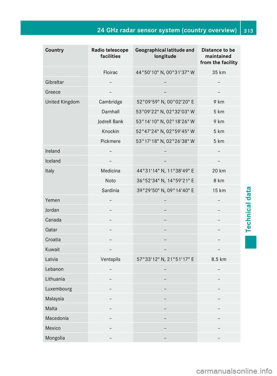
Country Radio telescope
facilities Geographica
llatitude and
longitude Distance to be
maintained
from the facility Floirac 44°50'10" N, 00°31'37" W 35 km
Gibraltar – – –
Greece – – –
United Kingdom Cambridge 52°09'59" N, 00°02'20" E 9 km
Darnhall 53°09'22" N, 02°32'03" W 5 km
Jodrell Bank 53°14'10" N, 02°18'26" W 9 km
Knockin 52°47'24" N, 02°59'45" W 5 km
Pickmere 53°17'18" N, 02°26'38" W 5 km
Ireland – – –
Iceland – – –
Italy Medicina 44°31'14" N, 11°38'49" E 20 km
Noto 36°52'34" N, 14°59'21" E 8 km
Sardinia 39°29'50" N, 09°14'40" E 15 km
Yemen – – –
Jordan – – –
Canada – – –
Qatar – – –
Croatia – – –
Kuwait – – –
Latvia Ventspils 57°33'12" N, 21°51'17" E 8.5 km
Lebanon – – –
Lithuania – – –
Luxembourg – – –
Malaysia – – –
Malta – – –
Macedonia – – –
Mexico – – –
Mongolia – – –24 GHz radar sensor system (country overview)
313Technical data Z
Page 317 of 321
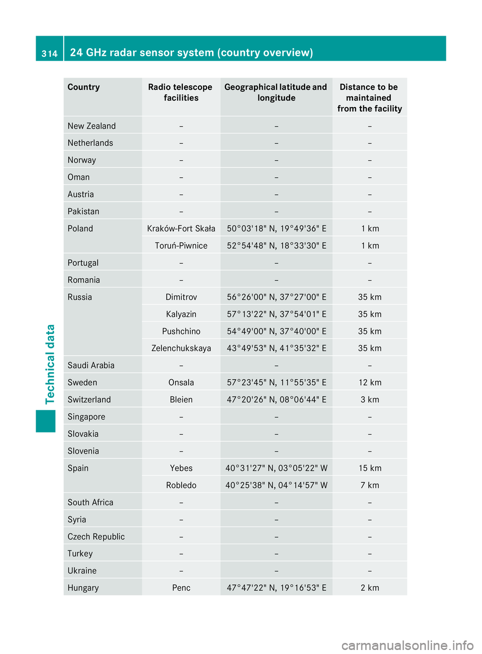
Country Radio telescope
facilities Geographica
llatitude and
longitude Distance to be
maintained
from the facility New Zealand – – –
Netherlands – – –
Norway – – –
Oman – – –
Austria – – –
Pakistan – – –
Poland Kraków-Fort Skała 50°03'18" N, 19°49'36" E 1 km
Toruń-Piwnice 52°54'48" N, 18°33'30" E 1 km
Portugal – – –
Romania – – –
Russia Dimitrov 56°26'00" N, 37°27'00" E 35 km
Kalyazin 57°13'22" N, 37°54'01" E 35 km
Pushchino 54°49'00" N, 37°40'00" E 35 km
Zelenchukskaya 43°49'53" N, 41°35'32" E 35 km
Saudi Arabia – – –
Sweden Onsala 57°23'45" N, 11°55'35" E 12 km
Switzerland Bleien 47°20'26" N, 08°06'44" E 3 km
Singapore – – –
Slovakia – – –
Slovenia – – –
Spain Yebes 40°31'27" N, 03°05'22" W 15 km
Robledo 40°25'38" N, 04°14'57" W 7 km
South Africa – – –
Syria – – –
Czech Republic – – –
Turkey – – –
Ukraine – – –
Hungary Penc 47°47'22" N, 19°16'53" E 2 km314
24 GHz radar sensor system (country overview)Technical data