2012 MERCEDES-BENZ SL ROADSTER key battery
[x] Cancel search: key batteryPage 162 of 637
General notes
:
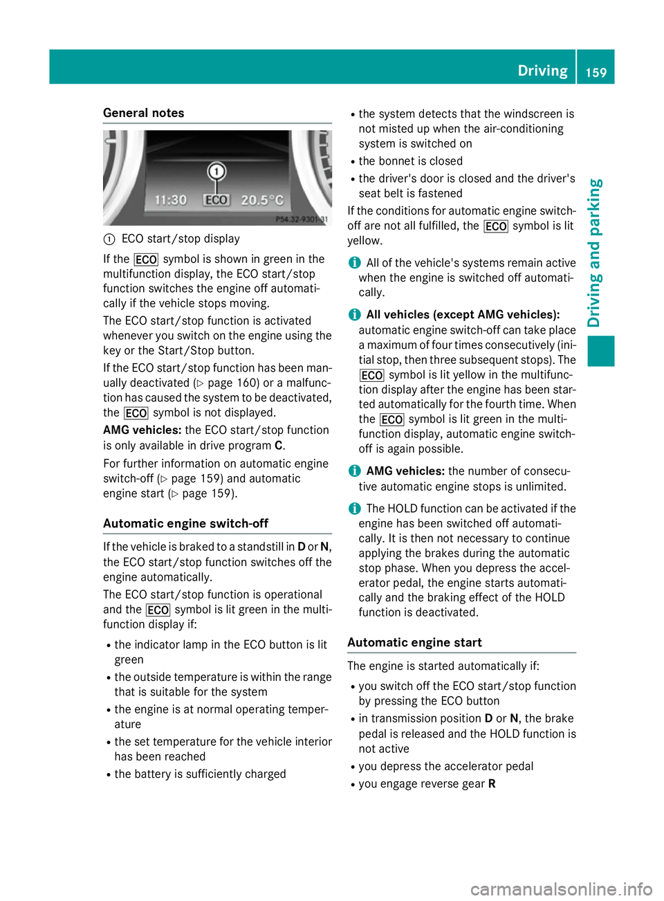
ECO start/stop display
If the ¤ symbol is shown in green in the
multifunction display, the ECO start/stop
function switches the engine off automati-
cally if the vehicle stops moving.
The ECO start/stop function is activated
whenever you switch on the engine using the
key or the Start/Stop button.
If the ECO start/stop function has been man- ually deactivated (Y page 160) or a malfunc-
tion has caused the system to be deactivated, the ¤ symbol is not displayed.
AMG vehicles: the ECO start/stop function
is only available in drive program C.
For further information on automatic engine
switch-off (Y page 159) and automatic
engine start (Y page 159).
Automatic engine switch-off If the vehicle is braked to a standstill in
Dor N,
the ECO start/stop function switches off the engine automatically.
The ECO start/stop function is operational
and the ¤symbol is lit green in the multi-
function display if:
R the indicator lamp in the ECO button is lit
green
R the outside temperature is within the range
that is suitable for the system
R the engine is at normal operating temper-
ature
R the set temperature for the vehicle interior
has been reached
R the battery is sufficiently charged R
the system detects that the windscreen is
not misted up when the air-conditioning
system is switched on
R the bonnet is closed
R the driver's door is closed and the driver's
seat belt is fastened
If the conditions for automatic engine switch- off are not all fulfilled, the ¤symbol is lit
yellow.
i All of the vehicle's systems remain active
when the engine is switched off automati-
cally.
i All vehicles (except AMG vehicles):
automatic engine switch-off can take place a maximum of four times consecutively (ini-
tial stop, then three subsequent stops). The
¤ symbol is lit yellow in the multifunc-
tion display after the engine has been star- ted automatically for the fourth time. Whenthe ¤ symbol is lit green in the multi-
function display, automatic engine switch-
off is again possible.
i AMG vehicles:
the number of consecu-
tive automatic engine stops is unlimited.
i The HOLD function can be activated if the
engine has been switched off automati-
cally. It is then not necessary to continue
applying the brakes during the automatic
stop phase. When you depress the accel-
erator pedal, the engine starts automati-
cally and the braking effect of the HOLD
function is deactivated.
Automatic engine start The engine is started automatically if:
R
you switch off the ECO start/stop function
by pressing the ECO button
R in transmission position Dor N, the brake
pedal is released and the HOLD function is not active
R you depress the accelerator pedal
R you engage reverse gear R Driving
159Driving and parking Z
Page 165 of 637
Problems with the engine
Problem
Possible causes/consequences and
M
MSolutions The engine does not
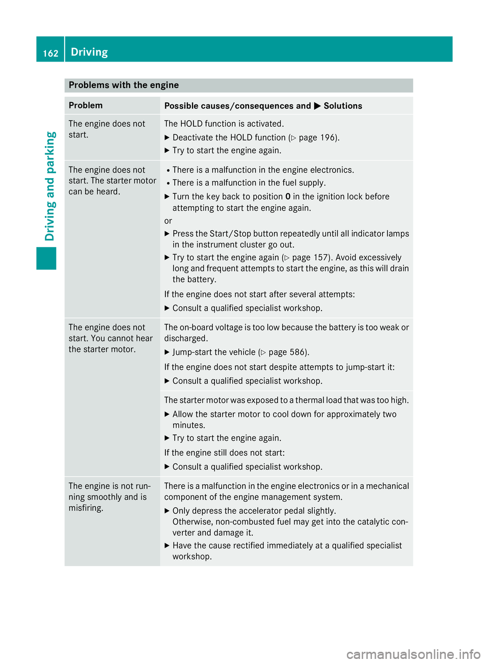
start. The HOLD function is activated.
X Deactivate the HOLD function (Y page 196).
X Try to start the engine again. The engine does not
start. The starter motor
can be heard. R
There is a malfunction in the engine electronics.
R There is a malfunction in the fuel supply.
X Turn the key back to position 0in the ignition lock before
attempting to start the engine again.
or X Press the Start/Stop button repeatedly until all indicator lamps
in the instrument cluster go out.
X Try to start the engine again (Y page 157). Avoid excessively
long and frequent attempts to start the engine, as this will drain
the battery.
If the engine does not start after several attempts: X Consult a qualified specialist workshop. The engine does not
start. You cannot hear
the starter motor. The on-board voltage is too low because the battery is too weak or
discharged.
X Jump-start the vehicle (Y page 586).
If the engine does not start despite attempts to jump-start it:
X Consult a qualified specialist workshop. The starter motor was exposed to a thermal load that was too high.
X Allow the starter motor to cool down for approximately two
minutes.
X Try to start the engine again.
If the engine still does not start:
X Consult a qualified specialist workshop. The engine is not run-
ning smoothly and is
misfiring. There is a malfunction in the engine electronics or in a mechanical
component of the engine management system.
X Only depress the accelerator pedal slightly.
Otherwise, non-combusted fuel may get into the catalytic con-
verter and damage it.
X Have the cause rectified immediately at a qualified specialist
workshop. 162
DrivingDriving and parking
Page 256 of 637
Display messages
Possible causes/consequences and
M
MSolutions !
Parking Parking
brake
brakeinop‐
inop‐
erative
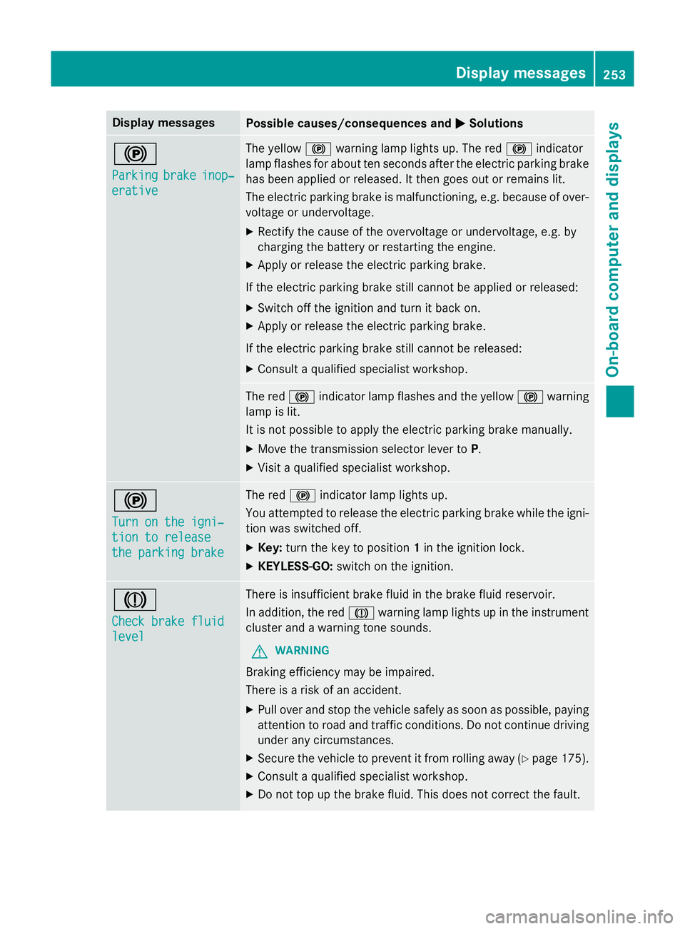
erative The yellow
!warning lamp lights up. The red !indicator
lamp flashes for about ten seconds after the electric parking brake
has been applied or released. It then goes out or remains lit.
The electric parking brake is malfunctioning, e.g. because of over- voltage or undervoltage.
X Rectify the cause of the overvoltage or undervoltage, e.g. by
charging the battery or restarting the engine.
X Apply or release the electric parking brake.
If the electric parking brake still cannot be applied or released: X Switch off the ignition and turn it back on.
X Apply or release the electric parking brake.
If the electric parking brake still cannot be released: X Consult a qualified specialist workshop. The red
!indicator lamp flashes and the yellow !warning
lamp is lit.
It is not possible to apply the electric parking brake manually.
X Move the transmission selector lever to P.
X Visit a qualified specialist workshop. !
Turn on the igni‐ Turn on the igni‐
tion to release tion to release
the parking brake the parking brake The red
!indicator lamp lights up.
You attempted to release the electric parking brake while the igni-
tion was switched off.
X Key: turn the key to position 1in the ignition lock.
X KEYLESS-GO: switch on the ignition. J
Check brake fluid Check brake fluid
level level There is insufficient brake fluid in the brake fluid reservoir.
In addition, the red Jwarning lamp lights up in the instrument
cluster and a warning tone sounds.
G WARNING
Braking efficiency may be impaired.
There is a risk of an accident. X Pull over and stop the vehicle safely as soon as possible, paying
attention to road and traffic conditions. Do not continue driving
under any circumstances.
X Secure the vehicle to prevent it from rolling away (Y page 175).
X Consult a qualified specialist workshop.
X Do not top up the brake fluid. This does not correct the fault. Display
messages
253On-board computer and displays Z
Page 523 of 637
Rear-compartment screens
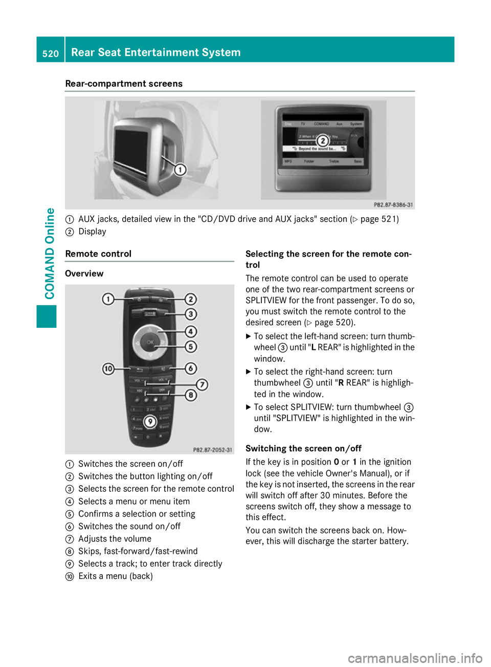
:
AUX jacks, detailed view in the "CD/DVD drive and AUX jacks" section (Y page 521)
; Display
Remote control Overview
:
Switches the screen on/off
; Switches the button lighting on/off
= Selects the screen for the remote control
? Selects a menu or menu item
A Confirms a selection or setting
B Switches the sound on/off
C Adjusts the volume
D Skips, fast-forward/fast-rewind
E Selects a track; to enter track directly
F Exits a menu (back) Selecting the screen for the remote con-
trol
The remote control can be used to operate
one of the two rear-compartment screens or
SPLITVIEW for the front passenger. To do so,
you must switch the remote control to the
desired screen (Y page 520).
X To select the left-hand screen: turn thumb-
wheel =until "L REAR" is highlighted in the
window.
X To select the right-hand screen: turn
thumbwheel =until "R REAR" is highligh-
ted in the window.
X To select SPLITVIEW: turn thumbwheel =
until "SPLITVIEW" is highlighted in the win-
dow.
Switching the screen on/off
If the key is in position 0or 1in the ignition
lock (see the vehicle Owner's Manual), or if
the key is not inserted, the screens in the rear
will switch off after 30 minutes. Before the
screens switch off, they show a message to
this effect.
You can switch the screens back on. How-
ever, this will discharge the starter battery. 520
Rear Seat Entertainment SystemCOMAND Online
Page 553 of 637
X
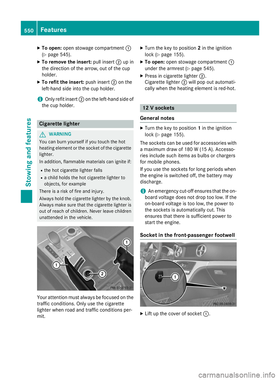
To open: open stowage compartment :
(Y page 545).
X To remove the insert: pull insert;up in
the direction of the arrow, out of the cup
holder.
X To refit the insert: push insert;on the
left-hand side into the cup holder.
i Only refit insert
;on the left-hand side of
the cup holder. Cigarette lighter
G
WARNING
You can burn yourself if you touch the hot
heating element or the socket of the cigarette lighter.
In addition, flammable materials can ignite if:
R the hot cigarette lighter falls
R a child holds the hot cigarette lighter to
objects, for example
There is a risk of fire and injury.
Always hold the cigarette lighter by the knob.
Always make sure that the cigarette lighter is
out of reach of children. Never leave children unattended in the vehicle. Your attention must always be focused on the
traffic conditions. Only use the cigarette
lighter when road and traffic conditions per-
mit. X
Turn the key to position 2in the ignition
lock (Y page 155).
X To open: open stowage compartment :
under the armrest (Y page 545).
X Press in cigarette lighter ;.
Cigarette lighter ;will pop out automati-
cally when the heating element is red-hot. 12 V sockets
General notes X
Turn the key to position 1in the ignition
lock (Y page 155).
The sockets can be used for accessories with a maximum draw of 180 W(15 A). Accesso-
ries include such items as bulbs or chargers
for mobile phones.
If you use the sockets for long periods when
the engine is switched off, the battery may
discharge.
i An emergency cut-off ensures that the on-
board voltage does not drop too low. If the
on-board voltage is too low, the power to
the sockets is automatically cut. This
ensures that there is sufficient power to
start the engine.
Socket in the front-passenger footwell X
Lift up the cover of socket :.550
FeaturesStowing and fea
tures
Page 555 of 637
More information on suitable mobile phones,
mobile phone brackets and on connecting
Bluetooth ®
-capable mobile phones with
COMAND Online can be obtained:
R at your Mercedes-Benz Service Centre
R on the Internet at http://www.mercedes-
benz.com/connect
i The functions and services available when
you use the phone depend on your mobile
phone model and service provider.
Using a mobile phone If the mobile phone is inserted in the mobile
phone bracket, the mobile phone will be
charged and connected with the exterior aer-
ial.
X Open the telephone compartment
(Y page 545).
X Place the mobile phone bracket into the
pre-installed fitting; see the separate instal-
lation instructions for the mobile phone fit-
ting.
X Insert the mobile phone into the mobile
phone bracket; see the separate installa-
tion instructions for the mobile phone fit-
ting.
Operating the mobile phone You can operate the telephone using the
6 and~ buttons on the multifunction
steering wheel. You can operate other mobile
phone functions via the on-board computer
(Y page 235).
When you remove the key from the ignition
lock, the mobile phone is disconnected from
the hands-free system. Active calls will first
be transferred to the mobile phone directly. Charge maintenance socket
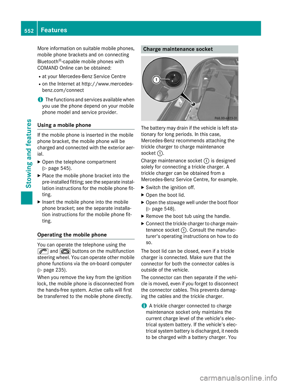
The battery may drain if the vehicle is left sta-
tionary for long periods. In this case,
Mercedes-Benz recommends attaching the
trickle charger to charge maintenance
socket :.
Charge maintenance socket :is designed
solely for connecting a trickle charger. A
trickle charger can be obtained from a
Mercedes-Benz Service Centre, for example.
X Switch the ignition off.
X Open the boot lid.
X Open the stowage well under the boot floor
(Y page 548).
X Remove the boot tub using the handle.
X Connect the trickle charger to charge main-
tenance socket :. Consult the manufac-
turer's operating instructions on how to do
so.
The boot lid can be closed, even if a trickle
charger is connected. Make sure that the
connector for both the connector cables is
outside of the vehicle.
The connector can then separate if the vehi-
cle is moved, even if you forget to disconnect
the connector cables. This prevents damag-
ing the cables and the trickle charger.
i A trickle charger connected to charge
maintenance socket only maintains the
current charge level of the vehicle's elec-
trical system battery. If the vehicle's elec-
trical system battery is discharged, it needs
to be charged with a battery charger. You 552
FeaturesStowing and features
Page 556 of 637
will find further information on charging the
battery on (Y page 582). Garage door opener
General notes The HomeLink
®
garage door opener integra-
ted in the rear-view mirror allows you to oper- ate up to three different door and gate sys-
tems.
Once programmed, the integrated garage
door opener in the rear-view mirror will
assume the function of the garage door sys-
tem's remote control. Please also read the
operating instructions for the garage door
system.
When programming a garage door opener,
park the vehicle outside the garage. Do not
run the engine while programming.
The garage door opener is only available for
certain countries. Observe the legal require-
ments for each individual country.
The HomeLink ®
garage door opener is com-
patible with most European garage and gate
opener drives. More information on Home-
Link ®
and/or compatible products is availa-
ble:
R at a qualified specialised workshop
R via the HomeLink ®
Hotline
(0) 08000 466 354 65 or alternatively
+49 (0) 6838 907-277
R on the Internet at
http://www.homelink.com
Important safety notes G
WARNING
When you operate or program the garage door with the integrated garage door opener, per-
sons in the range of movement of the garage
door can become trapped or struck by the
garage door. There is a risk of injury.
When using the integrated garage door
opener, always make sure that nobody is within the range of movement of the garage
door.
G
WARNING
Combustion engines emit poisonous exhaust
gases such as carbon monoxide. Inhaling
these exhaust gases leads to poisoning. There is a risk of fatal injury. Therefore never leave
the engine running in enclosed spaces with-
out sufficient ventilation.
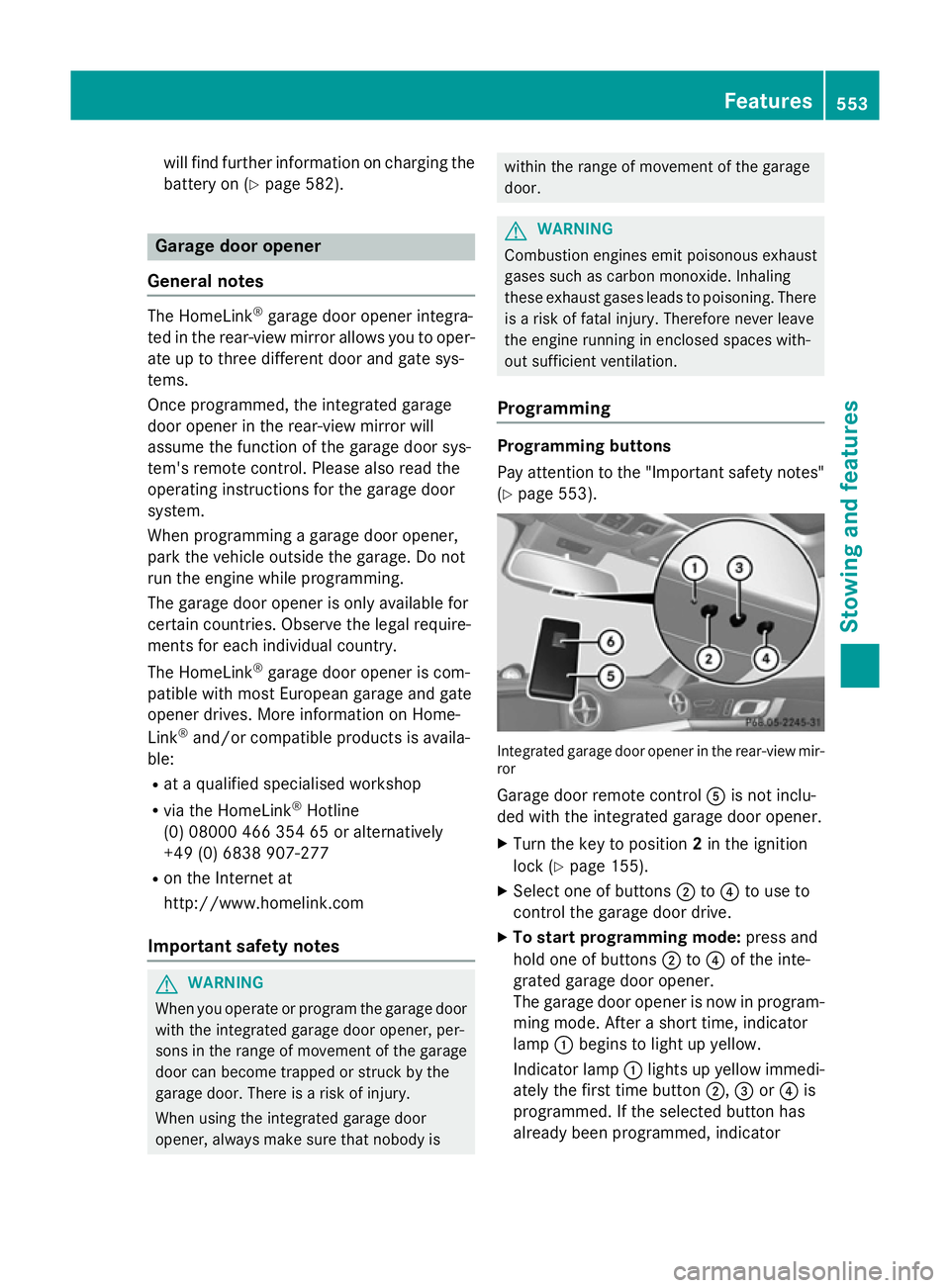
Programming Programming buttons
Pay attention to the "Important safety notes"
(Y page 553). Integrated garage door opener in the rear-view mir-
ror
Garage door remote control Ais not inclu-
ded with the integrated garage door opener.
X Turn the key to position 2in the ignition
lock (Y page 155).
X Select one of buttons ;to? to use to
control the garage door drive.
X To start programming mode: press and
hold one of buttons ;to? of the inte-
grated garage door opener.
The garage door opener is now in program-
ming mode. After a short time, indicator
lamp :begins to light up yellow.
Indicator lamp :lights up yellow immedi-
ately the first time button ;,=or? is
programmed. If the selected button has
already been programmed, indicator Features
553Stowing and features Z
Page 572 of 637
vehicle in a tow-through car wash. Other
transmission positions may lead to damage to the vehicle.
! Make sure that:
R the side windows and the roof are com-
pletely closed
R the climate control blower is switched off
R the windscreen wiper switch is at posi-
tion 0
The vehicle could otherwise be damaged.
You can wash the vehicle in an automatic car
wash from the very start.
Wash off excess dirt before cleaning the vehi- cle in an automatic car wash.
After using an automatic car wash, wipe wax
off the windscreen and the wiper blades. This
will prevent smears and reduce wiping noises caused by residue on the windscreen.
Washing by hand In some countries, washing by hand is only
allowed at specially equipped washing bays.
Observe the legal requirements for each indi- vidual country.
X Do not use hot water and do not wash the
vehicle in direct sunlight.
X Use a soft sponge to clean.
X Use a mild cleaning agent, such as a car
shampoo approved by Mercedes-Benz.
X Thoroughly hose down the vehicle with a
gentle jet of water.
X Do not point the water jet directly towards
the air inlet.
X Use plenty of water and rinse out the
sponge frequently.
X Rinse the vehicle with clean water and dry
thoroughly with a chamois.
X Do not let the cleaning agent dry on the
paintwork.
When using the vehicle in winter, remove all
traces of road salt deposits carefully and as
soon as possible. High-pressure cleaning equipment G
WARNING
The water jet of circular-jet nozzles (dirt grind- ers) can cause damage not visible from the
outside to tyres or chassis components. Com-
ponents damaged in this way can unexpect-
edly fail. There is a risk of an accident.
Do not use high-pressure cleaners with circu-
lar-jet nozzles to clean the vehicle. Have dam- aged tyres or chassis components replaced
immediately.
! Always maintain a distance of at least
30 cm between the vehicle and the high-
pressure cleaner nozzle. Information about
the correct distance is available from the
equipment manufacturer.
Move the high-pressure cleaner nozzle
around when cleaning your vehicle.
Do not aim directly at any of the following:
R tyres
R door gaps, roof gaps, joints etc.
R electrical components
R battery
R connectors
R lights
R seals
R trim elements
R ventilation slots
Damaged seals or electrical components
can lead to leaks or failures.
! Vehicles with HANDS-FREE ACCESS: if a
key with KEYLESS-GO is within the detec-
tion range of the KEYLESS-GO antenna, the
following situations could lead to the unin-
tentional opening of the boot lid:
R using a car wash
R using a high-pressure cleaner
Make sure that the key is at least 2 m away
from the vehicle. Care
569Maintenance and care Z