2012 MERCEDES-BENZ GLK SUV change time
[x] Cancel search: change timePage 220 of 381
The maximum noseweight of the trailer draw-
bar on the ball coupling is 80 kg. However,
the actual noseweight may not be higher than
the value which is given on the trailer tow
hitch or trailer identification plates. The low-
est weight applies.
! Use a drawbar noseweight as close as
possible to the maximum permissible nose-
weight. Do not use a noseweight of less
than 50kg, otherwise the trailer may come
loose.
Note that the payload and the rear axle load
are reduced by the actual payload.
i The height of the ball coupling changes
with the load of the vehicle. If necessary,
use a trailer with a height-adjustable draw-
bar.
Driving tips i
Observe the notes on ESP ®
trailer stabi-
lisation (Y page 69).
The maximum permissible speed for vehicle/
trailer combinations depends on the type of
trailer. Before beginning the journey, check
the trailer's documents to see what the max-
imum permitted speed is. Observe the legally
prescribed maximum speed in the relevant
country.
For certain Mercedes-Benz vehicles, the max-
imum permissible rear axle load is increased
when towing a trailer. Refer to the "Technical
data" section to find out whether this applies
to your vehicle. If you utilise any of the added
maximum rear axle load when towing a trailer,
the vehicle/trailer combination may not
exceed a maximum speed of 100 km/h for
reasons concerning the operating permit.
This also applies in countries in which the
permissible maximum speed for vehicle/
trailer combinations is above 100 km/h.
When towing a trailer, your vehicle's handling
characteristics will be different in comparison
to when driving without a trailer, and it will
consume more fuel. Change into a lower gear in good time on long
and steep downhill gradients. On vehicles
with automatic transmission, you have to
select shift range
1,2or 3.
i This also applies if you have activated
cruise control or SPEEDTRONIC.
This will use the braking effect of the engine,
so less braking will be required to prevent the
vehicle from gaining speed. This relieves the
load on the brake system and prevents the
brakes from overheating and wearing too
quickly. If you need additional braking,
depress the brake pedal repeatedly rather
than continuously.
Driving tips R
Maintain a greater distance from the vehi-
cle in front than when driving without a
trailer.
R Avoid braking abruptly. If possible, brake
gently at first to allow the trailer to run on.
Then, increase the braking force rapidly.
R The values given for gradient-climbing
capabilities from a standstill refer to sea
level. When driving in mountainous areas,
note that the power output of the engine,
and consequently the vehicle's gradient-
climbing capability, decrease with increas-
ing altitude.
If the trailer swings from side to side:
X Do not accelerate.
X Do not countersteer.
X Brake if necessary. Fitting the ball coupling
X Make a note of the ball coupling key num-
ber.
i You can use this number to obtain a
replacement key from a Mercedes-Benz
Service Centre. Towing a trailer
217Driving and parking Z
Page 230 of 381
The approximate range which can be covered
depends on the fuel level and your current
driving style. If there is only a small amount
of fuel left in the fuel tank, the display shows
a vehicle being refuelled Cinstead of the
range. Switching the daytime driving lights
on/off
If you have activated the Day. driv.
Day. driv.
lights: lights: function and the light switch is in the
à position, the daytime driving lights are
switched on automatically when the engine is
running. When it is dark, the side lamps and
the dipped-beam headlamps are switched on
automatically.
On vehicles with daytime driving lamps, the
factory setting is on
on.
If you want to change the setting for the Day. Day.
driv. lights:
driv. lights: function, you have to turn
the key in the ignition lock to position 1.
X Press the Vbutton on the steering
wheel repeatedly until the Day. driv.
Day. driv.
lights:
lights: menu appears.
You will see the selected setting: on
onor
off
off.
X Press the WorX button to change
the setting. Time/date
i Depending on your vehicle's equipment,
the time can be set using the on-board
computer or the audio system/COMAND,
see the separate operating instructions.
X Press the Vbutton on the steering
wheel repeatedly until the "Time/date"
menu appears.
X To set: use the Cbutton to select the
display you want to change: hour, minutes,
day, month, year. X
Press WorX to set the selected dis-
play.
X To save: press the Cbutton.
The next display is selected. Displays and operation (12-button
multifunction steering wheel)
Coolant temperature gauge
The coolant temperature gauge is in the
instrument cluster on the left-hand side.
Under normal operating conditions and with
the specified coolant level, the coolant tem-
perature may rise to 120 †.
At high outside temperatures and when driv-
ing uphill, the coolant temperature may rise
to the end of the scale. Rev counter
The red band in the rev counter indicates the
engine's overrevving range.
! Do not drive in the overrevving range.
Doing so will damage the engine.
The fuel supply is interrupted to protect the
engine when the red band is reached. Outside temperature display
The outside temperature display is in the mul-
tifunction display (Y page 229). G
WARNING
At temperatures just above freezing point, the
street may be icy, especially in wooded areas
or on bridges. If you do not adapt your driving
style to the conditions, the vehicle could skid.
For this reason, adapt your driving style and
speed to the weather conditions.
Changes in the outside temperature are dis-
played after a short delay. Displays and operation (12-button multifunction steering wheel)
227On-board computer and displays Z
Page 245 of 381
Activating/deactivating the acoustic
locking confirmation
If you switch on the Acoustic
Acoustic Lock Lockfunction,
an acoustic signal sounds when you lock the
vehicle.
X Press the =or; button on the steer-
ing wheel to select the Settings Settingsmenu.
X Press the :or9 button to select the
Vehicle
Vehicle submenu.
X Press ato confirm.
X Press the :or9 button to select the
Acoustic Lock
Acoustic Lock function.
If the Acoustic
Acoustic Lock
Lockfunction is activated,
the & symbol in the multifunction dis-
play lights up red.
X Press the abutton to save the setting.
Activating/deactivating the radar sensor
system
X Press the =or; button on the steer-
ing wheel to select the Settings
Settings menu.
X Press the :or9 button to select the
Vehicle Vehicle submenu.
X Press ato confirm.
X Press the 9or: button to select
Radar sensor (See Owner's Man.):
Radar sensor (See Owner's Man.): .
You will see the selected setting: Activa‐
Activa‐
ted
ted orDeactivated
Deactivated .
X Press the abutton to save the setting.
i You must deactivate the radar sensor sys-
tem in certain countries and near radio
telescope facilities. For further informa-
tion, see (Y page 375).
When you are close to radio telescope facili-
ties, the radar sensor system will be deacti-
vated automatically.
The following systems are switched off when
the radar sensor system is deactivated:
R DISTRONIC PLUS (Y page 178)
R BAS PLUS (Y page 66)
R PRE-SAFE ®
Brake (Y page 69)
R Active Blind Spot Assist (Y page 207)Heating Auxiliary heating departure time
Only vehicles with auxiliary heating
(Y
page 137) have this function.
In the Heating Heating submenu, you can select a
stored departure time or change a departure
time.
The auxiliary heating timer function calcu-
lates the switch-on time according to the out-
side temperature so that the vehicle is pre-
heated by the departure time. When the
departure time is reached, the auxiliary heat-
ing continues to heat for a further five
minutes and then switches off. The auxiliary
heating adopts the THERMATIC or
THERMOTRONIC temperature setting.
You can switch off the auxiliary heating by
using the remote control or the auxiliary heat-
ing button on the centre console. G
WARNING
Exhaust fumes are produced when the auxili-
ary heating is in operation. Inhaling these
exhaust fumes can be poisonous. You should
therefore switch off the auxiliary heating in
confined spaces without an extraction sys-
tem, e.g. a garage. G
WARNING
When operating the auxiliary heating parts of
the vehicle can get very hot. Make sure that
the exhaust system does not under any cir-
cumstances come into contact with easily
ignitable material such as dry grass or fuels.
The material could otherwise ignite and set
the vehicle alight. Choose your parking spot
accordingly.
Operating the auxiliary heating is thus pro-
hibited at filling stations or when your vehicle
is being refuelled. You must therefore switch
off the auxiliary heating at filling stations.
! Operating the auxiliary heating/ventila-
tion draws on the vehicle battery. After you
have heated or ventilated the vehicle a 242
Displays and operation (12-button multifunction steering wheel)On-board computer and displays
Page 246 of 381
maximum of two times, drive for a longer
distance.
i Switch the auxiliary heating on regularly
once a month for about ten minutes.
Selecting the departure time or deactivat-
ing a selected departure time
X Press the =or; button on the steer-
ing wheel to select the Settings Settingsmenu.
X Press the :or9 button to select the
Heating
Heating submenu.
X Press ato confirm.
You will see the selected setting.
X Press ato confirm.
X Press the :or9 button to select
one of the three departure times or Timer
Timer
off
off (no timer active).
X Press ato confirm.
If a departure time is selected, the yellow
indicator lamp lights up on the auxiliary
heating button.
Changing the departure time
X Press the =or; button on the steer-
ing wheel to select the Settings
Settings menu.
X Press the :or9 button to select the
Heating
Heating submenu.
X Press ato confirm.
You will see the selected setting.
X Press ato confirm.
X Press the :or9 button to select A
A,
B B or Change C
Change C.
X Press ato confirm.
You can now change the departure time.
X Press the =or; button to select the
display to be changed: hours, minutes.
X Press the :or9 button to set the
selected display.
X Press the abutton to store the entry.
The yellow indicator lamp on the auxiliary
heating button lights up. Convenience Activating/deactivating the EASY-
ENTRY/EXIT feature
G
WARNING
The steering wheel moves when the EASY-
ENTRY/EXIT feature is active. There is a risk
of occupants becoming trapped. Before acti-
vating the EASY-ENTRY/EXIT feature, make
sure that nobody can become trapped.
Do not leave children unsupervised in the
vehicle, even if they are secured in a child
restraint system. The children could open the
driver's door and thereby unintentionally acti-
vate the EASY-ENTRY/EXIT feature and
become trapped.
X Press the =or; button on the steer-
ing wheel to select the Settings Settingsmenu.
X Press the :or9 button to select the
CONVENIENCE
CONVENIENCE submenu.
X Press ato confirm.
X Press the :or9 button to select the
Easy Entry/Exit:
Easy Entry/Exit: function.
If the Easy Entry/Exit
Easy Entry/Exit function is activa-
ted, the vehicle steering wheel is displayed
in red in the multifunction display.
X Press the abutton to save the setting.
Further information on the EASY-ENTRY/EXIT
feature (Y page 102).
Switching the belt adjustment on/off
X Press the =or; button on the steer-
ing wheel to select the Settings Settingsmenu.
X Press the :or9 button to select the
Convenience
Convenience submenu.
X Press ato confirm.
X Press the :or9 button to select the
Belt adjustment
Belt adjustment function.
When the Belt adjustment
Belt adjustment function is
activated, the vehicle seat belt is displayed
in red in the multifunction display.
X Press the abutton to save the setting.
For further information on belt adjustment,
see (Y page 51). Displays and operation (12-button multifunction steering wheel)
243On-board computer and displays Z
Page 299 of 381
Useful information
i This Owner's Manual describes all mod-
els, series and optional equipment for your
vehicle that were available at the time of
going to press. National variations are pos-
sible. Note that your vehicle may not be
equipped with all of the functions descri-
bed. This is also the case for systems and
functions relevant to safety.
i Read the information on qualified special-
ist workshops: (Y page 27). Loading guidelines
G
WARNING
Secure and position the load as described in
the loading guidelines.
Otherwise, vehicle occupants could
be injured by the load being thrown around in
the event of sharp braking, a sudden change
in direction or an accident.
You will find further information in the "Secur-
ing a load" section.
Even if you follow all the loading guidelines,
the load will increase the risk of injury in the
event of an accident. G
WARNING
Keep the tailgate closed when the engine is
running. Otherwise, you could be poisoned by
exhaust fumes entering the vehicle.
The handling characteristics of a laden vehi-
cle are dependent on the distribution of the
load within the vehicle. For this reason, you
should observe the following notes when
transporting a load:
R when transporting a load, never exceed the
maximum permissible gross vehicle weight
or the permissible axle loads for the vehicle
(including occupants).
R position heavy loads as far forwards as pos-
sible and as low down in the load compart-
ment as possible. R
the load must not protrude above the upper
edge of the seat backrests.
R always place the load against the rear or
front seat backrests. Make sure that the
seat backrests are securely locked into
place.
R hook in the safety net when loading.
R always place the load behind unoccupied
seats if possible.
R secure the load with sufficiently strong and
wear-resistant lashing material. Pad sharp
edges for protection.
i Load restraints are available at any quali-
fied specialist workshop, e.g. a Mercedes-
Benz Service Centre. Stowage areas
Stowage compartments
Important safety notes G
WARNING
The stowage compartments must be closed
when items are stored in them. Luggage nets
are not designed to secure heavy items of
luggage.
You or other vehicle occupants could be
injured by objects being thrown around if you:
R brake sharply
R change direction suddenly
R are involved in an accident
Sharp-edged and fragile objects must not be
placed in the luggage net.
Do not place hard objects in the map pockets.
Objects must not protrude from the map
pockets. 296
Stowage areasStowing and features
Page 337 of 381
The following must be observed when raising
the vehicle:
R to raise the vehicle, only use the vehicle-
specific jack that has been tested and
approved by Mercedes-Benz. If the jack is
used incorrectly, it could tip over while the
vehicle is raised.
R the jack is designed only to raise and hold
the vehicle for a short time while a wheel
is being changed. It is not suited for per-
forming maintenance work under the vehi-
cle.
R avoid changing the wheel on uphill and
downhill slopes.
R before raising the vehicle, secure it from
rolling away by applying the parking brake
and inserting wheel chocks. Never disen-
gage the parking brake while the vehicle is
raised.
R the jack must be placed on a firm, flat and
non-slip surface. On a loose surface, a
large, load-bearing underlay must be used.
On a slippery surface, a non-slip underlay
must be used, e.g. rubber mats.
R do not use wooden blocks or similar
objects as a jack underlay. Otherwise, the
jack will not be able to achieve its load-
bearing capacity due to the restricted
height.
R make sure that the distance between the
underside of the tyres and the ground does
not exceed 3 cm.
R never place your hands or feet under the
raised vehicle.
R never lie under the raised vehicle.
R never start the engine when the vehicle is
raised.
R never open or close a door or the tailgate
when the vehicle is raised.
R make sure that no persons are present in
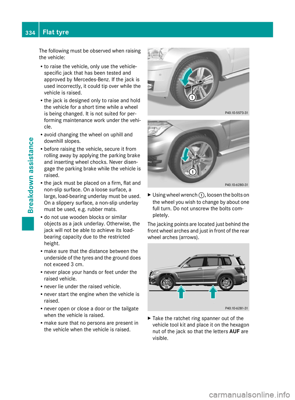
the vehicle when the vehicle is raised. X
Using wheel wrench :, loosen the bolts on
the wheel you wish to change by about one
full turn. Do not unscrew the bolts com-
pletely.
The jacking points are located just behind the
front wheel arches and just in front of the rear
wheel arches (arrows). X
Take the ratchet ring spanner out of the
vehicle tool kit and place it on the hexagon
nut of the jack so that the letters AUFare
visible. 334
Flat tyreBreakdown assistance
Page 358 of 381
Tyre pressure loss warning system
Important safety notes While the vehicle is in motion, the tyre pres-
sure loss warning system monitors the set
tyre pressure using the rotational speed of
the wheels. This enables the system to detect
significant pressure loss in a tyre. If the speed
of rotation of a wheel changes as a result of
a loss of pressure, a corresponding warning
message will appear in the multifunction dis-
play.
The tyre pressure warning system does not
warn you of an incorrectly set tyre pressure.
Observe the notes on the recommended tyre
pressure (Y page 353).
The tyre pressure loss warning system does
not replace the need to regularly check your
vehicle's tyre pressures, since an even loss of
pressure on several tyres at the same time
cannot be detected by the tyre pressure loss
warning system.
The tyre pressure monitor is not able to warn
you of a sudden loss of pressure, e.g. if the
tyre is penetrated by a foreign object. In the
event of a sudden loss of pressure, bring the
vehicle to a halt by braking carefully. Avoid
abrupt steering manoeuvres.
The function of the tyre pressure loss warning
system is limited or delayed if:
R snow chains are fitted to your vehicle's
tyres.
R road conditions are wintry.
R you are driving on sand or gravel.
R you adopt a very sporty driving style (cor-
nering at high speeds or driving with high
rates of acceleration).
R you are towing a very heavy or large trailer.
R you are driving with a heavy load (in the
vehicle or on the roof). Restarting the tyre pressure loss warn-
ing system Restart the tyre pressure loss warning system
if you have:
R
changed the tyre pressure
R changed the wheels or tyres
R fitted new wheels or tyres
X Before restarting, consult the table of tyre
pressures on the inside of the fuel filler flap
to ensure that the tyre pressure in all four
tyres is set correctly for the respective
operating conditions.
The tyre pressure loss warning system can
only give reliable warnings if you have set
the correct tyre pressure. If an incorrect
tyre pressure is set, these incorrect values
will be monitored.
X Observe the notes in the section on tyre
pressures (Y page 353).
Restarting using the 4-button multifunc-
tion steering wheel
X Make sure that the key is in position 2in
the ignition lock.
X Press the Vbutton to select Tyre
Tyre
pressure Menu: R pressure Menu: R.
X Press the Cbutton.
The RFI active Restart: R
RFI active Restart: R message
appears in the multifunction display.
X Press the Cbutton.
The Tyre
Tyre press.
press. OK?
OK?message appears in
the multifunction display.
If you wish to confirm the restart:
X Press the Wbutton.
The Run Flat Indicator restarted Run Flat Indicator restarted
message appears in the multifunction dis-
play.
After a teach-in period, the tyre pressure
loss warning system will monitor the set
tyre pressures of all four tyres.
or Tyre pressure
355Wheels and tyres Z
Page 359 of 381
If you wish to cancel the restart:
X
Press the Xbutton.
The tyre pressure values stored at the last
restart will continue to be monitored.
Restarting using the 12-button multifunc-
tion steering wheel
X Make sure that the key is in position 2in
the ignition lock.
X Press the =or; button to select the
Service
Service menu.
X Press the 9or: button to select
Tyre pressure Tyre pressure .
X Press the abutton.
The Run Flat Indicator active
Run Flat Indicator active
Restart
Restart with
withOK
OKmessage appears in the
multifunction display.
If you wish to confirm the restart:
X Press the abutton.
The Tyre press. now OK? Tyre press. now OK? message
appears in the multifunction display.
X Press the 9or: button to select
Yes
Yes.
X Press the abutton.
The Run Flat Indicator restarted
Run Flat Indicator restarted
message appears in the multifunction dis-
play.
After a teach-in period, the tyre pressure
loss warning system will monitor the set
tyre pressures of all four tyres.
or
If you wish to cancel the restart:
X Press the %button.
or
X If the Tyre press. now OK?
Tyre press. now OK? message
appears, use the 9or: button to
select Cancel
Cancel .
X Press the abutton.
The tyre pressure values stored at the last
restart will continue to be monitored. Changing a wheel
Flat tyre
The "Breakdown assistance" section
(Y page 329) contains information and notes
on how to deal with a flat tyre. It also provides
instructions on changing a wheel or fitting the
spare wheel/emergency spare wheel. Interchanging the wheels
G
WARNING
Interchanging the front and rear wheels may
severely impair the driving characteristics if
the wheels or tyres have different dimensions.
The wheel brakes or suspension components
may also be damaged. There is a risk of acci-
dent.
Interchange front and rear wheels only if the
wheels and tyres are of the same dimensions.
Interchanging the front and rear wheels of
differing dimensions can render the general
operating permit invalid.
Always pay attention to the instructions and
safety notices in the section on "Wheel
changing and spare wheel fitting"
(Y page 332).
The wear patterns on the front and rear tyres
differ, depending on the operating conditions.
Interchange the wheels before a clear wear
pattern has formed on the tyres. Front tyres
typically wear more on the shoulders and the
rear tyres in the centre.
On vehicles that have the same size front and
rear wheels, you can interchange the wheels
every 5,000km to 10,000 km depending on
the degree of tyre wear. Maintain the direc-
tion of tyre rotation.
Clean the contact surfaces of the wheel and
the brake disc thoroughly every time a wheel
is interchanged. Check the tyre pressure and,
if necessary, restart the tyre pressure loss
warning system or the tyre pressure monitor. 356
Changing a wheelWheels and tyres