2012 MERCEDES-BENZ G-CLASS SUV phone
[x] Cancel search: phonePage 282 of 357

motion, you must only do so if the traffic sit-
uation permits. Otherwise, you could be dis-
tracted from the traffic conditions, cause an
accident and injure yourself and others.
Two-way radios and fax equipment used with-
out low-reflection exterior aerials can inter-
fere with the vehicle's electronics and thereby
jeopardise the operating safety of the vehicle
and yours afety. Therefore, you must only use
this equipment if it is correctly connected to
a separate reflection-free exterio raerial. G
WARNING
Excessive levels of electromagnetic radiation
may cause damage to your health and the
health of others. Using an exterior aerial takes
into account current scientific discussions
relating to the possible health risk posed by
electromagnetic fields.
Mercedes-Benz recommends the use of an
approved exterior aerial. This ensures:
R optimal mobile phone reception quality in
the vehicle
R mutual influences between the vehicle
electronics and mobile phones are mini-
mised
An exterior aerial has the following advan-
tages:
R it conducts the electromagnetic fields gen-
erated by a wireless device to the exterior.
R the field strength in the vehicle interior is
lower than in a vehicle that does not have
an exterior aerial.
i There are various mobile phone brackets
that may be fitted in your vehicle; in some
cases, these are country-specific. You can
obtain these mobile phone brackets from a
qualified specialist workshop.
The functions and services available when
you use the phone depend on your mobile
phone model and service provider. Mobile telephone bracket in the stow-
age space
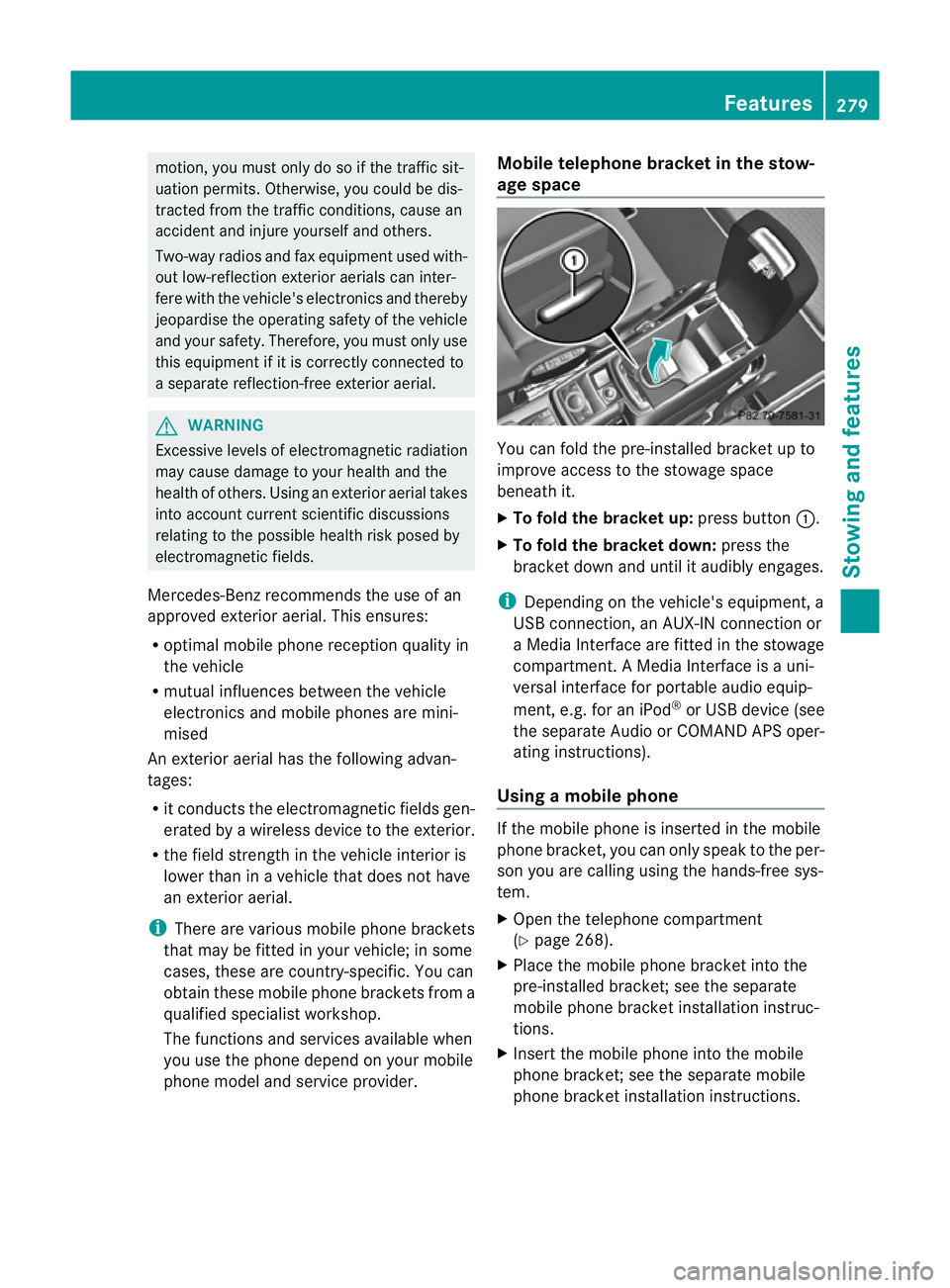
You can fold the pre-installed bracket up to
improve access to the stowage space
beneath it.
X
To fold the bracket up: press button:.
X To fold the bracket down: press the
bracket down and until it audibly engages.
i Depending on the vehicle's equipment, a
USB connection, an AUX-IN connection or
a Media Interface are fitted in the stowage
compartment. A Media Interface is a uni-
versal interface for portable audio equip-
ment, e.g. for an iPod ®
or USB device (see
the separate Audio or COMAND APS oper-
ating instructions).
Using amobile phone If the mobile phone is inserted in the mobile
phone bracket, you can only speak to the per-
son you are calling using the hands-free sys-
tem.
X
Open the telephone compartment
(Y page 268).
X Place the mobile phone bracket into the
pre-installed bracket; see the separate
mobile phone bracket installation instruc-
tions.
X Inser tthe mobile phone into the mobile
phone bracket; see the separate mobile
phone bracket installation instructions. Features
279Stowing and features Z
Page 283 of 357

Operating the mobile phone
You can operate the telephon
eusing the
6 and~ buttons on the multifunction
steering wheel. You can operate other mobile
phone functions via the on-board computer
(Y page 218).
When you remove the key from the ignition
lock, the mobile phone remains switched on
for approximately ten minutes (run-on time).
If you make a call during this time, the mobile
phone will be switched off approximately ten
minutes after you have ended the call. Garage door opener
Important safety notes You can use the HomeLink
®
garage door
opener integrated into the rear-view mirror to
operate up to three different gate/garage
door opener systems.
i The garage door opener is only available
for certain countries. Observe the legal
requirements for each individual country.
The HomeLink ®
garage door opener is
compatible with most European garage and
gate opener drives. More information on
HomeLink ®
and/or compatible products is
available from:
R any Mercedes-Benz Service Centre
R the HomeLink ®
hotline
(0) 08000 466 354 65 (free of charge) or
+49 (0) 6838 907 277 (charges apply)
R on the Internet at:
http://www.homelink.com
Programming the remote control Programming
G
WARNING
Only press the button on the integrated
garage door opener if there are no persons or
objects present within the sweep of the garage door. Persons could otherwise be
injured as the door moves.
Remote control in the rear-view mirror
:
Indicator lamp
;=? Transmitter buttons
A Garage door remote control
B Transmitter button on the garage
door remote control
Garage door remote control Ais not part of
the garage door opener.
i To achieve the best result, insert new bat-
teries in garage door remote control Aof
your garage door drive before program-
ming.
X Delete the memory of the integrated
remote control (Y page 283) before pro-
gramming it for the first time.
X Turn the key to position 2(Ypage 143) in
the ignition lock.
X Press and hold transmitter button ;,=
or ?.
After a short time, indicator lamp :will
start flashing. It flashes abouto nce per
second.
i Indicato rlamp :flashes immediately
th ef irst tim ethat the transmitter button is
programmed. If this transmitter button has
already been programmed, indicator
lamp :will only start flashing at a rate of
once a second after 20 seconds have
elapsed.
X Keep the transmitter button depressed. 280
FeaturesStowing and features
Page 295 of 357

Checking the oil level using the oil dip-
stick
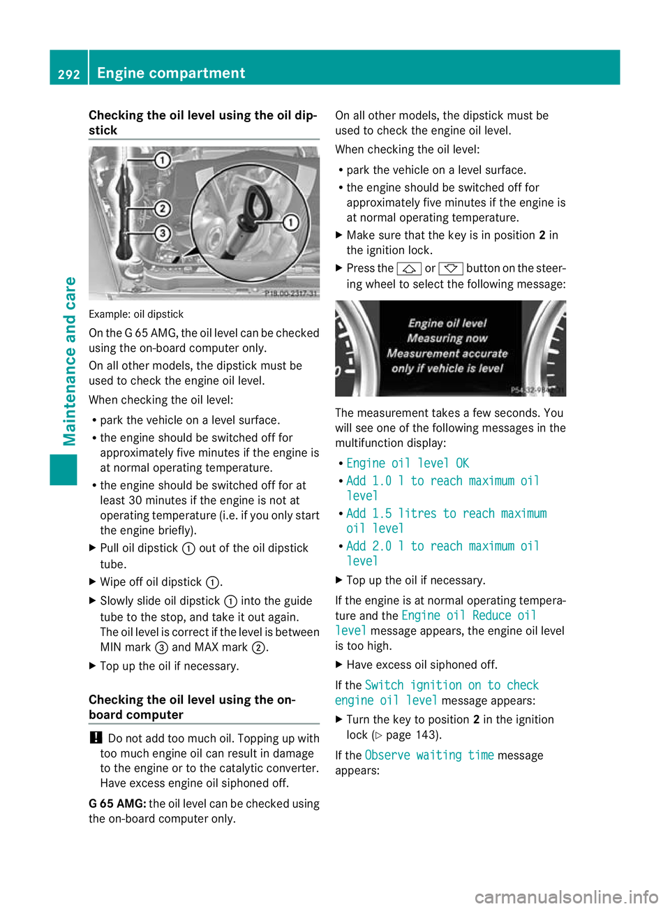
Example
:oil dipstick
On the G 65 AMG, the oil level can be checked
using the on-board computer only.
On all other models, the dipstick must be
used to chec kthe engine oil level.
When checking the oil level:
R park the vehicle on a level surface.
R the engine should be switched off for
approximately five minutes if the engine is
at normal operating temperature.
R the engine should be switched off for at
least 30 minutes if the engine is not at
operating temperature (i.e. if you only start
the engine briefly).
X Pull oil dipstick :out of the oil dipstick
tube.
X Wipe off oil dipstick :.
X Slowly slide oil dipstick :into the guide
tube to the stop, and take it out again.
The oil level is correct if the level is between
MIN mark =and MAX mark ;.
X Top up the oil if necessary.
Checking the oil level using the on-
board computer !
Do not add too much oil. Topping up with
too much engine oil can result in damage
to the engine or to the catalytic converter.
Have excess engine oil siphoned off.
G6 5 AMG: the oil level can be checked using
the on-board computer only. On all other models, the dipstic
kmust be
used to chec kthe engine oil level.
When checking the oil level:
R park the vehicle on a level surface.
R the engine should be switched off for
approximately five minutes if the engine is
at normal operating temperature.
X Make sure that the key is in position 2in
the ignition lock.
X Press the &or* button on the steer-
ing wheel to select the following message: The measurement takes a few seconds. You
will see one of the following messages in the
multifunction display:
R Engine oil level OK R
Add 1.0 l to reach maximum oil level
R
Add 1.5 litres to reach maximum oil level
R
Add 2.0 l to reach maximum oil level
X
Top up the oil if necessary.
If the engine is at normal operating tempera-
ture and the Engine oil Reduce oil level message appears, the engine oil level
is too high.
X Have excess oil siphoned off.
If the Switch ignition on to check engine oil level message appears:
X Turn the key to position 2in the ignition
lock (Y page 143).
If the Observe waiting time message
appears: 292
Engine compartmentMaintenance and care
Page 296 of 357

X
If the engine is at normal operating tem-
perature: repeat the measuremen tafter
about five minutes.
X If the engine is not at normal operating
temperature: (e.g. if the engine was only
started briefly) repeat the measurement
after about 30 minutes.
If the Engine oil level Not when engine on message appears:
X Switch off the engine.
X If the engine is at normal operating tem-
perature: wait about five minutes before
carrying out the measurement.
X If the engine is not at normal operating
temperature: e.g. if the engine was only
started briefly, wait approximately
30 minutes before carrying out the meas-
urement.
i If you wish to cancel the measurement,
press the *or& button on the mul-
tifunction steering wheel.
Adding engine oil H
Environmental note
When topping up the oil, take care not to spill
any. If oil enters the soil or waterways, it is
harmful to the environment.
! Do not add too much oil .Ifthe oil level is
above the "max" mark on the dipstick, too
much oil has been added. This can lead to
damage to the engine or the catalytic con-
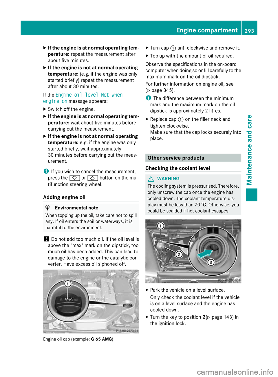
verter. Have excess oil siphoned off. Engine oil cap (example:
G 65 AMG) X
Turn cap :anti-clockwise and remove it.
X Top up with the amount of oil required.
Observe the specifications in the on-board
computer when doing so or fill carefully to the
maximum mark on the oil dipstick.
For further information on engine oil, see
(Y page 345).
i The difference between the minimum
mark and the maximum mark on the oil
dipstick is approximately 2litres.
X Replace cap :on the filler neck and
tighten clockwise.
Make sure that the cap locks securely into
place. Other service products
Checking the coolant level G
WARNING
The cooling system is pressurised. Therefore,
only unscrew the cap once the engine has
cooled down. The coolan ttemperature dis-
play must be less than 70 †. Otherwise, you
could be scalded if hot coolant escapes. X
Park the vehicle on a level surface.
Only chec kthe coolant level if the vehicle
is on a level surface and the engine has
cooled down.
X Turn the key to position 2(Ypage 143) in
the ignition lock. Engine compartment
293Maintenance and care Z
Page 331 of 357

ured at a filling station with a pressure gauge.
The tyre pressures shown by the on-board
computer refer to those measured at sea
level. At high altitudes, the tyre pressure val-
ues indicated by a pressur
egauge are higher
than those shown by the on-board computer.
In this case, do no treduce the tyre pressures.
The operation of the tyre pressure monitor
can be affected by interference from radio
transmitting equipment (e.g. radio head-
phones, two-way radios) that may be being
operated in or near the vehicle.
Checking tyre pressure electronically X
Make sure that the key is in position 2
(Y page 143)in the ignition lock.
X Press the =or; button on the steer-
ing wheel to select the Serv. menu.
X Press the 9or: button to select
Tyre pressure .
X Press the abutton.
The curren ttyre pressur efor each wheel
will be displayed in the multifunction dis-
play.
If the vehicle has been parked for over
20 minutes, the message Tyre pressureswill be displayed after a few
minutes of driving appears.
After a teach-in period, the tyre pressure
monitor automatically recognises new
wheels or new sensors. As long as a clear
allocation of the tyre pressure values to the
individual wheels is not possible, the Tyrepressure monitor active display mes-
sage is shown instead of the tyre pressure
display .The tyre pressures are already being
monitored.
i If a spare wheel is fitted, the system may
continue to show the tyre pressure of the
wheel that has been removed for a few
minutes. If this occurs, note that the value
displayed for the position where the spare
tyre is fitted is not the same as the spare
tyre's current tyre pressure. Warning messages of the tyre pressure
monitor If the tyre pressure monitor detects a signifi-
cant pressure loss on one or more tyres, a
warning message is shown in the multifunc-
tion display.
Awarning tone also sounds and
the tyre pressure warning lamp lights up in
the instrument cluster.
Each tyre that is affected by a significant loss
of pressure is highlighted in the pressure dis-
play.
X If the Please correct tyre pres‐ surePlease correct tyre pressure
message appears in the multifunction dis-
play, check the tyre pressure on all four
wheels and correct it if necessary.
i If the wheel positions on the vehicle are
interchanged, the tyre pressures may be
displayed for the wrong positions for a
short time. This is rectified after a few
minutes of driving, and the tyre pressures
are displayed for the correct positions.
Restarting the tyre pressure monitor When you restar
tthe tyre pressure monitor,
all existing warning messages are deleted and
the warning lamps go out. The monitor uses
the currently set tyre pressures as the refer-
ence values for monitoring. In most cases, the
tyre pressure monitor will automatically
detect the new referencev alues after you
have changed the tyre pressure .However,
you can also define reference values man-
ually as described here.
X Use the table on the inside of the fuel filler
flap to ensure that the tyre pressure is set
correctly in all four tyres for the current
operating conditions.
Also observe the notes in the section on
tyre pressures (Y page 325).
X Make sure that the key is in position 2
(Y page 143) in the ignition lock.
X Press the =or; button on the steer-
ing wheel to select the Serv. menu.328
Tyre pressureWheels and tyres
Page 342 of 357

may invalidate the vehicle's general operating
permit.
This is the case:
R if they cause a change of the vehicle type
from that for which the vehicle's general
operating permit was granted
R if other road users could be endangered
R if the emission or noise levels are adversely
affected
Always specify the vehicle identification num-
ber (VIN) (Y page 340) and the engine num-
ber (Y page 341) when ordering genuine
Mercedes-Benz parts. Vehicle electronics
Tampering with the engine electron-
ics G
WARNING
Always have work on the engine electronics
and related components carried out at a quali-
fied specialist workshop .Otherwise, the vehi-
cle's operating safety could be affected.
! Only have work carried ou tonthe engine
electronics and its associated parts, such
as control units, sensors and connector
leads, at a qualified specialist workshop.
Vehicle components may otherwise wear
more quickly and the vehicle's operating
permit may be invalidated. Retrofitting of two-way radios and
mobile phones (RF transmitters) G
WARNING
Incorrect retrofitting of RF transmitters can
cause the vehicle electronicst o malfunction.
The vehicle's operating safety and thus your
own safety are impaired.
Have aftermarket radio frequency transmit-
ting equipment installed at a qualified spe-
cialist workshop. G
WARNING
Incorrect retrofitting of RF transmitters can
lead to increased electromagnetic radiation in
the vehicle interior. Using an exterior aerial
takes into account current scientific discus-
sions relating to the possible health hazards
that may result from electromagnetic fields.
Have aftermarket radio frequency transmit-
ting equipment installed at a qualified spe-
cialist workshop.
! The operating permit may be invalidated
if the instructions for installation and use of
RF transmitters are not observed.
In particular, the following conditions must
be complied with:
R only approved wavebands may be used.
R the maximum permissible output in
these wavebands must be complied with.
R the approved aerial positions must be
complied with. Approved aerial positions
:
Front roof area
; Rear wing
i When fitting an aerial on the front roof
area of vehicles with a sliding sunroof,
observe the sweeping range of the roof.
On the rear wing, it is recommended to
position the aerial on the side of the vehicle
that faces the centre of the road.
Use Technical Specification ISO/TS 21609
(Road Vehicles –"EMC guidelines for fitting
aftermarket radio frequency transmitting
equipment") when retrofitting RF (radio fre- Vehicle electronics
339Technical data Z
Page 343 of 357

quency) transmitters
.Comply with the legal
requirements for add-on parts.
If your vehicle has fittings for two-way radio
equipment, use the power supply or aerial
connections intended for use with the basic
wiring. Be sure to observe the manufacturer's
additional instructions when installing.
Deviations with respect to wavebands, maxi-
mum transmission outputs or aerial positions
must be approved by Mercedes-Benz.
The maximum transmission output (PEAK) at
the base of the aerial must not exceed the
following values: Waveband Maximum
transmission
output( PEAK) Short wave (f < 54 MHz) 100 W
4 m waveband 30 W
2 m waveband 50 W
Trunked radio/Tetra 35 W
70 cm waveband 35 W
GSM/DCS/PCS
850/900/1800/1900 10 W
UMTS/LTE 10 W
The following can be used in the vehicle with-
out restrictions:
R
RF transmitters with amaximum transmis-
sion output of up to 100 mW
R mobile phones (GSM/DCS/PCS/UMTS/
LTE)
There are no restriction swhen positioning the
aerial on the outside of the vehicle for the fol-
lowing wavebands:
R Trunked radio/Tetra
R 70 cm waveband
R GSM/DCS/PCS
R UMTS/LTE Identification plates
Vehicle identification plate with vehi-
cle identification number (VIN) and
paint code number
X
Open the front left-hand door.
You will see vehicle identification plate :. Example: vehicle identification plate
:
Vehicle identification plate
; Vehicle manufacturer (Daimler AG)
= EU type approval number (only for certain
countries)
? VIN
A Maximum permissible gross vehicle
weight (kg)
B Maximum permissible mass of vehicle/
trailer combination (kg)
C Maximum permissible front axle load (kg)
D Maximum permissible rear axle load (kg)
E Paint code
i The data shown on the vehicle identifica-
tion plate is example data. This data is dif-
ferent for every vehicle and can deviate 340
Identification platesTechnical data