2012 MERCEDES-BENZ G-CLASS SUV ignition
[x] Cancel search: ignitionPage 230 of 357
X
Press the %button on the steering
wheel.
X Press ato confirm Yes .
The RACETIMER is interrupted if you stop the
vehicle and turn the key to position
1(Y page 143) in the ignition lock. If you turn
the key to position 2or 3(Y page 143) and
then press ato confirm Start , timing is
continued.
Resetting the current lap
X Stop the RACETIMER (Y page 226).
X Press =or; to select Reset Lap .
X Press ato reset the lap time to "0".
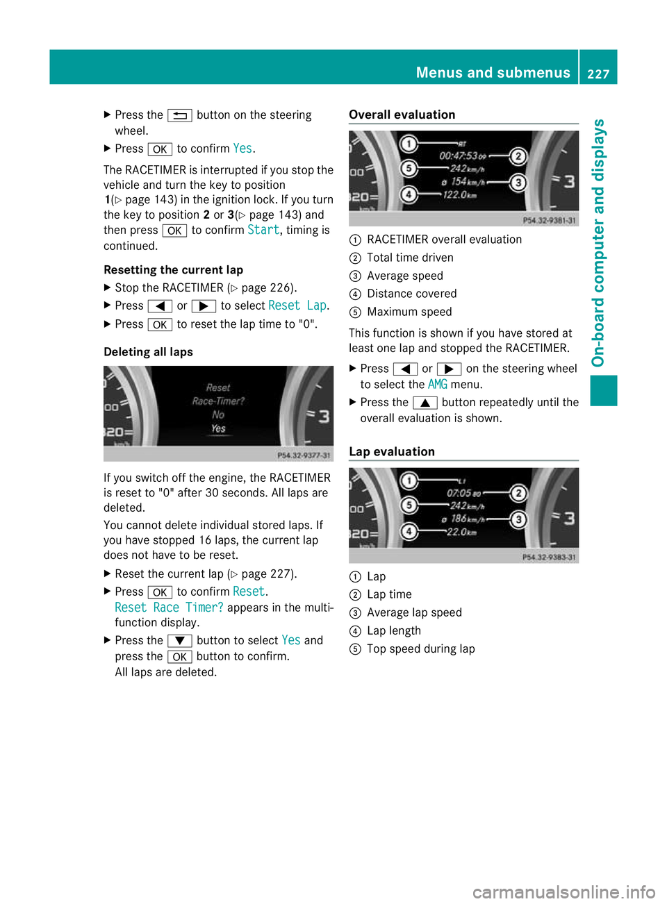
Deleting all laps If you switch off the engine, the RACETIMER
is reset to "0" after 30 seconds. All laps are
deleted.
You cannot delete individual stored laps. If
you have stopped 16 laps, the curren tlap
does no thave to be reset.
X Reset the curren tlap (Y page 227).
X Press ato confirm Reset .
Reset Race Timer? appears in the multi-
function display.
X Press the :button to select Yes and
press the abutton to confirm.
All laps are deleted. Overall evaluation :
RACETIMER overall evaluation
; Total time driven
= Average speed
? Distance covered
A Maximum speed
This function is shown if you have stored at
least one lap and stopped th eRACETIMER.
X Press =or; on the steering wheel
to select the AMG menu.
X Press the 9button repeatedly until the
overall evaluation is shown.
Lap evaluation :
Lap
; Lap time
= Average lap speed
? Lap length
A Top speed during lap Menus and submenus
227On-board computer and displays Z
Page 231 of 357
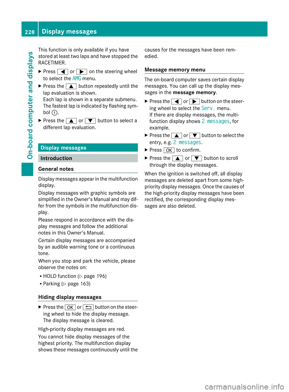
This function is only available if you have
stored at least two laps and have stopped the
RACETIMER.
X
Press =or; on the steering wheel
to select the AMG menu.
X Press the 9button repeatedly until the
lap evaluation is shown.
Each lap is shown in a separate submenu.
The fastest lap is indicated by flashing sym-
bol :.
X Press the 9or: button to select a
different lap evaluation. Display messages
Introduction
General notes Display messages appear in the multifunction
display.
Display messages with graphic symbols are
simplified in the Owner's Manual and may dif-
fer from the symbols in the multifunction dis-
play.
Please respond in accordance with the dis-
play messages and follow the additional
notes in this Owner's Manual.
Certain display messages are accompanied
by an audible warning tone or a continuous
tone.
When you stop and park the vehicle, please
observe the notes on:
R
HOLD function (Y page 196)
R Parking (Y page 163)
Hiding display messages X
Press the aor% button on the steer-
ing wheel to hide the display message.
The display message is cleared.
High-priority display messages are red.
You cannot hide display messages of the
highest priority. The multifunction display
shows these messages continuously until the causes for the messages have been rem-
edied.
Message memor
ymenu The on-board compute
rsaves certain display
messages .You can call up the display mes-
sages in the message memory.
X Press the =or; button on the steer-
ing wheel to select the Serv. menu.
If there are display messages, the multi-
function display shows 2 messages , for
example.
X Press the 9or: button to select the
entry, e.g. 2 messages .
X Press ato confirm.
X Press the 9or: button to scroll
through the display messages.
When the ignition is switched off, all display
messages are deleted apart from some high-
priority display messages. Once the causes of
the high-priority display messages have been
rectified, the corresponding display mes-
sages are also deleted. 228
Display messagesOn-board computer and displays
Page 240 of 357
Display messages Possible causes/consequences and
M Solutions
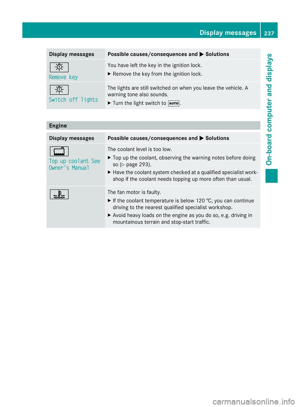
b
Remove key You have lef
tthe key in the ignition lock.
X Remove the key from the ignition lock. b
Switch off lights The lights are still switched on when you leave the vehicle. A
warning tone also sounds.
X
Turn the light switch to Ã.Engine
Display messages Possible causes/consequences and
M Solutions
+
Top
up coolant See
Owner's Manual The coolant level is too low.
X
Top up the coolant, observing the warning notes before doing
so (Y page 293).
X Have the coolant system checked at a qualified specialist work-
shop if the coolant needs topping up more often than usual. ? The fan motor is faulty.
X
If the coolant temperature is below 120 †, you can continue
driving to the nearest qualified specialist workshop.
X Avoid heavy loads on the engine as you do so, e.g. driving in
mountainous terrain and stop-start traffic. Display messages
237On-board computer and displays Z
Page 262 of 357
Problem Possible causes/consequences and
M Solutions
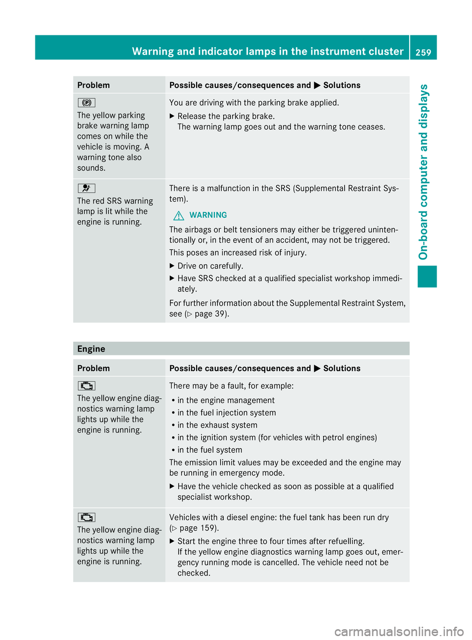
!
The yellow parking
brake warning lamp
comes on while the
vehicle is moving. A
warning tone also
sounds.
You are driving with the parking brake applied.
X
Release the parking brake.
The warning lamp goes out and the warning tone ceases. 6
The red SRS warning
lamp is lit while the
engine is running.
There is a malfunction in the SRS (Supplemental Restraint Sys-
tem).
G WARNING
The airbags or belt tensioners may either be triggered uninten-
tionally or, in the event of an accident, may not be triggered.
This poses an increased risk of injury.
X Drive on carefully.
X Have SRS checked at a qualified specialist workshop immedi-
ately.
For further information about the Supplemental Restraint System,
see (Y page 39). Engine
Problem Possible causes/consequences and
M Solutions
;
The yellow engine diag-
nostics warning lamp
lights up while the
engine is running.
There may be a fault, for example:
R
in the engine management
R in the fuel injection system
R in the exhaust system
R in the ignition system (for vehicles with petrol engines)
R in the fuel system
The emission limit values may be exceeded and the engine may
be running in emergency mode.
X Have the vehicle checked as soon as possible at a qualified
specialist workshop. ;
The yellow engine diag-
nostics warning lamp
lights up while the
engine is running.
Vehicles with a diesel engine: the fuel tank has been run dry
(Y
page 159).
X Start the engine three to four times after refuelling.
If the yellow engine diagnostics warning lamp goes out, emer-
gency running mode is cancelled. The vehicle need not be
checked. Warning and indicator lamps in the instrument cluster
259On-board computer and displays Z
Page 270 of 357
If the rear bench seat is not occupied:
X
insert the belt tongue on the outer seat
belts into the buckle of opposite seat
belt :.
X secure the load with sufficiently strong and
wear-resistant lashing material.
X pad sharp edges for protection.
i Lashing material that has been checked
in accordance with applicable standards is
available at any qualified specialist work-
shop. Stowage areas
Stowage compartments
Important safety notes G
WARNING
The stowage compartments must be closed
when items are stored in them. Luggage nets
are not designed to secure heavy items of
luggage.
You or other vehicle occupants could be
injured by objects being thrown around if you:
R brake sharply
R change direction suddenly
R are involved in an accident
Sharp-edged and fragile objects must not be
placed in the luggage net.
Do not place hard objects in the map pockets.
Objects must not protrude from the map
pockets. Front stowage compartments Glove compartment
X
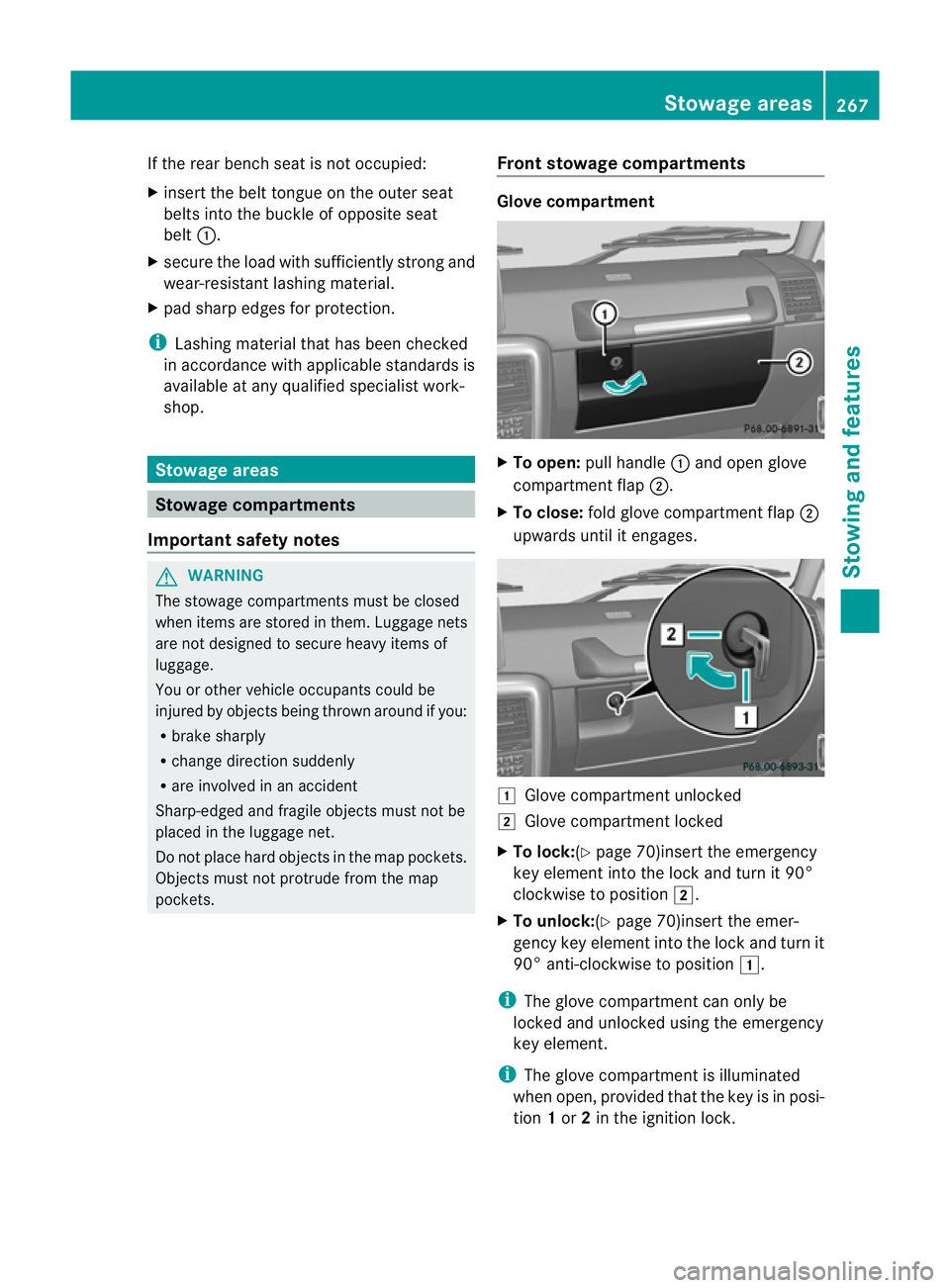
To open: pull handle :and open glove
compartment flap ;.
X To close: fold glove compartment flap ;
upwards until it engages. 1
Glove compartment unlocked
2 Glove compartment locked
X To lock:(Y page 70)insert the emergency
key element into the lock and turn it 90°
clockwise to position 2.
X To unlock:(Y page 70)insert the emer-
gency key element into the lock and turn it
90° anti-clockwise to position 1.
i The glove compartment can only be
locked and unlocked using the emergency
key element.
i The glove compartment is illuminated
when open, provided that the key is in posi-
tion 1or 2in the ignition lock. Stowage areas
267Stowing and features Z
Page 281 of 357
i
You can use the cigarette lighter socket
for accessories up to 180 W
(Y page 278). 12
Vsockets
General notes !
If you are simultaneously using all three
sockets in the vehicle, make sure that you
do not exceed the maximum current draw
of 45 A. Otherwise, you will overload the
fuses.
The sockets can be used for accessories with
am aximum current draw of 180 W(15 A), e.g.
lamps or chargers for mobile phones.
If you use the sockets for long periods when
the engine is switched off, the battery may
discharge.
X Turn the key to position 2in the ignition
lock.
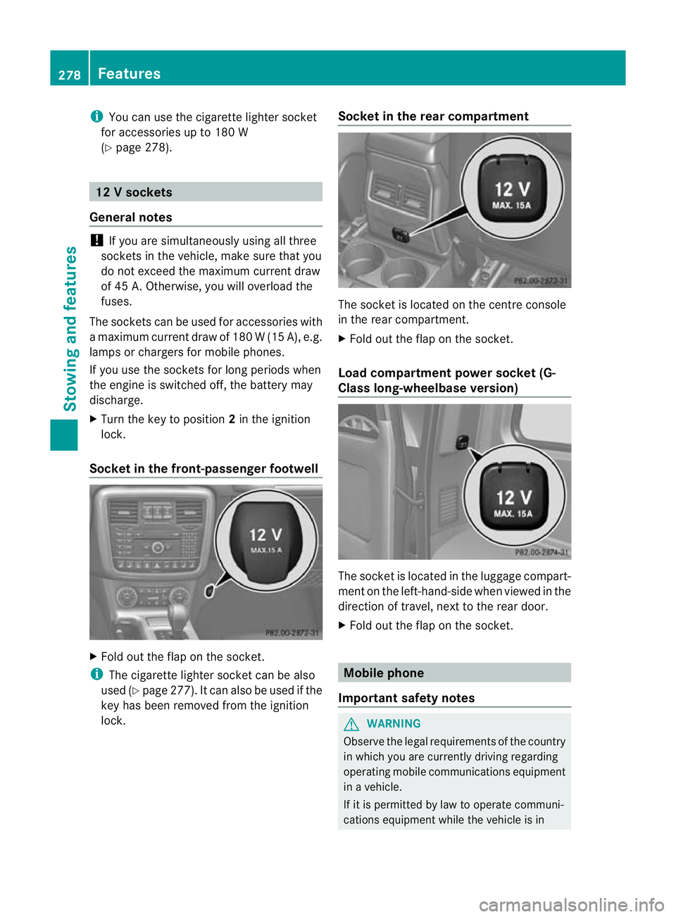
Socket in the front-passenge rfootwell X
Fold out the flap on th esocket.
i The cigarette lighter socket can be also
used (Y page 277). It can also be used if the
key has been removed from the ignition
lock. Socket in the rear compartment The socket is located on the centre console
in the rear compartment.
X
Fold out the flap on the socket.
Load compartment power socket (G-
Class long-wheelbase version) The socket is located in the luggage compart-
ment on the left-hand-side when viewed in the
direction of travel, next to the rear door.
X Fold out the flap on the socket. Mobile phone
Important safety notes G
WARNING
Observe the legal requirements of the country
in which you are currently driving regarding
operating mobile communications equipment
in a vehicle.
If it is permitted by law to operate communi-
cations equipment while the vehicle is in 278
FeaturesStowing and features
Page 283 of 357

Operating the mobile phone
You can operate the telephon
eusing the
6 and~ buttons on the multifunction
steering wheel. You can operate other mobile
phone functions via the on-board computer
(Y page 218).
When you remove the key from the ignition
lock, the mobile phone remains switched on
for approximately ten minutes (run-on time).
If you make a call during this time, the mobile
phone will be switched off approximately ten
minutes after you have ended the call. Garage door opener
Important safety notes You can use the HomeLink
®
garage door
opener integrated into the rear-view mirror to
operate up to three different gate/garage
door opener systems.
i The garage door opener is only available
for certain countries. Observe the legal
requirements for each individual country.
The HomeLink ®
garage door opener is
compatible with most European garage and
gate opener drives. More information on
HomeLink ®
and/or compatible products is
available from:
R any Mercedes-Benz Service Centre
R the HomeLink ®
hotline
(0) 08000 466 354 65 (free of charge) or
+49 (0) 6838 907 277 (charges apply)
R on the Internet at:
http://www.homelink.com
Programming the remote control Programming
G
WARNING
Only press the button on the integrated
garage door opener if there are no persons or
objects present within the sweep of the garage door. Persons could otherwise be
injured as the door moves.
Remote control in the rear-view mirror
:
Indicator lamp
;=? Transmitter buttons
A Garage door remote control
B Transmitter button on the garage
door remote control
Garage door remote control Ais not part of
the garage door opener.
i To achieve the best result, insert new bat-
teries in garage door remote control Aof
your garage door drive before program-
ming.
X Delete the memory of the integrated
remote control (Y page 283) before pro-
gramming it for the first time.
X Turn the key to position 2(Ypage 143) in
the ignition lock.
X Press and hold transmitter button ;,=
or ?.
After a short time, indicator lamp :will
start flashing. It flashes abouto nce per
second.
i Indicato rlamp :flashes immediately
th ef irst tim ethat the transmitter button is
programmed. If this transmitter button has
already been programmed, indicator
lamp :will only start flashing at a rate of
once a second after 20 seconds have
elapsed.
X Keep the transmitter button depressed. 280
FeaturesStowing and features
Page 284 of 357

X
Point transmitter button Bof garage door
remote control Atowards the transmitter
buttons on the rear-view mirror at a dis-
tance of 5to 30 cm.
i The distance between garage door
remote control Aand the integrated
garage door opener depends on the system
of the garage door drive. Several attempts
may be required. You should test every
position for at least 20 seconds before try-
ing another position.
X Keep transmitter button Bon garage door
remote control Apressed until indicator
lamp :starts to flash rapidly.
The programming has been successful if
indicator lamp :flashes rapidly.
X Release transmitter buttons ;,=or?
on the integrated remot econtrol and trans-
mitter button Bon the garage door remote
control.
If indicator lamp :goes out after approx-
imately 20 seconds and has not flashed rap-
idly:
X Release transmitter buttons ;,=or?
on the integrated remote control and trans-
mitter button Bon the garage door remote
control.
X Repeat the procedure for the other trans-
mitter buttons. When doing so, vary the
distance between the garage door's
remote control and the transmitter buttons
in the rear-view mirror.
i If the garage door system works with a
rolling code, you must synchronise the
remote control integrated into the rear-
view mirror with the garage door system
receiver after programming.
You will find further information in the
garage door system's operating instruc-
tions, e.g. the section son"Synchronising
the transmitter" or "Registering a new
transmitter". You can also call the hotline
mentioned above. Synchronising the rolling code
Remote control in the rear-view mirror
:
Indicator lamp
;=? Transmitter buttons
A Garage doo rremote control
B Transmitter button on the garage
door remote control
Your vehicle must be within range of the
garage door or exterior gate drive. Make sure
that neither your vehicle nor any persons/
objects are present within the sweep of the
door or gate.
Observe the safety notes when performing
the rolling code synchronisation
(Y page 280).
X Turn the key to position 2(Ypage 143) in
the ignition lock.
X Press the programming button of the door
or gate drive (see the door or gate drive
operating instructions, e.g. under "Pro-
gramming of additional remote controls").
i Usually, you now have 30 seconds to ini-
tiate the next step.
X Press previously programmed button ;,
= or? of the integrated garage door
opener until the door closes.
The rolling code synchronisation is then
complete. Features
281Stowing and features Z