2012 MERCEDES-BENZ E-CLASS COUPE clock
[x] Cancel search: clockPage 227 of 389
X
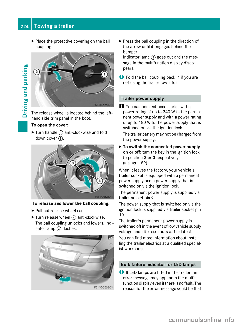
Place the protective covering on the ball
coupling. The release wheel is located behind the left-
hand side trim panel in the boot.
To open the cover:
X
Turn handle :anti-clockwise and fold
down cover ;. To release and lower the ball coupling:
X Pull out release wheel ?.
X Turn release wheel ?anti-clockwise.
The ball coupling unlocks and lowers. Indi-
cator lamp =flashes. X
Press the ball coupling in the direction of
the arrow until it engages behind the
bumper.
Indicator lamp =goes out and the mes-
sage in the multifunction display disap-
pears.
i Fold the ball coupling back in if you are
not using the trailer tow hitch. Trailer power supply
! You can connect accessories with a
power rating of up to 240 W to the perma-
nent power supply and with a power rating
of up to 180 W to the power supply that is
switched on via the ignition lock.
The trailer battery may not be charged from
the power supply.
X To switch the connected power supply
on or off: turn the key in the ignition lock
to position 2or 0respectively
(Y page 159).
When it leaves the factory, your vehicle's
trailer socket is equipped with a permanent
power supply and a power supply that is
switched on via the ignition lock.
The permanen tpower supply is supplied via
trailer socket pin 9.
The power supply that is switched on via the
ignition lock is supplied via trailer socket pin
10.
The trailer's permanent power supply is
switched off in the event of low vehicle supply
voltage and after six hours at the latest.
You can find more information about instal-
ling the trailer electric sataqualified special-
ist workshop. Bulb failure indicator for LED lamps
i If LED lamps are fitted in the trailer, an
error message may appear in the multi-
function display even if there is no fault. The
reason for the error message could be that 224
Towing
atrailerDriving an d parking
Page 228 of 389
the current has fallen below the minimum
of 50 mA.
To ensure reliable operatio nofthe bulb failure
indicator, each LED chain in the trailer lighting
must be guaranteed a minimum current of
50 mA. Trailer with 7-pin connector
General notes Trailers with 7-pin connector:
you can
make a connection to the 13-pin connector
on the ball coupling using an adapter plug or,
if necessary, an adapter cable. Both can be
obtained in a qualified specialist workshop.
Fitting the adapter !
Make sure that there is sufficient cable
play so that the cable cannot become
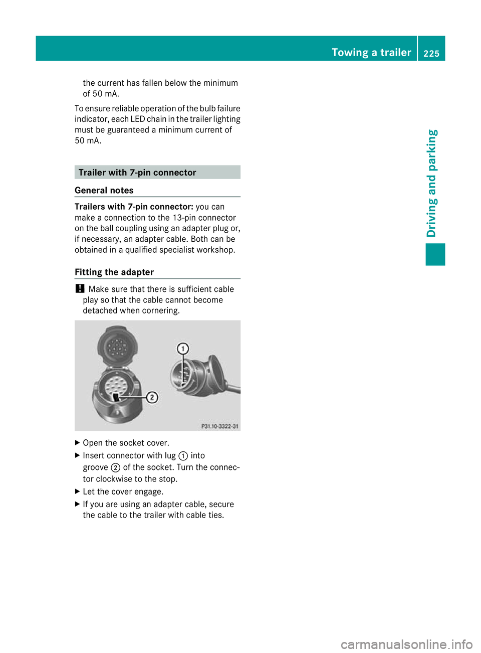
detached when cornering. X
Open the socket cover.
X Insert connector with lug :into
groove ;of the socket. Turn the connec-
tor clockwise to the stop.
X Let the cover engage.
X If you are using an adapter cable, secure
the cable to the trailer with cable ties. Towing
atrailer
225Driving an d parking Z
Page 233 of 389
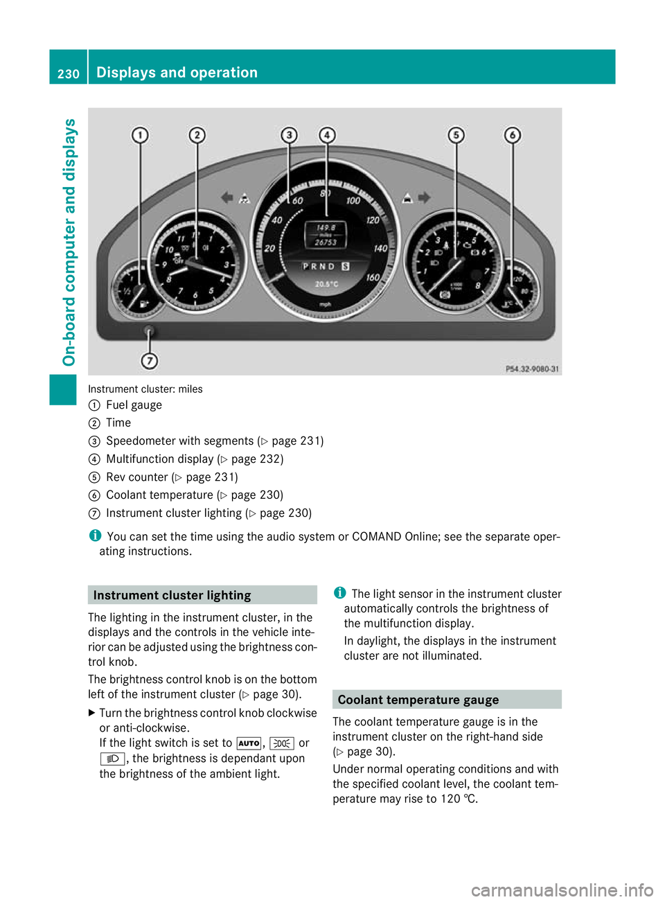
Instrument cluster: miles
:
Fuel gauge
; Time
= Speedometer with segments (Y page 231)
? Multifunction display (Y page 232)
A Rev counter (Y page 231)
B Coolant temperature (Y page 230)
C Instrument cluster lighting (Y page 230)
i You can set the time using the audio system or COMAND Online; see the separate oper-
ating instructions. Instrument clusterl
ighting
The lighting in the instrumen tcluster, in the
displays and the controls in the vehicle inte-
rior can be adjusted using the brightness con-
trol knob.
The brightness control knob is on the bottom
left of the instrument cluster (Y page 30).
X Turn the brightness control knob clockwise
or anti-clockwise.
If the light switch is set to Ã,Tor
L, the brightness is dependant upon
the brightness of the ambien tlight. i
The light sensor in the instrumen tcluster
automatically controls the brightness of
the multifunction display.
In daylight, the displays in the instrument
cluster are not illuminated. Coolant temperature gauge
The coolan ttemperature gauge is in the
instrument cluster on the right-hand side
(Y page 30).
Under normal operating conditions and with
the specified coolant level, the coolant tem-
perature may rise to 120 †. 230
Displays and operationOn-board computer and displays
Page 290 of 389
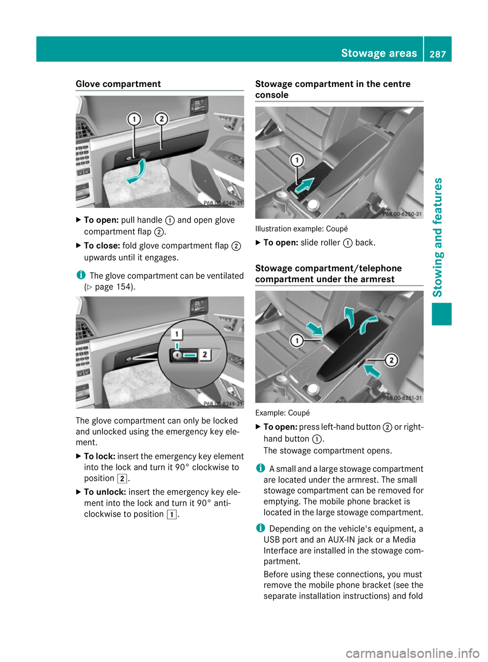
Glove compartment
X
To open: pull handle :and open glove
compartment flap ;.
X To close: fold glove compartment flap ;
upwards until it engages.
i The glove compartment can be ventilated
(Y page 154). The glove compartment can only be locked
and unlocked using the emergency key ele-
ment.
X To lock: insert the emergency key element
into the lock and turn it 90° clockwise to
position 2.
X To unlock: insert the emergency key ele-
ment into the lock and turn it 90° anti-
clockwise to position 1. Stowage compartment in the centre
console Illustration example: Coupé
X
To open: slide roller :back.
Stowage compartment/telephone
compartment under the armrest Example: Coupé
X
To open: press left-hand button ;or right-
hand button :.
The stowage compartment opens.
i Asmall and a large stowage compartment
are located under the armrest. The small
stowage compartment can be removed for
emptying. The mobile phone bracket is
located in the large stowage compartment.
i Depending on the vehicle's equipment, a
USB port and an AUX-IN jack or a Media
Interface are installed in the stowage com-
partment.
Before using these connections, you must
remove the mobile phone bracket (see the
separate installation instructions) and fold Stowage areas
287Stowing and features Z
Page 312 of 389
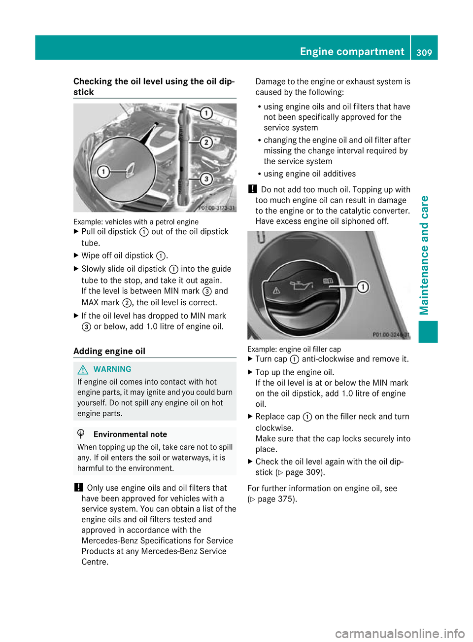
Checking the oil level using the oil dip-
stick Example
:vehicles with a petrol engine
X Pull oil dipstick :out of the oil dipstick
tube.
X Wipe off oil dipstick :.
X Slowly slide oil dipstick :into the guide
tube to the stop, and take it out again.
If the level is between MIN mark =and
MAX mark ;, the oil level is correct.
X If the oil level has dropped to MIN mark
= or below, add 1.0 litre of engine oil.
Adding engine oil G
WARNING
If engine oil comes into contact with hot
engine parts, it may ignite and you could burn
yourself. Do not spill any engine oil on hot
engine parts. H
Environmental note
When topping up the oil, take care not to spill
any. If oil enters the soil or waterways, it is
harmful to the environment.
! Only use engine oils and oil filters that
have been approved for vehicles with a
service system. You can obtain a list of the
engine oils and oil filters tested and
approved in accordance with the
Mercedes-Benz Specifications for Service
Products at any Mercedes-Benz Service
Centre. Damage to the engine or exhaust system is
caused by the following:
R
using engine oils and oil filters that have
not been specifically approved for the
service system
R changing the engine oil and oil filter after
missing the change interval required by
the service system
R using engine oil additives
! Do not add too much oil. Topping up with
too much engine oil can result in damage
to the engine or to the catalytic converter.
Have excess engine oil siphoned off. Example: engine oil filler cap
X
Turn cap :anti-clockwise and remove it.
X Top up the engine oil.
If the oil level is at or below the MIN mark
on the oil dipstick, add 1.0 litre of engine
oil.
X Replace cap :on the filler neck and turn
clockwise.
Make sure that the cap locks securely into
place.
X Check the oil level again with the oil dip-
stick (Y page 309).
For further information on engine oil, see
(Y page 375). Engine compartment
309Maintenance and care Z
Page 313 of 389
Other service products
Checking the coolant level G
WARNING
The cooling system is pressurised. Therefore,
only unscrew the cap once the engine has
cooled down. The coolant temperature gauge
must display less than 70 †.Otherwise, you
could be scalded if hot coolant escapes. X
Park the vehicle on a level surface.
Only check the coolant level if the vehicle
is on a level surface and the engine has
cooled down.
X Turn the key to position 2in the ignition
lock (Y page 159).
On vehicles with KEYLESS-GO, press the
Start/Stop button twice (Y page 159).
X Check the coolant temperature display in
the instrument cluster.
The coolant temperature must be below
70 †.
X Turn the key to position 0(Y page 159) in
the ignition lock.
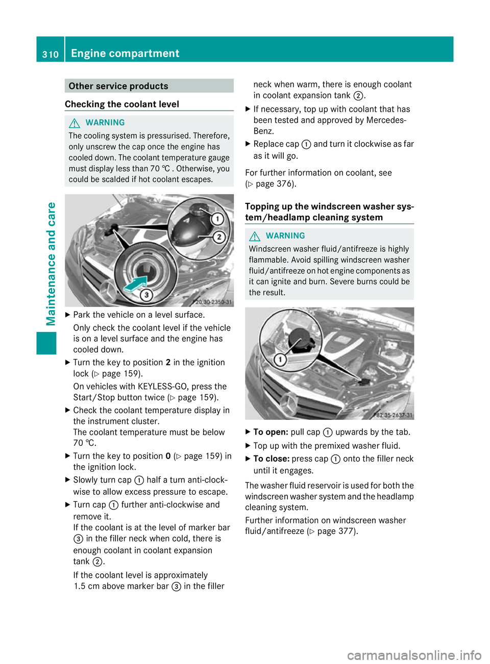
X Slowly tur ncap : half a turn anti-clock-
wise to allow excess pressure to escape.
X Turn cap :further anti-clockwise and
remove it.
If the coolant is at the level of marker bar
= in the fille rneck when cold, there is
enough coolant in coolant expansion
tank ;.
If the coolant level is approximately
1.5 cm above marker bar =in the filler neckw
hen warm, there is enough coolant
in coolant expansion tank ;.
X If necessary, top up with coolant that has
been tested and approved by Mercedes-
Benz.
X Replace cap :and turn it clockwise as far
as it will go.
For further information on coolant, see
(Y page 376).
Topping up the windscreen washer sys-
tem/headlampc leaning system G
WARNING
Windscreen washer fluid/antifreeze is highly
flammable. Avoid spilling windscreen washer
fluid/antifreeze on hot engine components as
it can ignite and burn. Severe burns could be
the result. X
To open: pull cap:upwards by the tab.
X Top up with the premixed washer fluid.
X To close: press cap :onto the filler neck
until it engages.
The washer fluid reservoir is used for both the
windscreen washer syste mand the headlamp
cleaning system.
Further informatio nonwindscreen washer
fluid/antifreeze (Y page 377).310
Engine compartmentMaintenance and care
Page 333 of 389
i
When you park the vehicle, remove the
key if you do not require any electrical con-
sumers. The vehicle will then use very little
energy, thus conserving battery power.
i After an interruption of the power supply,
e.g. the battery was discharged, you have
to:
R set the clock. Information on setting the
clock can be found in the separate oper-
ating instructions.
On vehicles with COMAND Online and a
navigation system, the clock is set auto-
matically.
R reset the function for folding the exterior
mirrors in/out automatically, by folding
the mirrors out once (Y page 118).Charging the battery
G
WARNING
Only charge the battery in a well-ventilated
area. As the battery is being charged, gases
can escape and generate minor explosions.
This could injure you and other persons or
cause damage to the paintwork or acid cor-
rosion on the vehicle.
You can obtain information on battery charg-
ers which allow the batter yto be charged
while still installed from a qualified specialist
workshop. G
WARNING
There is a risk of acid burns during the charg-
ing process due to the gases which escape
from the battery. Do not lean over the battery
during the charging process. G
WARNING
Battery acid is caustic. Avoid contact with the
skin, eyes or clothing.
! Only charge the installed battery with a
battery charger which has been tested and
approved by Mercedes-Benz. These battery chargers allow the battery to be charged
while still installed in the vehicle.
! Only use battery chargers with a maxi-
mum charging voltage of 14.8 V.
! Only charge the battery using the jump-
start connection point.
The jump-starting connection point is in the
engine compartment (Y page 331).
Read the battery charger's operating instruc-
tions before charging the battery.
X Open the bonnet (Y page 307).
X Connect the battery charger to the positive
terminal and earth point in the same order
as when connecting the donor battery in
the jump-starting procedure
(Y page 331). 330
Battery (vehicle)Breakdown assistance
Page 337 of 389
The battery must be connected and charged.
Otherwise, you:
R cannot turn the key in the ignition lock to
position 2
R cannot shift the transmission to position
N on vehicles with automatic transmission
Vehicles with automatic transmission:
release the selector lever lock manually to
move it out of position P(Y page 173).
i Deactivate the automatic locking feature
(Y page 84). You could otherwise be locked
out when pushing or towing the vehicle.
Deactivate tow-away protection
(Y page 71) before the vehicle is towed. Fitting/removing the towing eye
Fitting the towing eye G
WARNING
The exhaust tail pipe may be hot. You could
burn yourself if you touch the tail pipe. Be
particularly careful when removing the rear
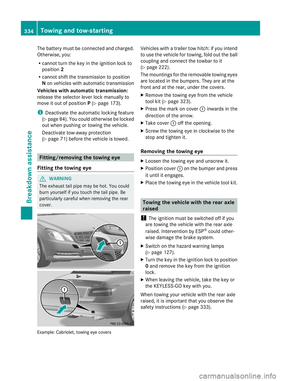
cover. Example: Cabriolet, towing eye covers Vehicles with a trailer tow hitch: if you intend
to use the vehicle for towing, fold out the ball
coupling and connect the towbar to it
(Y
page 222).
The mountings for the removable towing eyes
are located in the bumpers. They are at the
front and at the rear, under the covers.
X Remove the towing eye from the vehicle
tool kit (Y page 323).
X Press the mark on cover :inwards in the
direction of the arrow.
X Take cover :off the opening.
X Screw the towing eye in clockwise to the
stop and tighten it.
Removing the towing eye X
Loosen the towing eye and unscrew it.
X Position cover :on the bumper and press
it until it engages.
X Place the towing eye in the vehicle tool kit. Towing the vehicle with the rear axle
raised
! The ignition must be switched off if you
are towing the vehicle with the rear axle
raised. Intervention by ESP ®
could other-
wise damage the brake system.
X Switch on the hazard warning lamps
(Y page 127).
X Turn the key in the ignition lock to position
0 and remove the key from the ignition
lock.
X When leaving the vehicle, take the key or
the KEYLESS-GO key with you.
When towing your vehicle with the rear axle
raised, it is importan tthat you observe the
safety instructions (Y page 333).334
Towing and tow-startingBreakdown assistance