2012 MERCEDES-BENZ CLS SHOOTING BRAKE mirror
[x] Cancel search: mirrorPage 308 of 405
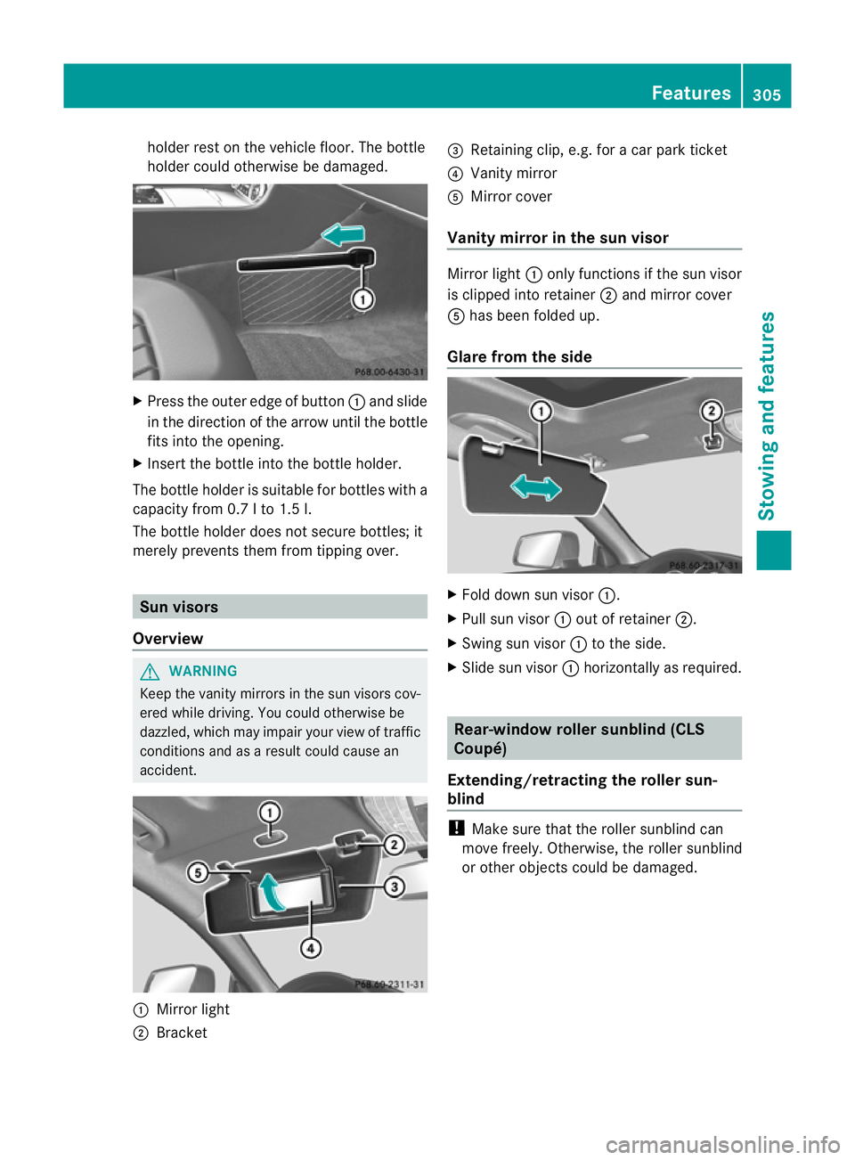
holder rest on the vehicle floor. The bottle
holder could otherwise be damaged. X
Press the outer edge of button :and slide
in the direction of the arrow until the bottle
fits into the opening.
X Insert the bottle into the bottle holder.
The bottle holder is suitable for bottles with a
capacity from 0.7 l to 1.5 l.
The bottle holder does not secure bottles; it
merely prevents them from tipping over. Sun visors
Overview G
WARNING
Keep the vanity mirrors in the sun visors cov-
ered while driving. You could otherwise be
dazzled, which may impair your view of traffic
conditions and as a result could cause an
accident. :
Mirror light
; Bracket =
Retaining clip, e.g. for a car park ticket
? Vanity mirror
A Mirror cover
Vanity mirror in the sun visor Mirror light
:only functions if the sun visor
is clipped into retainer ;and mirror cover
A has been folded up.
Glare from the side X
Fold down sun visor :.
X Pull sun visor :out of retainer ;.
X Swing sun visor :to the side.
X Slide sun visor :horizontally as required. Rear-window roller sunblind (CLS
Coupé)
Extending/retracting the roller sun-
blind !
Make sure that the roller sunblind can
move freely. Otherwise, the roller sunblind
or other objects could be damaged. Features
305Stowing and features Z
Page 314 of 405
Sliding adapter for the mobile phone
bracket Overview
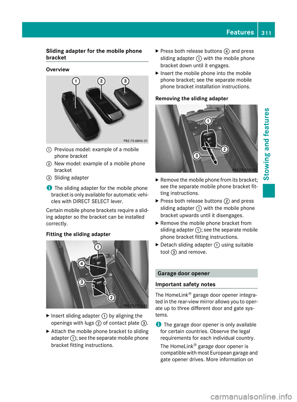
:
Previous model: example of a mobile
phone bracket
; New model: example of a mobile phone
bracket
= Sliding adapter
i The sliding adapter for the mobile phone
bracket is only available for automatic vehi-
cles with DIRECT SELECT lever.
Certain mobile phone brackets require a slid-
ing adapter so the bracket can be installed
correctly.
Fitting the sliding adapter X
Insert sliding adapter :by aligning the
openings with lugs ;of contact plate =.
X Attach the mobile phone bracket to sliding
adapter :; see the separate mobile phone
bracket fitting instructions. X
Press both release buttons ?and press
sliding adapter :with the mobile phone
bracket down until it engages.
X Insert the mobile phone into the mobile
phone bracket; see the separate mobile
phone bracket installation instructions.
Removing the sliding adapter X
Remove the mobile phone from its bracket;
see the separate mobile phone bracket fit-
ting instructions.
X Press both release buttons ;and press
sliding adapter :with the mobile phone
bracket upwards until it disengages.
X Remove the mobile phone bracket from
sliding adapter :; see the separate mobile
phone bracket fitting instructions.
X Detach sliding adapter :using suitable
tool =and remove. Garage door opener
Important safety notes The HomeLink
®
garage door opener integra-
ted in the rear-view mirror allows you to oper-
ate up to three different door and gate sys-
tems.
i The garage door opener is only available
for certain countries. Observe the legal
requirements for each individual country.
The HomeLink ®
garage door opener is
compatible with most European garage and
gate opener drives. More information on Features
311Stowing and features Z
Page 315 of 405
HomeLink
®
and/o rcompatible products is
available from:
R at a qualified specialised workshop
R the HomeLink ®
hotline
(0) 08000 466 354 65 (free of charge) or
+49 (0) 6838 907 277 (charges apply)
R on the Internet at:
http://www.homelink.com
Programming Programming buttons
G
WARNING
Only press the button on the integrated
garage door opener if there are no persons or
objects present within the sweep of the
garage door. Persons could otherwise be
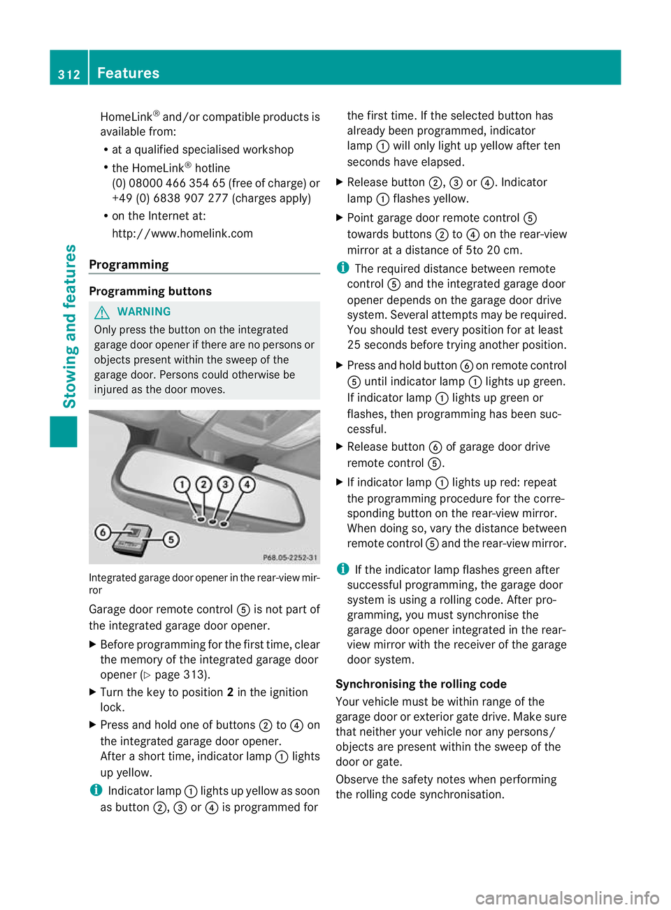
injured as the door moves. Integrated garage door opener in the rear-view mir-
ror
Garage door remote control
Ais not part of
the integrated garage door opener.
X Before programming for the first time, clear
the memory of the integrated garage door
opener (Y page 313).
X Turn the key to position 2in the ignition
lock.
X Press and hold one of buttons ;to? on
the integrated garage door opener.
After a short time, indicator lamp :lights
up yellow.
i Indicator lamp :lights up yellow as soon
as button ;,=or? is programmed for the first time. If the selected button has
already been programmed, indicator
lamp
:will only light up yellow after ten
seconds have elapsed.
X Release button ;,=or?. Indicator
lamp :flashes yellow.
X Point garage door remote control A
towards buttons ;to? on the rear-view
mirror at a distance of 5to 20 cm.
i The required distance between remote
control Aand the integrated garage door
opener depends on the garage door drive
system. Several attempt smay be required.
You should test every positio nfor at least
25 seconds before trying another position.
X Press and hold button Bon remote control
A until indicator lamp :lights up green.
If indicator lamp :lights up green or
flashes, then programming has been suc-
cessful.
X Release button Bof garage door drive
remote control A.
X If indicator lamp :lights up red: repeat
the programming procedure for the corre-
sponding button on the rear-view mirror.
When doing so, vary the distance between
remote control Aand the rear-view mirror.
i If the indicator lamp flashes green after
successful programming, the garage door
system is using a rolling code. After pro-
gramming, you must synchronise the
garage door opener integrated in the rear-
view mirror with the receiver of the garage
door system.
Synchronising the rolling code
Your vehicle must be within range of the
garage door or exterior gate drive. Make sure
that neither your vehicle nor any persons/
objects are present within the sweep of the
door or gate.
Observe the safety notes when performing
the rolling code synchronisation. 312
FeaturesStowing and features
Page 316 of 405
X
Turn the key to position 2in the ignition
lock.
X Press the programming button of the door
or gate drive (see the door or gate drive
operating instructions, e.g. under "Pro-
gramming of additional remote controls").
i Usually, you now have 30seconds to ini-
tiate the next step.
X Press previously programmed button ;,
= or? of the integrated garage door
opener until the door closes.
The rolling code synchronisation is then
complete.
Problems when programming
If you have problems when programming the
integrated garage door opener, please note
the following:
R Check the transmitter frequency of garage
door drive remote control A.This can usu-
ally be found on the back of the remote
control.
R Replace the batteries in garage door
remote control A.This increases the like-
lihood that garage door remote control A
will transmit a strong and precise signal to
the integrated garage door opener in the
rear-view mirror.
R When programming, hold remote control
A at varying distances and angles from the
button which you are programming. Try var-
ious angles at a distance between 5and
30 cm or at the same angle but at varying
distances.
R If there is another remote control for the
same garage door drive, perform the pro-
gramming steps again using this remote
control. Before performing these steps,
make sure that new batteries have been
fitted in garage door drive remote control
A.
R Note that some remote controls transmit
only for a limited period (the indicator lamp
on the remote control goes out). Press but- ton
Bon remote control Aagain before
transmission ends.
R Align the aerial cable of the garage door
opener unit. This can improve signal recep-
tion/transmission.
Opening or closing the garage door Once programmed, the integrated garage
door opener will assume the function of the
garage door system's remote control. Please
also read the operating instructions for the
garage door system.
X
Turn the key to position 2in the ignition
lock.
X Press button ;,=or? which you have
programmed to operate the garage door.
Garage door system with a fixed code: indi-
cator lamp :lights up green.
Garage door system with a rolling code:
indicator lamp :flashes green.
i The transmitter will transmit a signal for
as long as the button is pressed. The trans-
mission is halted after a maximum of ten
seconds and indicator lamp :lights up
yellow. Press button ;,=or? again if
necessary.
Clearing the memory X
Turn the key to position 2in the ignition
lock.
X Press buttons ;and ?.
The indicator lamp lights up yellow.
X Press and hold buttons ;and ?until the
indicator lamp turns green.
i Make sure that you clear the memory of
the integrated garage door opener before
selling the vehicle. Features
313Stowing and features Z
Page 331 of 405
Cleaning the windows
G
WARNING
Switch off the windscree nwipers and remove
the key fro mthe ignition lock before cleaning
the windscreen or the wiper blades. On vehi-
cles with KEYLESS-GO, press the Start/Stop
button repeatedly until all indicator lamps in
the instrument cluster have gone off. The
windscreen wipers could otherwise move and
injure you.
! Do not use dry cloths, abrasive products,
solvents or cleaning agents containing sol-
vents to clean the inside of the windows.
Do not touch the insides of the windows
with hard objects, e.g. an ice scraper or
ring. There is otherwise a risk of damaging
the windows.
! Cleant he water drainage channels of the
windscreen and the rear window at regular
intervals. Deposits such as leaves, petals
and pollen may under certain circumstan-
ces prevent water from draining away.T his
can lead to corrosion damage and damage
to electronic components.
X Cleant he inside and outside of the win-
dows with a damp cloth and a cleaning
agent that is recommended and approved
by Mercedes-Benz.
Cleaning the wiper blades G
WARNING
Switch off the windscreen wipers and remove
the key from the ignition lock before cleaning
the windscreen or the wiper blades. On vehi-
cles with KEYLESS-GO, press the Start/Stop
button repeatedly until all indicator lamps in
the instrument cluster have gone off. The
windscreen wipers could otherwise move and
injure you.
! Do not pull on the wiper blade. Otherwise,
the wiper blade could be damaged.
! Do not clean wiper blades too often and
do not rub them too hard. Otherwise, the graphite coating could be damaged. This
could cause wiper noise.
! Hold the wiper arm securely when folding
back. The windscreen could be damaged if
the wiper arm hits against it suddenly.
X Fold the wiper arms away from the wind-
screen.
X Carefully clean the wiper blades with a
damp cloth.
X Fold the windscreen wipers back again
before switching on the ignition.
Cleaning the exterior lighting !
Only use cleaning agents or cleaning
cloths that are suitable for plastic lenses.
Unsuitable cleaning agents or cleaning
cloths could scratch or damage the plastic
lenses of the exterior lighting.
X Cleant he plastic lenses of the exterior
lighting using a wet sponge and a mild
cleaning agent, e.g. Mercedes-Ben zcar
shampoo or cleaning cloths.
Mirror turn signal !
Only use cleaning agents or cleaning
cloths that are suitable for plastic lenses.
Unsuitable cleaning agents or cleaning
cloths could scratch or damage the plastic
lenses of the mirror tur nsignals.
X Clean the plasti clenses of the mirror turn
signals in the exterior mirror housing using
a wet sponge and mild cleaning agent, e.g.
Mercedes-Benzc ar shampoo or cleaning
cloths.
Cleaning the sensors !
If you clean the sensors with a high-pres-
sure cleaner, make sure that you keep a
distance of at least 30 cm between the
vehicle and the high-pressure cleane rnoz-
zle. Information about the correct distance
is available from the equipment manufac-
turer. 328
CareMaintenance and care
Page 346 of 405
On vehicles with COMAND Online and a
navigation system, the clock is set auto-
matically.
R reset the function for folding the exterior
mirrors in/out automatically, by folding
the mirrors out once (Y page 109).Charging the battery
G
WARNING
During charging and jump-starting, explosive
gases can escape from the battery. There is a
risk of an explosion.
Particularly avoid fire, naked flames, creating
sparks and smoking. Ensure there is sufficient
ventilation while charging and jump-starting.
Do not lean over a battery. G
WARNING
Battery acid is caustic. There is a risk of injury.
Avoid contact with the skin, eyes or clothing.
Do not inhale any battery gases. Do not lean
over the battery. Keep children away from
batteries. Wash battery acid immediately with
water and seek medical attention. G
WARNING
A discharged battery can freeze at tempera-
tures below freezing point. When jump-start-
ing the vehicle or charging the battery, gases
can escape from the battery. There is a risk of
an explosion.
Allow the frozen battery to thaw out before
charging it or jump-starting.
! Only use battery chargers with a maxi-
mum charging voltage of 14.8 V.
! Only charge the battery using the jump-
start connection point.
The jump-starting connection point is in the
engine compartment (Y page 344).
If, at low temperatures, the indicator lamps/
warning lamps in the instrument cluster do
not light up, it is highly likely that the dis-
charged battery has frozen. In this case, you may neither charge the battery nor jump-start
the vehicle. The service life of a thawed-out
battery may be shorter. Starting characteris-
tics are particularly impaired at low tempera-
tures. Have the thawed-out battery checked
at a qualified specialist workshop.
Never charge a battery which is still fitted in
the vehicle unless a Mercedes-Benz approved
battery charger is being used.
Abattery
charge runit specially adapted for Mercedes-
Benz vehicles and tested and approved by
Mercedes-Benz is available as an accessory.
It permits the charging of the battery in its
installed position. Contact a Mercedes-Benz
Service Centre for informatio nand availabil-
ity .R ead the battery charger's operating
instructions before chargin gthe battery.
X Open the bonnet (Y page 320).
X Connect the battery charger to the positive
terminal and earth point in the same order
as when connecting the donor battery in
the jump-starting procedure
(Y page 344). Battery (vehicle)
343Breakdown assistance Z
Page 397 of 405
At temperatures below freezing:
X
Fill the washe rfluid reservoir with a mixture
of water and washer fluid, e.g. MB Winter-
Fit.
Adapt the mixing ratio to the outside temper-
ature.
R Down to Ò10 †: mix 1 part MB WinterFit to
2 parts water.
R Down to Ò20 †: mix 1 part MB WinterFit to
1 part water.
R Down to Ò29 †: mix 2 parts MB WinterFit
to 1 part water.
i Add washer fluid concentrate, e.g. MB
SummerFit or MB WinterFit, to the washer
fluid all year round. Vehicle data
General notes
Please note that for the specified vehicle
data:
R the heights specified may vary as a result
of:
-Tyres
- Load
- Condition of the suspension
- Optional equipment
R items of optional equipmen tincrease the
unladen weight and reduce the maximum
payload. The unladen weight is specified in
accordance with EC directive and includes:
- driver (68 kg)
- luggage (7 kg)
- all fluids (fuel tank 90% full)
R vehicle-specific weight informatio ncan be
found on the vehicle identification plate
(Y page 384).
R only for certain countries :you can find vehi-
cle-specific vehicle data in the COC docu-
ments (CERTIFICATE OF CONFORMITY).
These documents are delivered with your
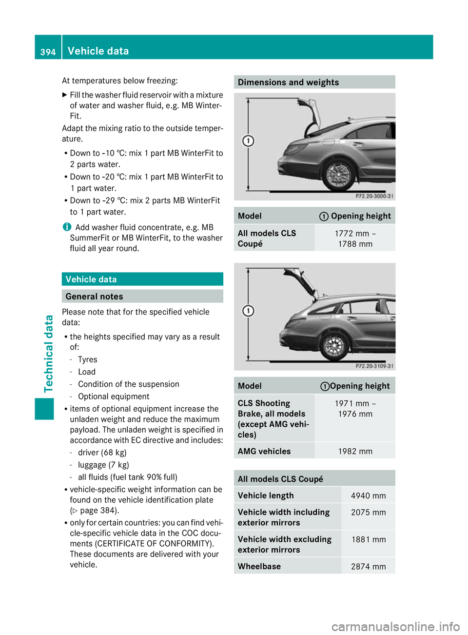
vehicle. Dimensions and weights
Model : Opening height
All models CLS
Coupé
1772 mm –
1788 mm Model : Opening height
CLS Shooting
Brake, all models
(except AMG vehi-
cles)
1971 mm –
1976 mm AMG vehicles
1982 mm
All models CLS Coupé
Vehicle length
4940 mm
Vehicle width including
exterior mirrors
2075 mm
Vehicle width excluding
exterior mirrors
1881 mm
Wheelbase
2874 mm394
Vehicle dataTechnical data
Page 398 of 405
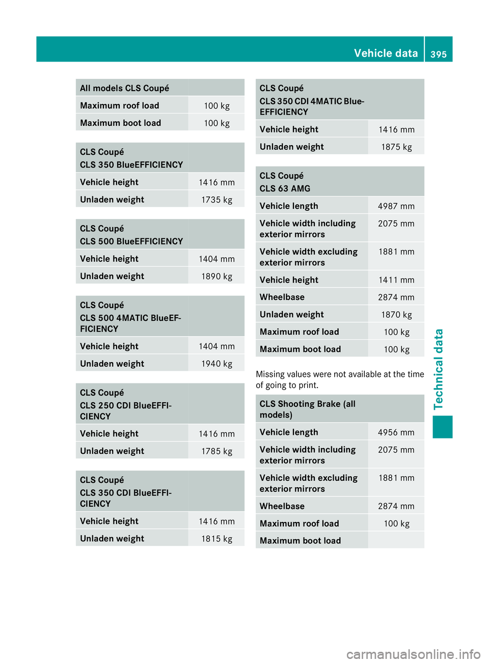
All models CLS Coupé
Maximum roof load
100 kg
Maximum boot load
100 kg
CLS Coupé
CLS 350 BlueEFFICIENCY
Vehicle height
1416 mm
Unladen weight
1735 kg
CLS Coupé
CLS 500 BlueEFFICIENCY
Vehicle height
1404 mm
Unladen weight
1890 kg
CLS Coupé
CLS 500 4MATIC BlueEF-
FICIENCY
Vehicle height
1404 mm
Unladen weight
1940 kg
CLS Coupé
CLS 250 CDI BlueEFFI-
CIENCY
Vehicle height
1416 mm
Unladen weight
1785 kg
CLS Coupé
CLS 350 CDI BlueEFFI-
CIENCY
Vehicle height
1416 mm
Unladen weight
1815 kg CLS Coupé
CLS 350 CDI 4MATIC Blue-
EFFICIENCY
Vehicle height
1416 mm
Unladen weight
1875 kg
CLS Coupé
CLS 63 AMG
Vehicle length
4987 mm
Vehicle widt
hincluding
exterior mirrors 2075 mm
Vehicle width excluding
exterior mirrors
1881 mm
Vehicle height
1411 mm
Wheelbase
2874 mm
Unladen weight
1870 kg
Maximum roof load
100 kg
Maximum boot load
100 kg
Missing values were not available at the time
of going to print.
CLS Shooting Brake (all
models)
Vehicle length
4956 mm
Vehicle width including
exterior mirrors
2075 mm
Vehicle width excluding
exterior mirrors
1881 mm
Wheelbase
2874 mm
Maximum roof load
100 kg
Maximum boot load Vehicle data
395Technical data Z