2012 MERCEDES-BENZ CLS SHOOTING BRAKE tow bar
[x] Cancel search: tow barPage 17 of 405
Luggage compartment enlarge-
ment
................................................... 294
Luggage compartment floor opening/closing ............................ 302
stowage well, unde r....................... 302
Luggage cover
Removing and fitting ......................298
Luggage holde r(EASY-PACK load-
securing kit) ...................................... .300
Lumbar support Adjusting ....................................... 104
Adjusting the 4-way lumba rsup-
por t................................................ 104
Luxu ry head restraint .......................101 M
M+S tyres ........................................... 356
Main-beam headlamps Display message ............................ 257
Switching Adaptive Highbeam
Assist on/off ................................. 121
Switching on/off ........................... 117
Massage function (PULSE) ...............103
Matt finish (cleaning instructions) ..327
Memory card (audio) .........................234
Memory function ............................... 111
Mercedes-Benz Service Centre see Qualified specialist workshop
Message memory (on-board com-
puter) ................................................. .249
Messages see Display messages
Mirror
see Vanity mirror (in sun visor)
Mirrors
see Exterior mirrors
see Rear-view mirror
Mobile phone
Frequencies ................................... 383
Installatio n..................................... 383
Menu (on-board computer) ............235
Notes/placing in the bracket ......... 309
Sliding adapter ............................... 311
Transmission output (maximum) .... 383
Modifying the programming (key) .....78
MOExtended tyres .............................337
Motorway mode ................................ 119MP3
Operating ...................................... .234
see Separate operating instructions
Multifunction display
Function/notes ............................. 229
Permanent displa y......................... 239
Multifunction steering wheel
Operating the on-board computer .228
Overview .......................................... 33 N
Navigation Menu (on-board computer) ............232
NECK-PRO head restraints
Operation ........................................ .46
Resetting after being triggered ........47
NECK-PRO luxury head restraints
Operation ........................................ .46
Resetting after being triggered ........48
Night View Assist Plus
Activating/deactivating .................206
Cleaning ......................................... 330
Function/notes ............................. 205
Problem (fault) ............................... 208
Notes on running in anew vehicle ..146 O
Occupant safety Childre ninthe vehicle ..................... 53
Important safety notes ....................40
Odometer
see Total distance recorder
see Trip meter
Oil
see Engine oil
On-board computer
AMG menu ..................................... 246
Assistance menu ........................... 236
Audi omenu ................................... 233
Convenience submenu ..................244
Displaying a service message ........324
Display messages ..........................249
DISTRONI CPLUS ........................... 183
Factory setting submenu ...............245
Heating submenu ........................... 243
Important safety notes ..................22614
Index
Page 202 of 405

Activating/deactivating the reversing
camera
X
To activate: make sure that the key is in
position 2in the ignition lock.
X Make sure that the "Activation by R gear"
setting is active in COMAND Online; see the
separate COMAND Online operating
instructions.
X Engage reverse gear.
The area behind the vehicle is shown with
guide lines in the COMAND display.
X To change the function mode for vehi-
cles with trailer tow hitch: using the
COMAND controller, select symbol :for
the "Reverse parking" function or sym-
bol ;for "Coupling up a trailer" (see the
separate COMAND Online operating
instructions).
The symbol of the selected function is high-
lighted.
To deactivate: the reversing camera is deac-
tivated if you:
R shif tthe transmission to position P
R drive forwards 10 m
R shift the transmission from Rto another
position (after 15 seconds)
R drive forwards at a speed of over
10 km/h Displays in the COMAND display G
WARNING
Using the reversing camera can be dangerous
if you are colour-blind or if your ability to dis-
tinguish colours is impaired.
Only use the reversing camera if you can see
and distinguish between all the coloured
guide lines that are displayed by the reversing
camera in the COMAND display. G
WARNING
Please note that objects not at ground level
may appear to be further away than they
actually are. These include:
R the bumper of a vehicle that is parked
behind your vehicle
R a trailer drawbar
R the ball coupling of a trailer tow hitch
R the tail-end of a lorry
R slanted posts
The lines are only guides, not accurate meas-
urements of the distance to an obstacle.
Therefore, you should never pass the red line
when approaching an obstacle. You could oth-
erwise cause an accident and injure yourself
and others. :
White guide line without turning the steer-
ing wheel, vehicle width including the
exterior mirrors (static)
; Yellow guide line at a distance of approx-
imately 4.0 mfrom the rear of the vehicle Driving systems
199Driving and parking Z
Page 205 of 405
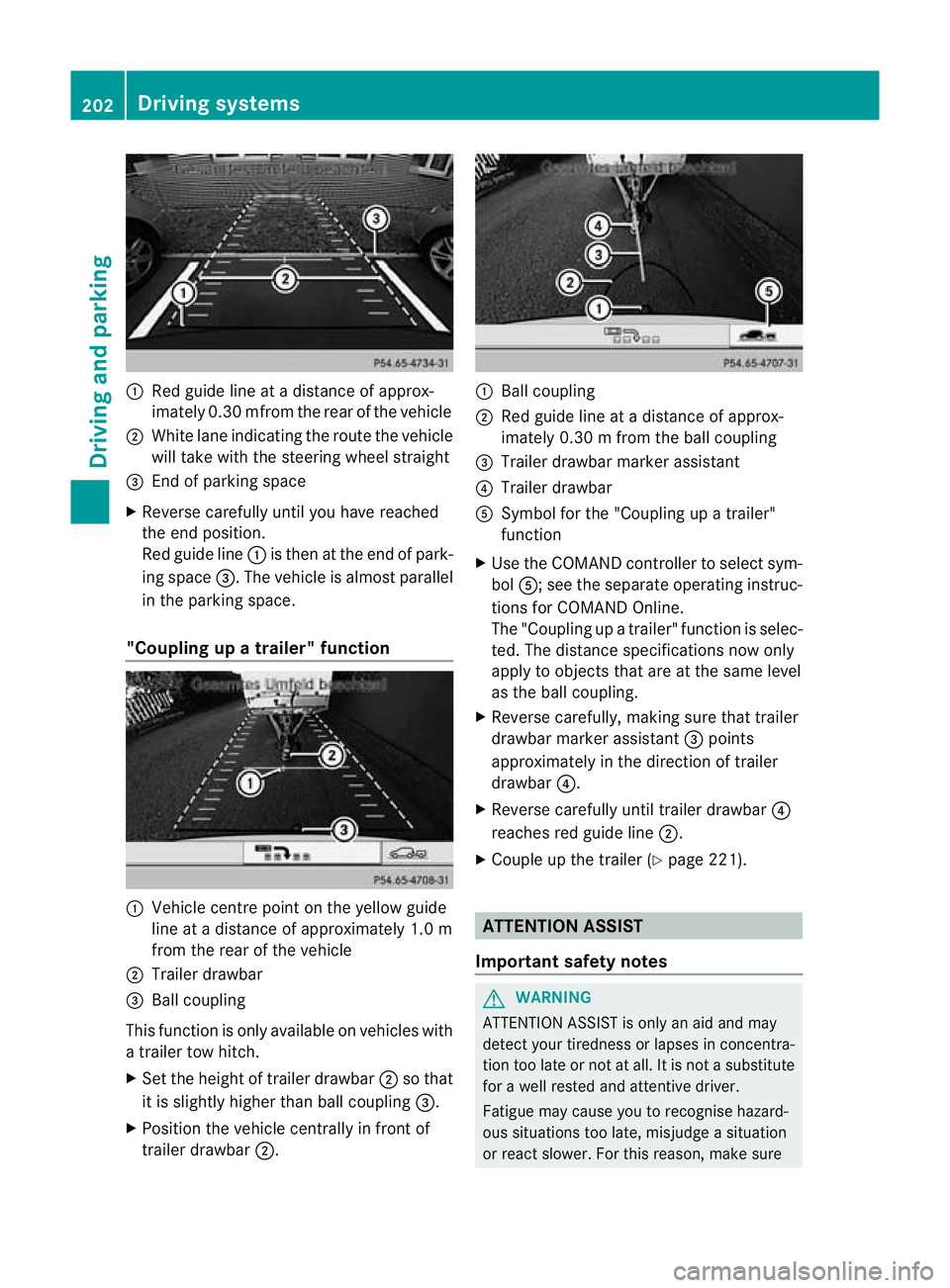
:
Red guide line at a distanc eofapprox-
imately 0.3 0mfrom the rear of the vehicle
; White lane indicating the route the vehicle
will take with the steering wheel straight
= End of parking space
X Reverse carefully until you have reached
the end position.
Red guide line :is then at the end of park-
ing space =.The vehicle is almost parallel
in the parking space.
"Coupling up a trailer" function :
Vehicle centre point on the yellow guide
line at a distance of approximately 1.0 m
from the rear of the vehicle
; Trailer drawbar
= Ball coupling
This function is only available on vehicles with
a trailer tow hitch.
X Set the height of trailer drawbar ;so that
it is slightly higher than ball coupling =.
X Position the vehicle centrally in front of
trailer drawbar ;. :
Ball coupling
; Red guide line at a distance of approx-
imately 0.30 m from the ball coupling
= Trailer drawbarm arker assistant
? Trailer drawbar
A Symbol for the "Coupling up a trailer"
function
X Use the COMAND controller to selec tsym-
bol A; see the separate operating instruc-
tions for COMAND Online.
The "Coupling up a trailer "function is selec-
ted. The distance specifications now only
apply to objects that are at the same level
as the ball coupling.
X Reverse carefully, making sure that trailer
drawbar marke rassistant =points
approximately in the direction of trailer
drawbar ?.
X Reverse carefully until trailer drawbar ?
reaches red guide line ;.
X Couple up the trailer (Y page 221). ATTENTION ASSIST
Important safety notes G
WARNING
ATTENTION ASSIST is only an aid and may
detect your tiredness or lapses in concentra-
tion too late or not at all. It is not asubstitute
for a well rested and attentive driver.
Fatigue may cause you to recognise hazard-
ous situations too late, misjudge a situation
or react slower. For this reason, make sure 202
Driving systemsDriving and pa
rking
Page 221 of 405
Never use the brake pedal as a footrest. Do
not simultaneously depress both the brake
pedal and the accelerator pedal while driving. G
WARNING
You could lose control of the vehicle/trailer
combination if it begins to swerve. The vehi-
cle/trailer combination could even overturn.
There is a risk of an accident.
On no account should you attempt to
straighten out the vehicle/trailer combina-
tion by increasing speed. Decrease your
speed and do not countersteer. Brake if nec-
essary. G
WARNING
If you exceed the permissible noseweight
while carrying a load, the carrier system could
detach from the vehicle and fall on the road.
There is a risk of an accident and injury.
Always maintain the permissible noseweight
when carrying loads. G
WARNING
If the ball coupling is not correctly engaged, it
could detach while driving and fall on the road.
There is a risk of an accident and injury.
Engage the ball coupling as described. G
WARNING
If the ball coupling is not correctly engaged,
the trailer can detach. There is a risk of an
accident.
Always engage the ball coupling as described.
! Depressing the brake pedal constantly
results in excessive and premature wearto
the brake pads.
You can use carrier systems, e.g .bicycle
racks or load-bearing implements, on the ball
coupling. The maximum noseweight of
75 kg applies when using carrier systems on
the ball coupling.
When reversing the vehicle towards the
trailer, make sure there is nobody between
the trailer and the vehicle. Couple and uncouple the trailer carefully. If
you do not couple the trailer to the towing
vehicle correctly, the trailer could become
detached.
Make sure that the followin gvalues are not
exceeded:
R the permissible trailer drawbar noseweight
R the permissible trailer load
R the permissible rear axle load of the towing
vehicle
R the maximum permissible gross vehicle
weigh tofboth the towing vehicle and the
trailer
You will find the applicable permissible val-
ues, which must not be exceeded, in the vehi-
cle documents.
You will find the values approved by the man-
ufacturer on the vehicle identification plates
and those for the towing vehicle in the "Tech-
nical data" section (Y page 398).
When towing a trailer, your vehicle's handling
characteristics will be different in comparison
to when driving without a trailer.
The vehicle/trailer combination:
R is heavier
R is restricted in its acceleration and gradi-
ent-climbing capability
R has an increased braking distance
R is affected more by strong crosswinds
R demands more sensitive steering
R has a larger turning circle
This could impair the handling characteris-
tics. Adapt your style of driving accordingly.
Maintain a safe distance. Drive carefully.
When towing a trailer, always adjust your
speed to the current road and weather con-
ditions. Do not exceed the maximum permis-
sible speed for your vehicle/trailer combina-
tion. 218
Towing
atrailerDriving an d parking
Page 222 of 405
Notes on towing
atrailer
General notes !
Use a drawbar noseweigh tas close as
possible to the maximum permissible nose-
weight. Do not use a noseweight of less
than 50kg, otherwise the trailer may come
loose.
Note that the payload and the rear axle load
are reduced by the actual payload.
i When towing a trailer, set the tyre pres-
sure on the rear axle of the towing vehicle
for a maximum load; see the tyre pressure
table in the fuel filler flap (Y page 357).
You will find installation dimensions and loads
in the "Technical data" section
(Y page 396).
The maximum noseweight of the trailer draw-
bar on the ball coupling is 84 kg. The actual
noseweight may however not be higher than
the value which is given on the trailer tow
hitch or trailer identification plates. The low-
est weight applies.
Please note that when towing a trailer, PARK-
TRONIC (Y page 191), Active Parking Assist
(Y page 194) and Blind Spot Assist
(Y page 208) are only available with limita-
tions, or not at all.
i On vehicles without level control, the
height of the ball coupling will alter accord-
ing to the load placed on the vehicle. If nec-
essary, use a trailer with a height-adjusta-
ble drawbar.
Driving tips i
Observe the notes on ESP ®
trailer stabi-
lisation (Y page 69).
The maximum permissible speed for vehicle/
trailer combinations depends on the type of
trailer. Before beginning the journey, check
the trailer's documents to see what the max-
imum permitted speed is. Observe the legally
prescribed maximum speed in the relevant
country. For certain Mercedes-Benz vehicles, the max-
imum permissible rear axle load is increased
when towing a trailer. Refer to the "Technical
data" section to find out whether this applies
to your vehicle. If you utilise any of the added
maximum rear axle load when towing a trailer,
the vehicle/trailer combination may not
exceed a maximum speed of 100 km/h for
reasons concerning the operating permit.
This also applies in countries in which the
permissible maximum speed for vehicle/
trailer combinations is above 100 km/h.
When towing a trailer, your vehicle's handling
characteristics will be different in comparison
to when driving without a trailer and it will
consume more fuel.
Change into a lower gear in good time on long
and steep downhill gradients.
On long and steep downhill gradients, espe-
cially if the vehicle is laden or towing a trailer,
you must select shift range 1,2or 3.
i This also applies if you have activated
cruise control, SPEEDTRONIC or DIS-
TRONIC PLUS.
This will use the braking effect of the engine,
so less braking will be required to prevent the
vehicle from gaining speed. This relieves the
load on the brake system and prevents the
brakes from overheating and wearing too
quickly. If you need additional braking,
depress the brake pedal repeatedly rather
than continuously.
Driving tips If the trailer swings from side to side:
X
Do not accelerate.
X Do not countersteer.
X Brake if necessary. Towing
atrailer
219Driving an d parking Z
Page 224 of 405
The multifunction display shows the
Check trailer hitch lock
message
until the ball coupling is engaged.
X Remove the protective covering from the
ball coupling and store it in a safe place.
X Make sure that the ball of the ball coupling
is clean and greased.
The power socket is integrated in the ball
coupling. Coupling up a trailer
G
WARNING
If you uncouple a trailer with an engaged over-
run brake, you could trap your hand between
the vehicle and the trailer drawbar. This poses
a risk of injury.
Do not uncouple a trailer with an engaged
overrun brake.
X Make sure that the transmission is in posi-
tion P.
X Apply the parking brake.
X Position the trailer level behind the vehicle.
X Couple up the trailer.
X Establish the electrical connection
between the vehicle and the trailer.
X Check that the trailer lighting system is
working. Uncoupling
atrailer G
WARNING
If you uncouple a trailer with an engaged over-
ru nb rake, you could trap yourh and between
the vehicle and the trailer drawbar .This poses
a risk of injury.
Do not uncouple a trailer with an engaged
overrun brake. G
WARNING
Vehicles with level control: If you disconnectt
he trailer cable, the vehicle
is lowered. This can cause you or others to
become trapped between the vehicle body
and tyres, or underneath the vehicle. This
poses a risk of injury.
Make sure that no-one is in the immediate
vicinity of the wheel arch or underneath the
vehicle when disconnecting the trailer cable.
! Do not disconnect a trailer with an
engaged overrun brake. Otherwise, your
vehicle could be damaged by the rebound-
ing of the overrun brake.
X Make sure that the transmission is in posi-
tion P.
X Apply the parking brake.
X Secure the trailer against rolling away.
X Remove the trailer cable and decouple the
trailer. Folding in the ball coupling
G
WARNING
If you release the ball coupling or it does not
engage correctly when folding in, it will swing
out. Within pivoting range of the ball coupling,
there is an increased risk of an accident and
injury.
Only release the ball coupling if the pivoting
range is unobstructed. Always make sure that
the ball coupling engages when folding in.
X Place the protective covering on the ball
coupling. Towing
atrailer
221Driving an d parking Z
Page 319 of 405
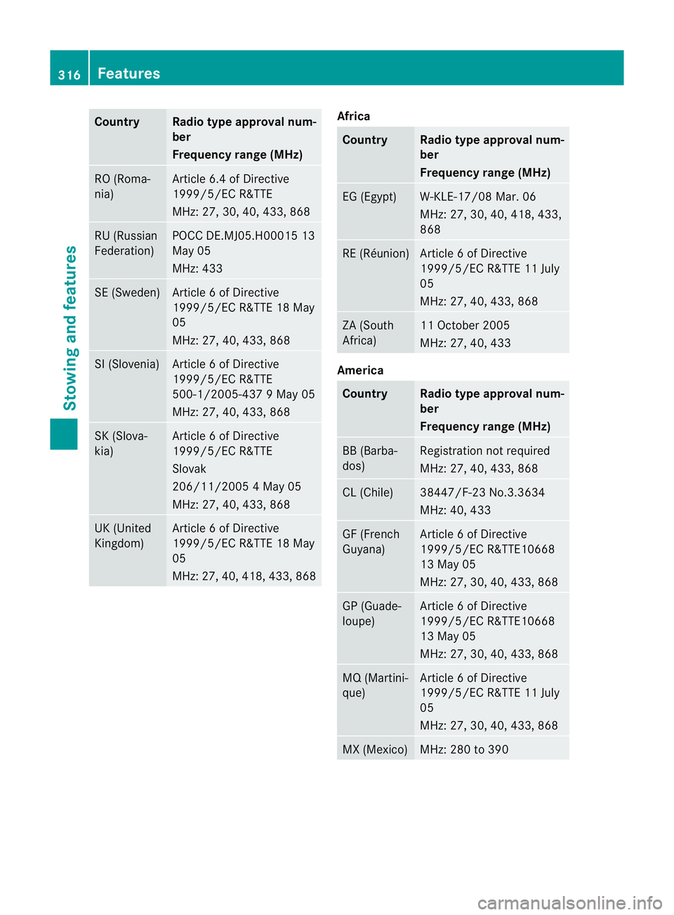
Country Radio type approval num-
ber
Frequency range (MHz)
RO (Roma-
nia) Article 6.4 of Directive
1999/5/EC R&TTE
MHz: 27, 30, 40
,433, 868 RU (Russian
Federation) POCC DE.MJ05.H00015 13
May 05
MHz: 433
SE (Sweden) Article 6 of Directive
1999/5/EC R&TTE 18 May
05
MHz: 27, 40, 433, 868
SI (Slovenia) Article 6 of Directive
1999/5/EC R&TTE
500-1/2005-437 9 May 05
MHz: 27, 40, 433, 868
SK (Slova-
kia) Article 6 of Directive
1999/5/EC R&TTE
Slovak
206/11/2005 4 May 05
MHz: 27, 40, 433, 868
UK (United
Kingdom) Article 6 of Directive
1999/5/EC R&TTE 18 May
05
MHz: 27, 40, 418, 433, 868 Africa
Country Radio type approval num-
ber
Frequency range (MHz)
EG (Egypt) W-KLE-17/08 Mar. 06
MHz: 27, 30, 40, 418, 433,
868
RE (Réunion) Article 6 of Directive
1999/5/EC R&TTE 11 July
05
MHz: 27, 40, 433, 868
ZA (South
Africa) 11 October 2005
MHz: 27, 40, 433
America
Country Radio type approval num-
ber
Frequency range (MHz)
BB (Barba-
dos) Registration not required
MHz: 27, 40, 433, 868
CL (Chile) 38447/F-23 No.3.3634
MHz: 40, 433
GF (French
Guyana) Article 6 of Directive
1999/5/EC R&TTE10668
13 May 05
MHz: 27, 30, 40, 433, 868
GP (Guade-
loupe) Article 6 of Directive
1999/5/EC R&TTE10668
13 May 05
MHz: 27, 30, 40, 433, 868
MQ (Martini-
que) Article 6 of Directive
1999/5/EC R&TTE 11 July
05
MHz: 27, 30, 40, 433, 868
MX (Mexico) MHz: 280 to 390316
FeaturesStowing and features
Page 343 of 405
!
After use, excess tyre sealant may run out
of the filler hose. This could cause stains.
Therefore, place the filler hose in the plastic
bag which contained the TIREFIT kit. H
Environmental note
Have the used tyre sealant bottle disposed of
professionally, e.g. at aqualified specialist
workshop.
If a tyre pressure of 18 0kPa (1.8 bar/26 psi)
has been attained after five minutes:
X Switch off the tyre inflation compressor.
X Unscrew the filler hose from the valve of
the faulty tyre.
X Stow the tyre sealant bottle, the tyre infla-
tion compressor and the warning triangle.
X Pull away immediately.
The maximum speed for a tyre sealed with
tyre sealant is 80 km/h. The upper part of
the TIREFIT sticker must be affixed to the
instrument cluster in the driver's field of
vision.
X Stop after driving for approximately ten
minutes and check the tyre pressure with
the tyre inflation compressor.
The tyre pressure must now be at least
130 kPa (1.3 bar/19 psi). G
WARNING
If the required tyre pressure is not reached
after driving for a short period, the tyre is too
badly damaged. The tyre sealant cannot
repair the tyre in this instance. Damaged tyres
and a tyre pressure that is too low can signif-
icantly impair the vehicle's braking and driv-
ing characteristics .There is a risk of accident.
Do not continue driving. Contact a qualified
specialist workshop.
X Correct the tyre pressure if it is still at least
130 kPa (1.3 bar/19 psi) (see the fuel filler
flap for values).
X To increase the tyre pressure: switch on
the tyre inflation compressor. X
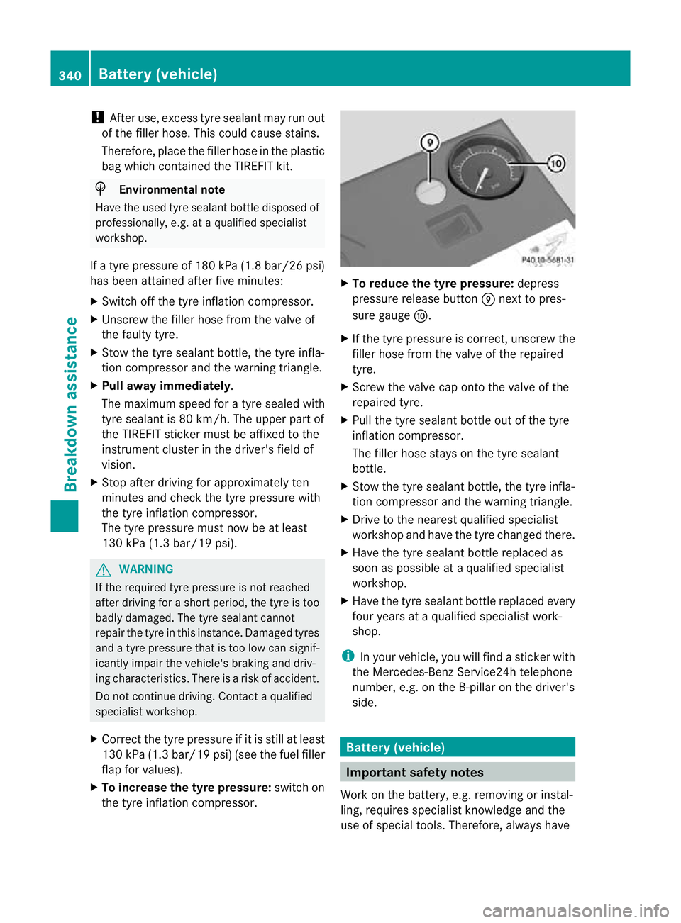
To reduce the tyre pressure: depress
pressure release button Enext to pres-
sure gauge F.
X If the tyre pressure is correct, unscrew the
filler hose from the valve of the repaired
tyre.
X Screw the valve cap onto the valve of the
repaired tyre.
X Pull the tyre sealant bottle out of the tyre
inflation compressor.
The filler hose stays on the tyre sealant
bottle.
X Stow the tyre sealant bottle, the tyre infla-
tion compressor and the warning triangle.
X Drive to the nearest qualified specialist
workshop and have the tyre changed there.
X Have the tyre sealant bottle replaced as
soon as possible at a qualified specialist
workshop.
X Have the tyre sealant bottle replaced every
four years at a qualified specialist work-
shop.
i In your vehicle, you will find a sticker with
the Mercedes-Ben zService24h telephone
number, e.g. on the B-pillar on the driver's
side. Battery (vehicle)
Important safety notes
Work on the battery, e.g. removing or instal-
ling, requires specialist knowledge and the
use of special tools. Therefore, always have 340
Battery (vehicle)Breakdown assistance