2012 MERCEDES-BENZ CLS COUPE boot
[x] Cancel search: bootPage 313 of 373
Useful information
i This Owner's Manual describes all mod-
els, series and optional equipment for your
vehicle that were available at the time of
going to press. National variation sare pos-
sible. Not ethat your vehicle may not be
equipped with all of the function sdescri-
bed. This is also the case for system sand
function srelevan ttosafety.
i Read the information on qualified special-
ist workshops: (Y page 23). Wher
ewillIfind...? Warning triangle
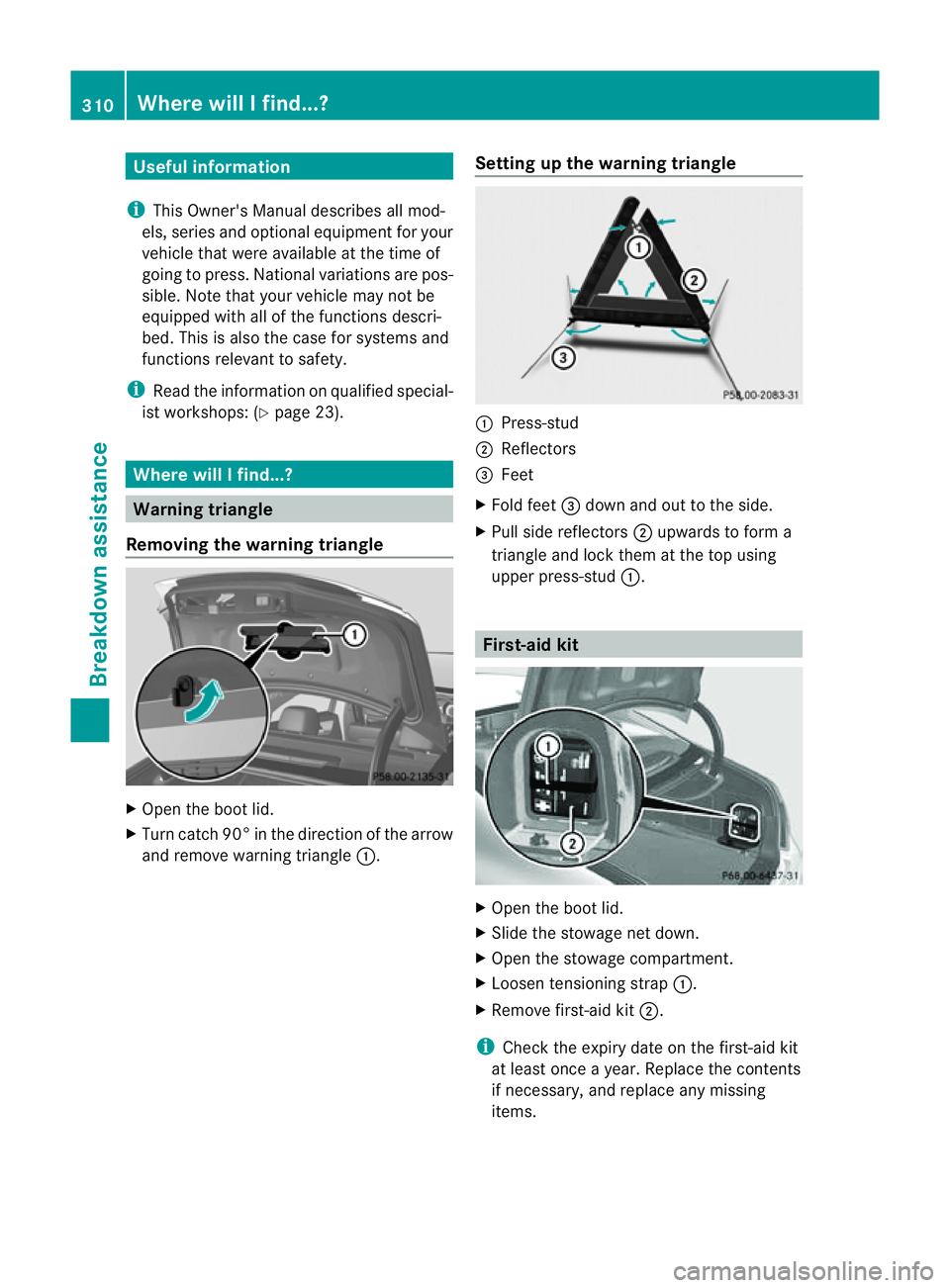
Removing the warning triangle X
Open the boot lid.
X Turn catc h90° in the direction of the arrow
and remove warning triangle :.Settin
gupthe warning triangle :
Press-stud
; Reflectors
= Feet
X Fold feet =dow nand ou ttothe side.
X Pull side reflectors ;upwards to form a
triangle and lock them at the top using
upper press-stud :. First-aid kit
X
Open the boot lid.
X Slide the stowage net down.
X Open the stowage compartment.
X Loosen tensioning strap :.
X Remove first-aid kit ;.
i Check the expiry date on the first-aid kit
at least once ayear. Replace the contents
if necessary, and replace any missing
items. 310
Where will
Ifind...?Breakdown assistance
Page 314 of 373
Fir
ee xtinguisher
! Kee pthe stowage compartmen tclosed
while the vehicle is in motion. It may oth-
erwise be damaged.
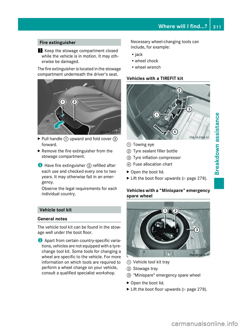
The fire extinguisher is located in the stowage
compartmen tunderneat hthe driver's seat. X
Pull handle :upward and fold cover ;
forward.
X Remove the fire extinguisher fro mthe
stowage compartment.
i Have fire extinguisher ;refilled after
each use and checked every one to two
years. It may otherwise fail in an emer-
gency.
Observe the legal requirements for each
individualc ountry. Vehicle tool kit
General notes The vehicle tool kit can be found in the stow-
age well under the boot floor.
i Apart from certain country-specific varia-
tions, vehicles are not equipped with atyre-
change tool kit. Some tools for changing a
wheel are specific to the vehicle. For more
information on which tools are required to
perform awheel change on your vehicle,
consult aqualified specialist workshop. Necessary wheel-changing tools can
include, for example:
R
jack
R wheel chock
R wheel wrench
Vehicles with aTIREFIT kit :
Towin geye
; Tyre sealan tfiller bottle
= Tyre inflation compressor
? Fuse allocation chart
X Open the boot lid.
X Lift the boot floor upwards ( Ypage 278).
Vehicles with a"Minispare" emergency
spare wheel :
Vehicle tool kit tray
; Stowag etray
= "Minispare" emergency spare wheel
X Open the boot lid.
X Lift the boot floor upwards (Y page278). Where will
Ifind...?
311Breakdown assistance
Page 315 of 373
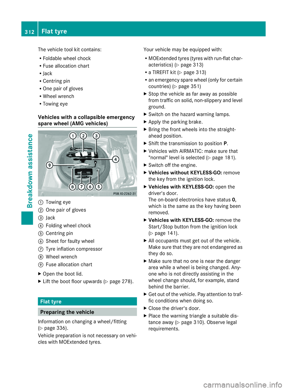
The vehicle tool kit contains:
R
Foldable wheel chock
R Fuse allocation chart
R Jack
R Centrin gpin
R One pair of gloves
R Wheel wrench
R Towing eye
Vehicles with acollapsible emergency
spare wheel (AMG vehicles) :
Towin geye
; Onep air of gloves
= Jack
? Folding wheel chock
A Centrin gpin
B Sheet for fault ywheel
C Tyre inflatio ncompressor
D Wheel wrench
E Fuse allocation chart
X Open the boot lid.
X Lift the boot floor upwards (Y page 278).Flat tyre
Preparing the vehicle
Information on changing awheel/fitting
(Y page 336).
Vehicle preparation is not necessary on vehi-
cles with MOExtended tyres. Your vehicle may be equipped with:
R
MOExtended tyres (tyres with run-flat char-
acteristics) (Y page 313)
R aT IREFIT kit (Y page 313)
R an emergenc yspare wheel (only for certain
countries) (Y page 351)
X Stop the vehicle as far away as possible
from traffic on solid, non-slippery and level
ground.
X Switch on the hazard warning lamps.
X Apply the parking brake.
X Bring the front wheels into the straight-
ahead position.
X Shift the transmission to position P.
X Vehicles with AIRMATIC: make sure that
"normal" level is selected (Y page 181).
X Switch off the engine.
X Vehicles without KEYLESS-GO: remove
the key from the ignition lock.
X Vehicles with KEYLESS-GO: open the
driver's door.
The on-board electronics have status 0,
which is the same as the key having been
removed.
X Vehicles with KEYLESS-GO: remove the
Start/Stop button from the ignition lock
(Y page 141).
X All occupant smust get out of the vehicle.
Make sure that they are not endangered as
they do so.
X Make sure that no one is near the danger
area while awheel is being changed. Any-
one who is not directly assisting in the
wheel change should, for example, stand
behind the barrier.
X Get out of the vehicle. Pay attention to traf-
fic conditions when doing so.
X Close the driver's door.
X Place the warning triangle asuitable dis-
tancea way (Y page 310). Observe legal
requirements. 312
Flat tyreBreakdown assistance
Page 317 of 373
If you come into contact with the tyre sealant,
observe the following:
R Rinse off the tyre sealant from yours kin
immediately with water.
R If the tyre sealant comes into contact with
youre yes, immediately rinse them thor-
oughly wit hclean water.
R If tyr esealant is swallowed ,immediately
rinse your mout hout thoroughl yand drink
plenty of water. Do no tind ucev omiting,
and see kmedical attention immediately.
R Immediately change out of clothing which
has come into contact with tyre sealant.
R If an allergic reaction occurs ,seek medical
attention immediately.
! Do not operate the tyre inflation com-
pressor for longer than eight minutes at a
time without abreak. It may otherwise
overheat.
The tyre inflation compressor can be oper-
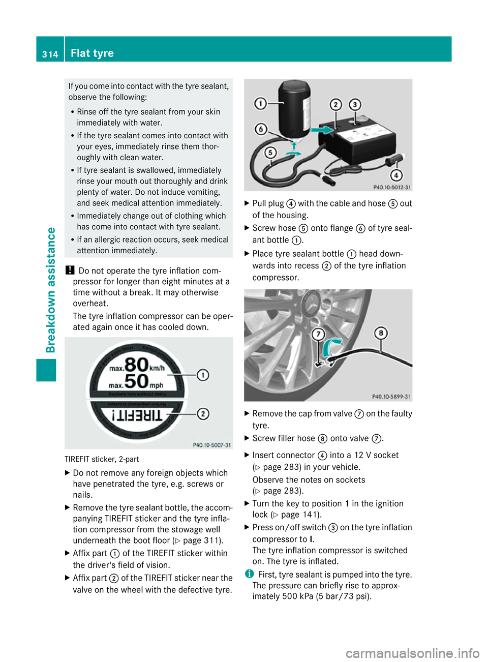
ated again onceith as cooled down.TIREFI
Tsticker, 2-part
X Do not remove any foreign objects which
have penetrated the tyre, e.g. screws or
nails.
X Remove the tyre sealant bottle, the accom-
panying TIREFI Tsticker and the tyre infla-
tion compressor from the stowage well
underneath the boot floor (Y page 311).
X Affix part :of the TIREFI Tsticker within
the driver's field of vision.
X Affix part ;of the TIREFI Tsticke rnearthe
valv eont he whee lwitht he defectiv etyre. X
Pull plug ?with the cable and hose Aout
of the housing.
X Scre whose Aonto flange Bof tyr eseal-
ant bottle :.
X Place tyr esealan tbottle : head down-
wards into recess ;of the tyr einflation
compressor. X
Remov ethe cap fro mvalve Con th efaulty
tyre.
X Screw fille rhose Dontov alveC.
X Insert connector ?into a12V socket
(Y page 283) in your vehicle.
Observe the notes on sockets
(Y page 283).
X Turn the key to position 1in the ignition
lock (Y page 141).
X Press on/offs witch=on th etyrei nflation
compressor to I.
The tyr einflatio ncompressor is switched
on. The tyre is inflated.
i First,t yre sealant is pumped into the tyre.
The pressure can briefly rise to approx-
imately 500 kPa (5 bar/73 psi). 314
Flat tyreBreakdown assistance
Page 327 of 373
You can fin
dinformation on "Jump-starting"
at (Y page 319). Electrical fuses
Important safet
ynotes G
WARNING
Only use fuses that have been approved for
Mercedes-Ben zvehicles and which have the
correct fuse ratin gfor the systems con-
cerned. Do not attempt to repair or bridge
faulty fuses. Using fuses which have not been
approved or attempting to repair or bridge
faulty fuses could cause the fuse to be over-
loaded and result in afire. Have the cause
traced and rectified at aqualified specialist
workshop.
! Only use fuses that have been approved
for Mercedes-Benz vehicles and which
have the correct fuse ratin gfor the system
concerned. Otherwise, componentsors ys-
tems could be damaged.
The fuses in your vehicle serve to close down
faulty circuits. If afuse blows ,all th ecom po-
nent sont hecircuit and their function sstop
operating.
Blown fuse smust be replace dwith fuses of
the same rating, which you can recognise by
the colour and fuse rating. The fuse ratings
are listed in the fuse allocation chart.
If the newly inserted fuse also blows, have the
cause traced and rectified at aqualified spe-
cialist workshop, e.g. aMercedes-Benz
Servic eCentre. Befor
ereplacing afuse
X Secure the vehicle against rollin gaway
(Y page 159).
X Switch off all electrical consumers. X
Turn the key to position 0in the ignition
lock and remove it (Y page 141).
or
X On vehicles with KEYLESS-GO, make sure
the ignition is switched off (Y page 141).
All indicator lamps in the instrumen tcluster
must be off.
The fuses are located in various fuse boxes:
R fuse box in the engine compartmen tonthe
left-hand side of the vehicle, when viewed
in the direction of travel
R fuse box in the boot on the right-hand side
of the vehicle, when viewed in the direction
of travel
the fuse allocation chart is located in the vehi-
cle tool kit in the stowage compartment
under the boot floor (Y page 311). Fuse box in the engine compartment
G
WARNING
Make sure that the windscreen wipers are
turned off and the key is pulledo ut of the igni-
tion lock before you open the cover of the fuse
box. Otherwise, the windscreen wipers and
the wiper rods above the cover could be set
in motion. This could lead to you or others
being injured by the wiper rods.
! Make sure that no moisture can enter the
fuse box when the cover is open.
! When closing the cover, make sure that it
is lying correctly on the fuse box. Moisture
seeping in or dirt could otherwise impair
the operation of the fuses.
X Make sure that the windscreen wipers are
switched off.
X Open the bonnet. 324
Electrical fusesBreakdown assistance
Page 328 of 373
X
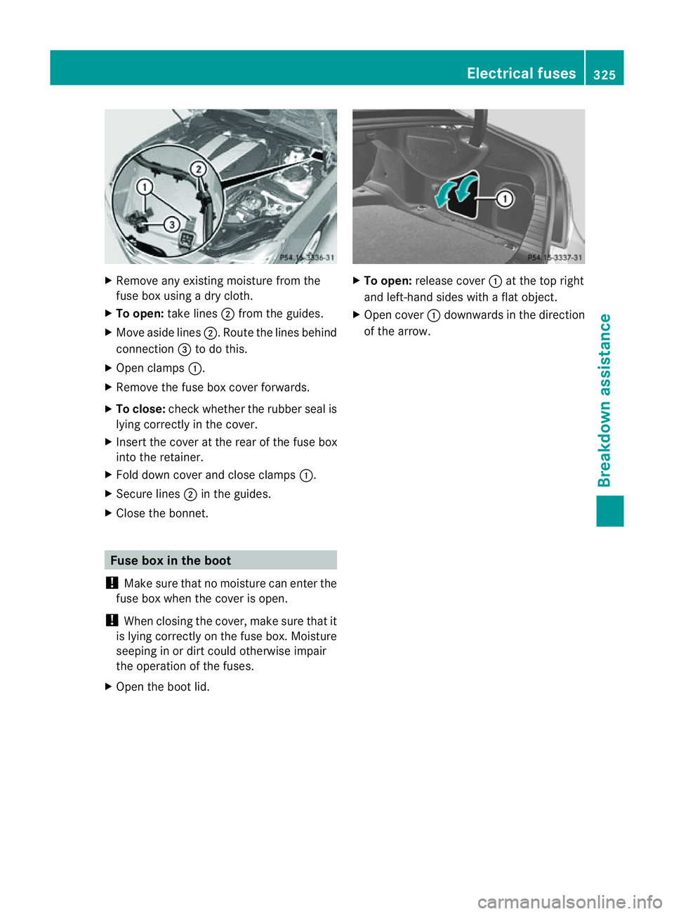
Remove any existin gmoisture from the
fus eb ox usin gadry cloth.
X To open: takelines ;from th eguides.
X Mov easide lines ;.Route the lines behind
connection =to do this.
X Open clamps :.
X Remove the fuse box cover forwards.
X To close: check whether the rubber seal is
lying correctly in the cover.
X Insert the cover at the rear of the fuse box
into the retainer.
X Fold down cover and close clamps :.
X Secure lines ;in the guides.
X Close the bonnet. Fuse box in the boot
! Make sure that no moisture can enter the
fuse box when the cover is open.
! When closing the cover, make sure that it
is lying correctly on the fuse box. Moisture
seeping in or dirt could otherwise impair
the operation of the fuses.
X Open the boot lid. X
To open: release cover :at the top right
and left-hand sides with aflat object.
X Open cover :downwards in the direction
of the arrow. Electrical fuses
325Breakdown assistance Z
Page 341 of 373
Securing the vehicle on level ground
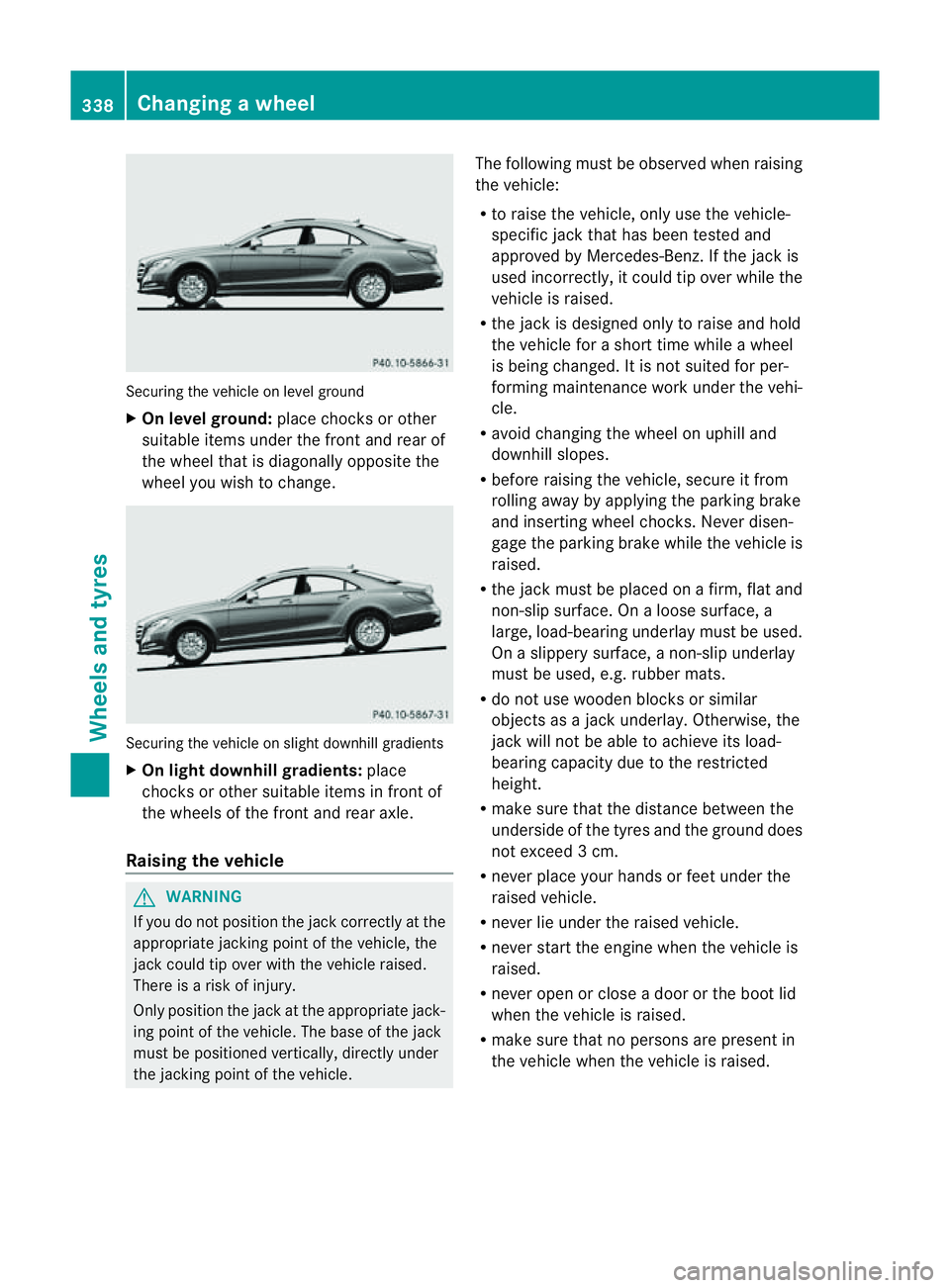
X
On level ground: place chocks or other
suitabl eitem sunder the front and rea rof
the whee ltha tisd iagonally opposite the
wheel you wish to change. Securing the vehicle on slight downhill gradients
X
On light downhill gradients: place
chocks or other suitablei tems in front of
the wheels of the front and rear axle.
Raising the vehicle G
WARNING
If you do not position the jack correctly at the
appropriate jacking point of the vehicle, the
jack could tip over with the vehicle raised.
There is arisk of injury.
Only position the jack at the appropriate jack-
ing point of the vehicle. The base of the jack
must be positioned vertically, directly under
the jacking point of the vehicle. The following must be observed when raising
the vehicle:
R
to raise the vehicle, only use the vehicle-
specific jack that has been tested and
approved by Mercedes-Benz.Ift he jack is
used incorrectly, it could tip over while the
vehicle is raised.
R the jack is designed only to raise and hold
the vehicle for ashort time while awheel
is being changed. It is not suited for per-
forming maintenance work under the vehi-
cle.
R avoid changing the wheel on uphilla nd
downhill slopes.
R before raising the vehicle, secure it from
rolling awaybya pplying the parking brake
and inserting wheel chocks. Never disen-
gage the parking brake while the vehicle is
raised.
R the jack must be placed on afirm, flat and
non-slip surface. On aloose surface, a
large, load-bearing underlay must be used.
On aslippery surface, anon-slip underlay
must be used, e.g. rubber mats.
R do not use wooden blocks or similar
objects as ajack underlay.O therwise, the
jack will no tbea ble to achiev eits load-
bearin gcapacity due to the restricted
height.
R mak esure that the distanc ebetween the
underside of the tyre sand the groun ddoes
not exceed 3cm.
R never place your hands or feet under the
raised vehicle.
R never lie under the raised vehicle.
R never start the engine when the vehicle is
raised.
R never open or clos eadoor or the boot lid
when the vehicle is raised.
R mak esure that no persons are present in
the vehicle when the vehicle is raised. 338
Changin
gawheelWheels and tyres
Page 344 of 373
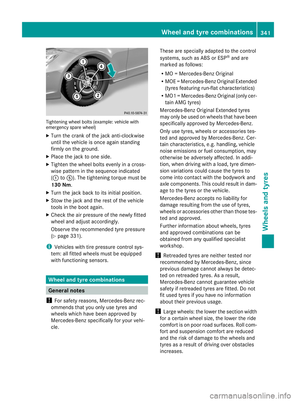
Tightenin
gwheel bolts (example: vehicle with
emergenc yspare wheel)
X Turn the crank of the jack anti-clockwise
until the vehicle is once again standing
firmly on the ground.
X Place the jack to one side.
X Tighten the wheel bolts evenly in across-
wise pattern in the sequence indicated
(: toA). The tightening torque must be
130 Nm.
X Turn the jack back to its initial position.
X Stow the jack and the rest of the vehicle
tools in the boot again.
X Check the air pressure of the newly fitted
wheel and adjust accordingly.
Observe the recommended tyre pressure
(Y page 331).
i Vehicles with tire pressure control sys-
tem: all fitted wheels must be equipped
with functioning sensors. Wheel and tyrec
ombinations General notes
! For safety reasons, Mercedes-Benz rec-
ommends that you only use tyres and
wheels which have been approved by
Mercedes-Benz specifically for your vehi-
cle. These are specially adapted to the control
systems, such as ABS or ESP
®
and are
marked as follows:
R MO =Mercedes-BenzO riginal
R MOE =Mercedes-Benz Original Extended
(tyres featuring run-flat characteristics)
R MO1 =Mercedes-BenzO riginal (only cer-
tain AMG tyres)
Mercedes-Benz Original Extended tyres
may only be usedonw heels that have been
specifically approved by Mercedes-Benz.
Only use tyres, wheels or accessories tes-
ted and approved by Mercedes-Benz. Cer-
tain characteristics, e.g. handling, vehicle
noise emissions or fuel consumption, may
otherwise be adversely affected. In addi-
tion, when driving with aload, tyre dimen-
sion variations could cause the tyres to
come into contact with the bodywork and
axle components.T his could result in dam-
age to the tyres or the vehicle.
Mercedes-Ben zaccepts no liability for
damag eresulting from the us eoftyres,
wheel soraccessorie sothe rthan those tes-
ted and approved.
Further information about wheels, tyres
and approved combinations can be
obtained from any qualified specialist
workshop.
! Retreaded tyres are neither tested nor
recommended by Mercedes-Benz, since
previous damage cannot always be detec-
ted on retreaded tyres. As aresult,
Mercedes-Ben zcannot guarante evehicle
safety if retreade dtyres are fitted. Do not
fit used tyres if you have no information
about their previous usage.
! Large wheels :the lower the section width
for acertain wheel size, the lower the ride
comfort is on poor road surfaces. Roll com-
fort and suspension comfort are reduced
and the risk of damage to the wheels and
tyres as aresult of driving over obstacles
increases. Wheel and tyrec
ombinations
341Wheels and tyres Z